
Now that the 2014 edition of the National Electrical Code® (NEC®) has been published let’s look at what’s new in the requirement for arc energy reduction in Section 240.87.
This section was added to Article 240 in the 2011 edition of the NEC. It required the use of Zone Selective Interlocking (ZSI), differential relaying, energy-reducing maintenance switching or an approved equivalent means where a circuit breaker without an instantaneous trip function is used. The motivation was to protect electrical workers better from the arc flash hazard when a short time delay is used to slow down the operation of a circuit breaker to achieve coordination in an electrical system. This section has changed significantly in the 2014 edition.
Let’s take an in-depth look at the changes and what they mean. Quotations from the NEC are shown in italics.
What’s in a name?
The title of 240.87 in the 2011 edition was Non-instantaneous Trip. In the 2014 edition, it has been changed to Arc Energy Reduction. Why the title change? The former title referred to when the requirements in the section applied while the new title refers to what the requirements in the section are intended to accomplish. Since the reason for the requirements is improved worker safety, to be accomplished by reducing the arc flash hazard, the new title makes better sense.
When do the requirements apply?
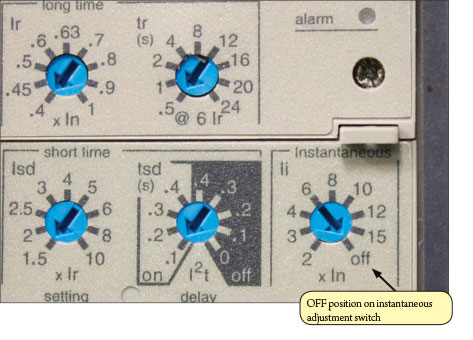
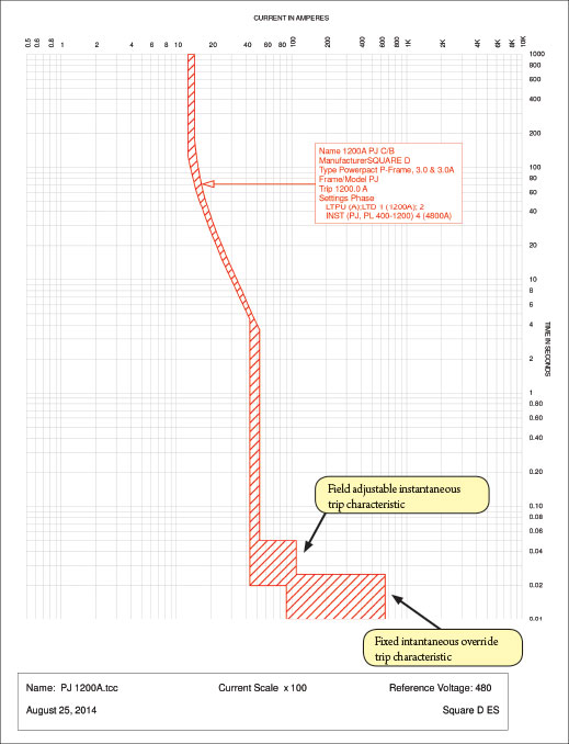
In the 2011 edition of the NEC, arc energy reduction was required whenever a circuit breaker does not have an instantaneous trip function. But what does that mean? It obviously refers to a circuit breaker with no instantaneous trip function at all. But what about a circuit breaker that has an adjustable instantaneous trip function that has been set to OFF (see figure 1)? And what about a circuit breaker that has a fixed instantaneous override (see figure 2)?
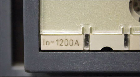
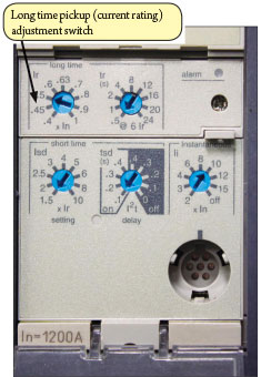
These questions were answered in the 2014 edition of the NEC which requires arc energy reduction where the highest continuous current trip setting for which the actual overcurrent device installed in a circuit breaker is rated or can be adjusted is 1200 A or higher (see figure 3). You may recognize this wording as it is similar to that used in Section 230.95 to define when ground-fault protection of equipment is required. This means that even though an electronic trip circuit breaker with a 1200 A sensor has its current rating switch set to, for example, 0.5 (600 A), it will still require an arc energy reduction means (see Figure 4).
If the overcurrent device in the circuit breaker meets this criterion, then documentation and a method to reduce the clearing time must be provided.
Methods to Reduce Clearing Time
What does clearing time have to do with arc energy reduction? To answer this question we need to understand incident energy. Incident energy, as defined in NFPA 70E, Standard for Electrical Safety in the Workplace®, is, “The amount of energy impressed on a surface, a certain distance from the source, generated during an electrical arc event. One of the units used to measure incident energy is calories per centimeter squared (cal/cm2).” A method used to calculate incident energy may be found in IEEE 1584, Guide for Performing Arc Flash Hazard Calculations.
Incident energy is a function of current and time, so if the arcing time is reduced, the incident energy will be reduced. Clearing time refers to the length of time necessary for an overcurrent protective device to extinguish the arc completely.
The 2011 edition of the NEC listed four means to reduce clearing time. The 2014 edition now lists five clearing time reduction means. They are:
(1) Zone selective interlocking
Zone selective interlocking preserves the desired coordination between main, tie and feeder protective devices and allows fast tripping for faults within the protected zone (the conductors between the interlocked devices). This is accomplished via wired connections between circuit breaker electronic trip units, ground fault relays or protective relays. If a feeder device detects an overcurrent condition it sends a restraining signal to the upstream device(s). The upstream device(s) then follows its normal time-current characteristic and serves as a backup. However, if the upstream device detects an overcurrent condition above its short time (or ground fault) pickup setting, but the downstream device(s) do not (e.g., due to a main bus fault), then the main circuit breaker will not receive a restraint signal and it will trip with no intentional time delay. In this way, ZSI offers the “best of both worlds” — fast clearing of fault currents without sacrificing coordination. Furthermore, ZSI is available on both low- and medium-voltage equipment, and can be applied for both phase faults and ground fault protection.
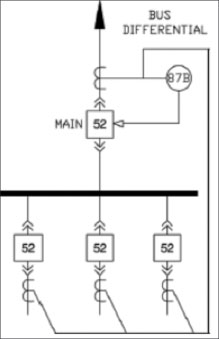
(2) Differential relaying
Differential relaying protection is another option to reduce arc energy (figure 5). The concept of this protection method is that current flowing into the protected zone must equal the current flowing out of the zone. If these two currents are not equal, a fault must exist within the zone, causing the relay to operate. Differential relaying uses current transformers located on the line and load sides of the protected equipment, a fast acting relay and a shunt trip on a circuit breaker or switch. Differential relays are very sensitive to faults inside their zone of protection but are immune to load inrushes or pass-through faults.
Differential relaying protection is often applied at medium voltage and is less common at low voltage due to the increased space requirements for relay class current transformers, differential protective relays and additional wiring complexity. The costs associated for low-voltage differential relaying protection are also substantial when compared to the cost of the base equipment. Saturation of the current transformers at high fault currents is also a concern.
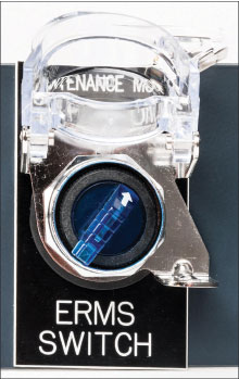
(3) Energy-reducing maintenance switching with local status indicator
An energy-reducing maintenance switch (figure 6) allows a worker to set a circuit breaker electronic trip unit or protective relay to operate faster should an arc fault occur while the worker is working within an arc-flash boundary as defined in NFPA 70E-2012. After he completes the task, the worker would then set the maintenance switch back to its normal setting. What the maintenance switch does is to reduce temporarily the pickup and/or time delay settings or to cause an alternate setting to become effective. In some cases, it may even enable a faster-acting instantaneous trip function. To be effective, the “maintenance mode” settings must result in a faster tripping time based on the actual prospective fault current levels at the location being protected.
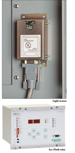
(4) Energy-reducing active arc flash mitigation system
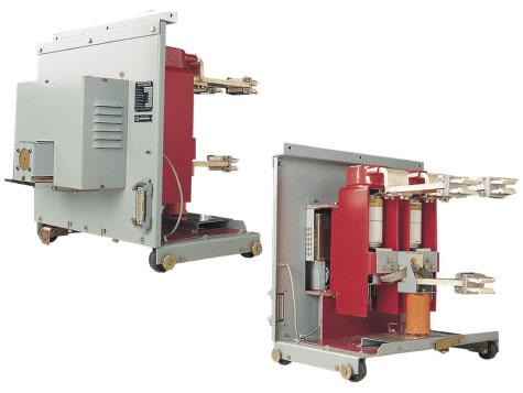
An energy-reducing active arc flash mitigation system can reduce the arcing duration by causing the upstream circuit breaker to open more rapidly, or by creating a low impedance current path. The former approach may utilize relays that sense light, current and/or other parameters (figure 7). Various means to accomplish the latter are available, the most common of which is typically referred to as a “crowbar” switch (figure 8). The closing of this switch, located within a controlled compartment, will cause the arc fault current to transfer to a new current path while an upstream circuit breaker clears the fault. The system works without compromising existing selective coordination in the electrical distribution system.
(5) An approved equivalent means
The code-making panel added this text to the Code, stating that, “ ‘Other approved means’ was added to allow for future technology” (2011 ROP 10-82). As the technology to reduce the arc flash hazard is sure to evolve, this was a wise addition to the original proposal.
Since ZSI, differential relaying and energy-reducing maintenance switches all cause a circuit breaker or switch to open instantaneously should an arc flash occur; it seems obvious that the instantaneous trip function on a circuit breaker should be considered an approved equivalent means. An instantaneous trip function, whether it is field adjustable or a nonadjustable override type, can reduce the arc energy if its pickup point is set below the prospective arc fault current.
Code Compliance vs. Improved Safety
This relatively new section in the NEC is well intended, but it is too easy to meet the letter of the requirement without meeting the spirit of the requirement, namely an improvement in worker safety, or even an actual reduction in arc energy. Just supplying one of the listed means to reduce the clearing time in the event of an arc fault may or may not improve safety. Here are a few considerations to keep in mind:
The sensing function, whatever it is, needs to be set to activate (pickup) at a point below the prospective arcing fault current.
Each one of the means listed establishes a zone of protection, in other words, the clearing time will be reduced for faults within the zone but not for those outside it. For example, the line side of a main circuit breaker would be outside the protected zone for any means provided within the equipment where the main circuit breaker is located.
The means may not reduce the level of incident energy listed on the arc flash label to be applied to the equipment per NFPA 70E and, thus, may not reduce the type of personnel protective equipment (PPE) that must be worn.
The means may not reduce the incident energy enough to allow workers to use a lower level of PPE.
Recommendations
Ideally, in order to achieve enhanced safety, the following should be considered:
- Conduct an arc flash study.
An arc flash study, involving the determination of the level of the prospective arcing fault current, should be performed such as is described in IEEE 1584.
- Effectively use energy-reducing maintenance switching and instantaneous tripping.
Make sure that the trip level of any of these means is below the prospective arcing fault current level. Conduct a coordination study to ensure that unwanted tripping will not occur due to high inrush currents that may occur when large motors are started, and transformers are energized.
- Be aware of the protected zone.
Each of the energy reduction means listed in 240.87 effectively establishes a protected zone; however, the work to be done may not be in the protected zone or may expose the worker to energized conductors outside the protected zone, such as the line side terminals on a main circuit breaker.
- Arc flash labeling.
Implementing an energy reduction means listed in 240.87 will not necessarily result in a reduction in the incident energy or PPE category that must be listed on the arc flash label on the equipment per NFPA 70E. In determining the proper labeling of equipment, all potential energized conductor exposures must be considered, not just those within the protected zone.
- Safety by design.
Consider safety by design techniques such as compartmentalization, protective barriers, insulated bus, remote mounting of main disconnects, etc.
Of course, de-energizing equipment any time a maintenance activity is conducted is without a doubt the best arc flash mitigation action that can be taken. Following the NFPA 70E guidelines to protect workers as well as having trained personnel, labeled equipment and a well-established maintenance process are essential elements of an effective and comprehensive arc flash mitigation solution.