Part 2 will cover proposed changes located in Chapters 4 through 8 of the NEC. As stated previously in Part 1, there were 4,012 public inputs (PI) submitted to the National Fire Protection Association (NFPA) recommending changes from the 2014 NEC to the 2017 NEC. From those public inputs, 1,235 First Revisions (FR) were created by the different code-making panels (CMP). Under the new NFPA Code development system, these first revisions are the proposed changes to the next edition of the NEC and are created based primarily on the acted upon PIs. There were four new articles proposed and accepted for the 2017 NEC as we detailed in Part 1.
Chapter Four – Equipment for General Use
New: 404.22 – Electronic Lighting Control Switches
A new provision was proposed requiring all electronic lighting control switches to be listed. This new provision goes on to prohibit these electronic lighting control switches from introducing current on the equipment grounding conductor during normal operation. This proposal would have a future effective date of January 1, 2020. Section 404.2(C) generally requires a grounded (neutral) conductor to be installed at switch locations that control lighting loads. When CMP-9 initiated 404.2(C) in the 2011 NEC, it was intended to begin a process that would ultimately result in no current being intentionally introduced onto the equipment grounding system as a result of the installation of electronic switching devices, such as an occupancy sensor. Currently, existing listed products, per the manufacturer’s instructions, direct the installer to utilize the “green” or bare equipment-grounding conductor to be connected to the device to act as the grounded conductor to power the electronics with 120 volts. The equipment-grounding conductor should not be used to complete this circuit under any circumstance. This proposed new section would require the insulated grounded conductor to be installed and used with the proper listed electronic device. The future effective date provides the manufacturers a reasonable time frame to produce these switching devices with grounded conductor compatibility while being able to use existing inventory.
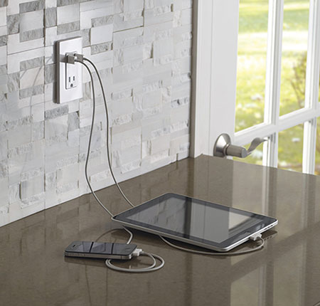
New: 406.3(F) – Receptacle with USB Charger
New provisions have been proposed for Article 406 pertaining to 125-volt 15- or 20-ampere receptacles that additionally provide Class 2 power in the form of a USB charger. These new provisions require these devices to be listed and constructed such that the Class 2 circuitry is integral with the receptacle. Currently, Article 406 contains requirements for an assortment of different types of receptacles—such as an isolated-ground type receptacle, weather-resistant and tamper-resistant type receptacles—but no provisions exist requiring a receptacle providing power to Class 2 equipment to be listed. Outlet devices consisting of a Class 2 power supply and Class 2 output connector(s) are presently readily available to the public. Some of these assemblies are intended to be secured and directly connected to a duplex receptacle. The combination of the Class 2 assembly and duplex receptacle has not been investigated to national standards. The product standard for receptacles, ANSI/UL 498, Attachment Plugs and Receptacles, corresponds to the required construction and to the performance requirements to evaluate the suitability of a receptacle with integral power supply with Class 2 output connectors. Requiring the use of a listed receptacle with an integral power supply with Class 2 output connectors will confirm that the installed device complies with the appropriate product standard.

Revision: 406.12 – Tamper-Resistant Receptacles
The requirements and locations for tamper-resistant receptacles have been proposed to be expanded. Currently, tamper-resistant receptacles are required at dwelling units, guest rooms and guest suites of hotels and motels, and in child care facilities. The proposed expansion would bring these safety devices to preschools and elementary education facilities; business offices, corridors, waiting rooms and the like in clinics, medical and dental offices and outpatient facilities; to assembly occupancies such as places of awaiting transportation, gymnasiums, skating rinks, auditoriums; and to dormitories. These expanded locations are areas that small children frequently occupy. The current exception will also be extended to these new locations. Tamper-resistant (TR) receptacles are currently limited to nonlocking-type 125-volt, 15- and 20-ampere receptacles. In the proposed new text, “125-volt” has been removed to include all non-locking 15- and 20-ampere receptacles (not just 125-volt rated). Another interesting change to the tamper-resistant receptacle requirements is a reference to 550.13, as well as to 210.52 for areas of the dwelling unit where tamper-resistant receptacles are required. This will clarify that tamper-resistant receptacles are, indeed, required in mobile and manufactured homes.
Revision: 408.3(A)(2) – Barriers at Service Panelboards, Switchboards, and Switchgear
Panelboards have been added to the type of service equipment, along with switchboards and switchgear, that will require barriers to be placed in these service enclosures to prohibit uninsulated, ungrounded service busbars or service terminals from being exposed to inadvertent contact by persons or maintenance equipment while servicing load terminations. Access to uninsulated live parts on the line side of a service disconnect within panelboards has been identified as a safety concern for several Code cycles. The proposed addition of panelboards would introduce a level of isolation from service-side uninsulated live parts for service panelboards in a manner similar to that currently afforded service switchboards and switchgear. Providing such protection is more readily achieved for those panelboards designed for a single-service disconnect, but is less practical for panelboards designed for multiple-service disconnects. With this in mind, the proposed exception would exempt this barrier provision for service panelboards with provisions for more than one service disconnect within a single enclosure as permitted by 408.36, Exceptions 1, 2, and 3. This revision is intended to complement the new construction requirement in UL 67, Panelboards, and address the safety concern of access to ungrounded, uninsulated live parts. This requirement for barrier-type panelboards has been in place for Canadian service equipment for many years. This will now allow an “electrically safe work condition,” as defined in NFPA 70E, to be established when performing electrical work in service equipment while energized.

Photo 2: Service panelboards with barriers for Canadian service equipment.
Photo courtesy of Square D/Schneider Electric.
New: 409.23 – Available Fault Current (Industrial Control Panels)
New provisions were proposed for a field marking requirement for industrial control panels indicating the available fault current. This proposed field marking would be similar to the available fault-current field marking requirements of 110.24(A). If this provision is successful, whenever an industrial control panel was marked with a short-circuit current rating in accordance with 409.110(4), the available short-circuit current at the industrial control panel and the date the short-circuit current calculation was performed would be required to be documented and made available to those authorized to inspect the installation. Typically, listed industrial control panels are being properly marked with the short-circuit current rating by the manufacturer, but there is currently no information on the job site as to the available short circuit at the industrial control panel for the authority having jurisdiction to assure that the equipment is properly sized and being properly protected.
Revision: 422.16(B)(2) – Built-In Dishwashers
A built-in dishwasher is allowed to be cord- and plug-connected. Proposed revisions would allow only the receptacle outlet for a cord- and plug-connected dishwasher to be located in the space adjacent to the dishwasher. Current provisions will allow this receptacle outlet to be placed in the same space as the dishwasher or in the space adjacent to the dishwasher. UL Product Standard 749, Household Dishwashers, was referenced as the main reason for this proposed change. UL 749 requires the receptacle outlet to be installed in a location adjacent to the dishwasher and will not allow this receptacle outlet in the same space as the dishwasher, as the present edition of the NEC allows. This product standard also calls for a receptacle outlet to be installed within 1.83 m (6 ft) of the appliance. With this in mind, it was proposed to lengthened the cord for a built-in dishwasher from 0.9 m to 1.2 m (3 ft to 4 ft) to 0.9 m to 2.0 m (3 ft to 6½ ft), measured from the face of the attachment plug to the plane of the rear of the appliance. Some will argue that this “adjacent space” requirement will often lead to the cord passing through a cabinet divider or wall and would be in conflict with requirements in 400.8 that will not allow a flexible cord to be run through walls. This one will be interesting to watch throughout the 2017 NEC development process.

Revision: 445.11 – Marking (Generators)
In addition to the nameplate information currently required for a generator, the marking and nameplate requirements for all stationary generators and portable generators rated more than 15 kW have been proposed to be revised to include not only the power factor, the subtransient, and the insulation system class but also the transient reactances, and the maximum short-circuit current. The term transient reactances was changed from “transient impedances” to provide the correct industry term. Having the generator marked with the maximum short-circuit current rating will assist the enforcement community as well as the installer when verifying proper overcurrent protection in the field. According to CMP-13, newer generators are being manufactured with inverter-based designs. Determining fault-current ratings for these generators is difficult and is best marked on the generator by the manufacturer. Stationary and portable generators will also be required to be marked to indicate if the generator is protected against overload by inherent design, an overcurrent protective relay, circuit breaker, or fuse. This information will assist the authority having jur-isdiction (AHJ) in determining compliance with 445.13 for the ampacity of the conductors.
Chapter Five – Special Occupancies
Relocation: 500.2 – Definitions: Hazardous (Classified) Locations
The existing definitions presently located at 500.2 have been proposed to be relocated to Article 100 to comply with the NEC Style Manual, which states that a definition used in two or more articles is required to be located in Article 100. Some of these definitions are already located in Article 100 and duplicated at 500.2. Other definitions that applied to two or more articles in Articles 501 through 516 were placed at 500.2 for convenience to the users of these hazardous (classified) location articles; this placement also violates the NEC Style Manual. Some in the electrical industry will argue that definitions that are only applicable to NEC Chapter 5 need to remain within the .2 sections within the articles in Chapter 5 so that the information needed for the hazardous location user is readily available, since these users typically don’t get too far outside of NEC Chapter 5. This will be another interesting change to follow during the 2017 NEC Code development process.
Revision: 501.10(B)(1) – Wiring Methods for Class I, Division 2
The wiring methods permitted for Class I, Division 2 locations have been proposed to be expanded to include rigid metal conduit (RMC) and intermediate metal conduit (IMC) with listed threadless fittings, along with the addition of electrical metallic tubing (EMT) with listed fittings. According to CMP-14, these wiring methods provide an appropriate level of safety for a Class I, Division 2 location. There seems to be little validation for currently requiring only threaded couplings and fittings for RMC and IMC in Class I, Division 2 locations since the present Code requirements permit cables with threadless fittings to be installed in Class I, Division 2 locations. EMT was added as this wiring method offers greater physical protection than some of the wiring methods currently allowed at 501.10(B)(1). Sealing with threaded connections at the Class I, Division 2 boundaries is already addressed at 501.15(B)(2). Cablebus was also proposed to be added as it provides a level of safety equivalent to the other wiring methods permitted for Class I, Division 2 locations. According to the substantiation, cablebus is similar to installed cable tray with spacing on the conductors. Cable tray is already allowed in a Class I, Division 2 location, so cablebus with insulated cables should be an allowed wiring method as well.

New: Tables 511.3(C) and 511.3(D) – Tables for Major and Minor Repair Garages
Two new tables have been proposed to be added at 511.3. These tables contain detailed information on the extent of the classified locations for major and minor repair garages with heavier-than-air fuel and the extent of classified locations for major repair garages with lighter-than-air fuel, respectively. In order to align with NFPA 30A, Code for Motor Fuel Dispensing Facilities and Repair Garages, 511.3(C) and 511.3(D) are proposed to be replaced respectively in their entirety with a new 511.3(C) covering both major and minor repair garages where heavier than air gaseous Class I liquids are transferred or dispensed, and a new 511.3(D) covering major repair garages where vehicles using lighter than air gaseous fuels are repaired or stored. These new tables are replicas of the corresponding portions of Table 8.3.2 of NFPA 30A. These tables are similar in structure to the tables in Article 514 and should provide the same “user-friendly” format as their Article 514 counterparts.

Revisions: 517.2 – Definitions: Health Care Facilities
Several definitions for health care facilities were proposed to be updated to match recent changes to definitions in NPFA 99, Health Care Facilities Code, and to update extracted material references. One of the more interesting revised definitions was to the term, Health Care Facilities. This term now will include buildings, portions of buildings, or “mobile enclosures” in which human medical, dental, psychiatric, nursing, obstetrical, or surgical care are provided. Previously, it was difficult to include a mobile recreational vehicle (RV) or a mobile home being used on a temporary basis as a medical health care facility because “mobile enclosures” were not in the definition of a health care facility. For the 2015 edition of NFPA 99, the list of examples of occupancies that may qualify as a health care facility was removed, resulting in the same change in NEC Article 517. A new informational note has been proposed to follow the definition of “Health Care Facilities” as this list is valuable to installers and inspectors in identifying certain types of occupancies that may qualify and require compliance with Article 517.
Revision: 517.31(B) – Essential Electrical Systems Transfer Switches
Revisions to 517.31(B) [previously 517.30(B)(2)] have proposed that the transfer equipment for all three branches of the essential electrical system of a health care facility meet the emergency system requirements in 700.5(A), (B), and (C) where commercially available. Current Code text requires only the transfer equipment for the life safety branch to meet requirements of Article 700 for emergency systems (see 517.26). Transfer switch malfunctions are a huge concern when essential electrical systems fail. Assuring that all transfer switches of all of the branches of the essential electrical system meet the same requirements as emergency systems found in other types of occupancies will help the health care facility’s essential electrical system protect patients and health care personnel during times of emergencies and/or disasters.

Chapter Six – Special Equipment
New: 600.34 – Photovoltaic (PV) Powered Signs
A new section and a new definition have been proposed to be added to Article 600 to cover signs that are powered by a solar photovoltaic (PV) system. These types of signs are defined as a complete sign powered by solar energy consisting of all components and subassemblies for installation either as an off-grid stand-alone, on-grid interactive or non-grid interactive system. The installation rules for the PV system are found in Article 690. Signs are a special application of PV equipment requiring special installation instructions. These PV-powered signs are described and covered by UL Standard 48, Electric Signs, Section 4.4.4.12. This new section of NEC Article 600 will provide rules for field wiring and the installation and safe usage of PV-powered signs. This section is also intended to harmonize Article 600 with Article 690 and the end use of PV signs constructed per UL 48.

Deletion: Table 680.10 – Minimum Cover Depths – Swimming Pools
Do the requirements for underground wiring related to swimming pools located in 680.10 apply outside the 1.5 m (5 ft) radius of a swimming pool? These and other questions have been proposed to be answered as Section 680.10 (now proposed to be 680.11) has been revised to clarify which underground wiring can or cannot be installed under and around swimming pools. This also clarifies that the wiring methods underground near swimming pools must be installed in a manner to withstand the conditions unique to the pool environment, and that only wiring related to swimming pools may be run under the pool to feed such things as underwater wet-niche luminaires, etc. The revised text resolves some possibly conflicting language stating that only swimming pool-related wiring may be installed underground within 1.5 m (5 ft); and then in the next sentence, 680.10 permits other wiring within the 1.5 m (5 ft) zone limited to pool-related wiring. CMP-17 determined that all underground wiring should be installed per the burial depths of Table 300.5, thus eliminating the requirement for Table 680.10.
New: Article 680 Part VIII – Electrically Powered Pool Lifts
A new Part VIII and a new definition have been proposed to address an ever growing concern for safety involving electrically powered pool lifts being installed all across the country around swimming pools, spas, and hot tubs. The proposed definition is: Electrically powered pool lifts are an electrically powered lift that provides accessibility to and from a pool or spa for people having disabilities. Installation of these pool lifts has been occurring, and continues to occur, all across the country for compliance with Department of Justice and Building Code requirements. These lifts allow persons with disabilities to have access to public pools, spas, and hot tubs. This equipment is currently being installed without compliance to current NEC requirements, such as equipotential bonding. This proposed new part to Article 680 attempts to permit a compliant installation with adequate safety requirements for all swimming pool users, and would cover such things as listing and labeling requirements, GFCI protection for personnel, bonding requirements, switching devices, and nameplate information and requirements.

Revision: 690.8(A)(1) – Calculation of Maximum PV Source Circuit Current
Proposed revisions to the calculation methods for photovoltaic (PV) systems would allow engineering supervision to be used in calculating maximum source circuit current for PV systems with a generating capacity of 100 kilowatts or greater. Current provisions only allow this current to be calculated by the sum of parallel PV module rated short-circuit currents multiplied by 125 percent. The substantiation of this revision points out that an engineer qualified to design PV systems is capable of making the necessary calculations or running the necessary simulations to develop accurate maximum circuit currents of PV source circuits based on the specifics of an installation location. While the use of short-circuit current method as the maximum current is still allowed, recent improvements in ground-fault protection could make the use of short-circuit current as the maximum current an obsolete concept. The new proposed text allowing the calculated maximum current value using the engineering supervision method is not permitted to be less than 70 percent of the value calculated using rated short-circuit currents methods.
New: 695.15 – Surge Protection for Fire Pumps
A new provision was proposed for fire pumps that would require a listed surge protection device to be installed in or on the fire pump controller. A surge protection device (SPD) is necessary to provide protection for the fire pump controller. According to the substantiation for this new SPD requirement, a study titled, “Data Assessment for Electrical Surge Protective Devices” commissioned by the NFPA Fire Protection Research Foundation, showed that 12% of the fire pumps tested had damage due to voltage surges. Much of this damage could have been prevented with properly sized surge protective devices. With fire pumps being so critical for life-safety, SPDs are a small price to pay to ensure these precarious devices remain in good working condition.
Chapter Seven – Special Conditions
New: 700.3(F) – Temporary Source of Power for Maintenance or Repair of the Alternate Source of Power for Emergency Systems
New prescriptive language was proposed to be added to 700.3 detailing requirements, along with an exception, that recognizes whether a permanent switching means to connect temporarily an alternate source of power (such as a generator) is or is not required. If the emergency system relies on a single alternate source of power and this system must be disabled for maintenance or repair, the emergency system must include permanent switching means to connect a temporary alternate source of power for the duration of the maintenance or repair. The existing last paragraph in 700.4(B) provides a performance-based requirement for a portable or temporary alternate source to be available whenever the emergency generator is out of service for “major” maintenance or repair. The term major is very subjective, and no prescriptive requirements currently exist for this situation. Minor maintenance such as an oil change would not be considered major maintenance but could disable a generator source for several hours.
New: 700.25 – Branch Circuit Emergency Lighting Transfer Switch
A new section was proposed to be added to Article 700. This would permit emergency lighting loads supplied by branch circuits, rated at not greater than 20 amperes, to be transferred from the normal branch circuit to an emergency branch circuit using a listed branch-circuit emergency-lighting transfer switch. This provision goes on to clarify that the mechanically held requirements of 700.5(C) are not to apply to listed branch-circuit emergency-lighting transfer switches. This addition is intended to accommodate a new class of transfer switching devices intended for operation of individual branch circuits in an emergency lighting system.
During the 2011 Code cycle, 700.24 (now 700.25) was added to the NEC. This section covers the requirements for automatic load control relays (ALCR). The section specifically states: “The load control relay shall not be used as transfer equipment.” These devices are evaluated in accordance with UL 924, Standard for Emergency Lighting and Power Equipment. These ALCRs were never intended for use as general-purpose transfer equipment, even though these devices fall within the NEC definition of transfer equipment.
Currently, listed ACLRs with transfer features are being installed in the field in violation of current NEC 700.25. Most of these devices have undergone no evaluation as emergency transfer switches. These devices, along with transfer-capable ALCRs, are now being listed and evaluated under UL Product Standard 1008, Transfer Switch Equipment as “Branch Circuit Emergency Lighting Transfer Switches” (BCELTS).
BCELTS devices will now be evaluated for comparable performance and construction requirements as those applied to traditional emergency-transfer switches when used on branch circuits rated up to 20 amperes.
Revision: 770.24 – Mechanical Execution of Work: Optical Fiber Cables
Revisions to 770.24 were proposed to require protection against physical damage to optical fiber cables in accordance to all of 300.4—not just 300.4(D) through (G) as is currently required. The text was also revised to reference 300.4 in its entirety as optical fiber cables need to be protected from all sources of damage. This revision is necessary with the ever expanding use of optical fiber cables in critical circuits such as fire alarm, and not just in communications circuits. Physical protection requirements will now apply to areas such as bored holes structural joints in conjunction with optical fiber cables. The last sentence of 770.24 was also revised by adding “in accordance with 800.170(C).”
The NEC reader/user should be alerted to the additional listing information for nonmetallic cable ties for use in other space used for environmental air (plenums) contained in 800.170(C). Some of these same revisions were proposed for 800.24, 820.24, and 830.24.

Chapter Eight – Communication Systems
Revision: 840.48 – Unlisted Wires and Cables Entering Buildings for Premises-Powered Broadband Communications Systems
In order to expand the coverage of Article 840, there is a proposal to recognize both twisted pair and coaxial cable-based systems in addition to optical fiber-based systems. In addition to the current reference to 770.48 for installations of unlisted optical fiber cables entering buildings, new references have been added for 800.48 unlisted communications wires and unlisted multi-paired communications cables entering buildings, and 820.48 for unlisted coaxial cables entering buildings.
The term optical network terminal (ONT) at 840.2 was revised to network terminal, and the definition was revised to accommodate twisted pair-based and coaxial cable-based systems in addition to optical fiber-based systems.
Informative Annex D – Examples
Revision/New: Example D7 – Sizing of Service Conductors for Dwelling(s)
The example for sizing of service conductor for dwelling units at Example D7 was proposed to be revised to clarify the use of correction and adjustment factors. The example would now include provisions for sizing dwelling unit service conductors with no required adjustment or correction factors, and provisions with required temperature correction factors such as ambient temperature correction factors at Table 310.15(B)(2)(a). The previous table information that was located in Table 310.15(B)(7) prior to the 2014 NEC was re-inserted at Example D7. This table was added to show the dwelling-unit service conductor sizes required if there were no adjustment or correction factors to be applied.
This article is an effort to provide readers with current information about proposed revisions that have been approved thus far in the 2017 NEC Code development process. Part 1 of these revisions covering key proposed changes located in NEC Chapters 1 through 3 was published in the May-June 2015 issue of IAEI magazine. These proposed changes are not set in stone as we are still in the middle of the 2017 NEC development process and are subject to changes based on Public Comments, etc. The final version of the 2017 NEC is scheduled be published in September 2016. These changes and many others will be featured in IAEI’s Analysis of Changes, 2017 NEC scheduled to be published during the same time frame as the 2017 NEC.