For an owner, planning a larger commercial-scale solar photovoltaic (PV) installation involves a myriad of decisions about size, equipment, design, location, and perhaps most important, the installation contractor. With all these concerns to address, it’s not easy to fully understand how a proposed installation will turn out. Even if an authority having jurisdiction (AHJ) is comfortable with inspecting residential PV systems for code-compliance, the process may seem overwhelming for larger commercial systems. However, the process can be manageable with a clear understanding of National Electrical Code (NEC) requirements and early communication to help establish that these requirements are understood.
A structured process typically starts at the design and permitting stage and involves a plan review to ensure that the proposed installation will comply with the local codes, standards, and any other requirements. The next two important steps, the pre-construction meeting, and interim inspections, though widely understood and simple to achieve, are often overlooked. Without these important steps, projects often incur thousands of dollars of unnecessary expenses and hundreds of hours of delays.
The pre-construction meeting
A pre-construction meeting often consists of the AHJ, design engineer, electrical contractor, and other quality assurance inspectors such as the owner’s agent or independent engineer. This is usually the only occasion where all parties are together in one location to discuss the project. During this meeting, the different stakeholders can exchange contact information, address questions or concerns with the design, discuss local standards and common violations, and establish project milestones.
Interim or “rough” inspections
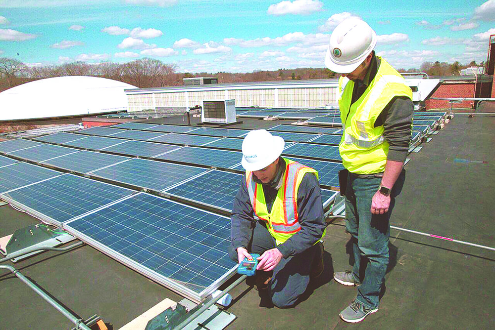
Project milestones are when very brief interim or “rough” inspections are necessary to ensure the installation is compliant with the approved design and code requirements as the work is underway. The concept of a rough inspection and a final inspection is very familiar to many contractors and AHJs. During the interim inspection, the AHJ can review equipment working spaces and properly examine the installation prior to any concealment. For a solar PV installation, the AHJ can check the racking, grounding, and wiring methods prior to the installation of the modules.
Should this be the very first time the AHJ visits the site?
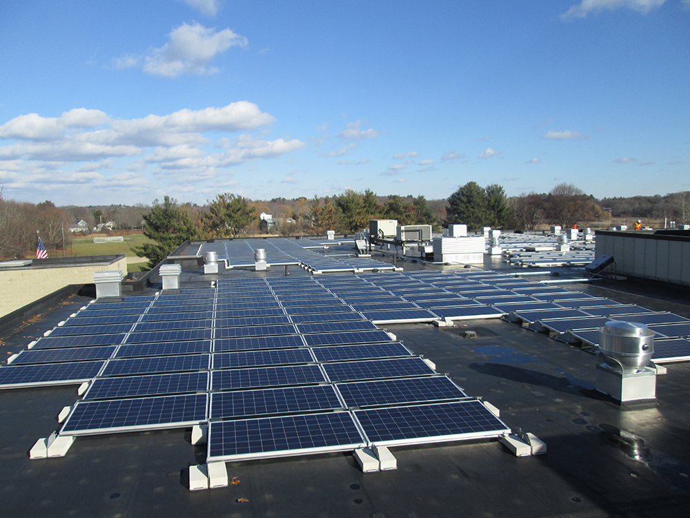
A typical larger solar PV installation consists of standard components and installation methods, repeated hundreds or thousands of times across the array location, whether on a roof, in a field, or another area. An important project milestone is to inspect the method for array installation at the beginning of construction before it is employed across the entire installation. The results from each milestone inspection should be documented to provide a reference point, should questions arise later in the installation.
The first inspection milestone
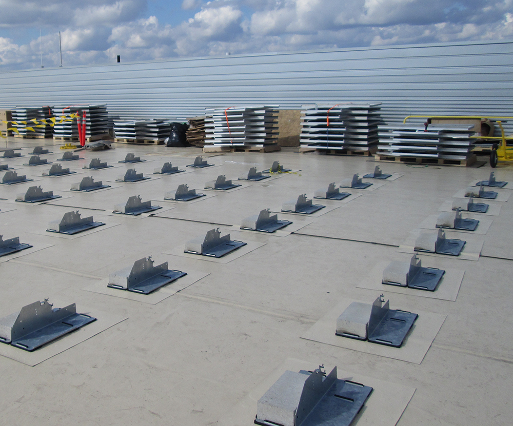
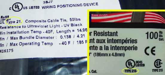
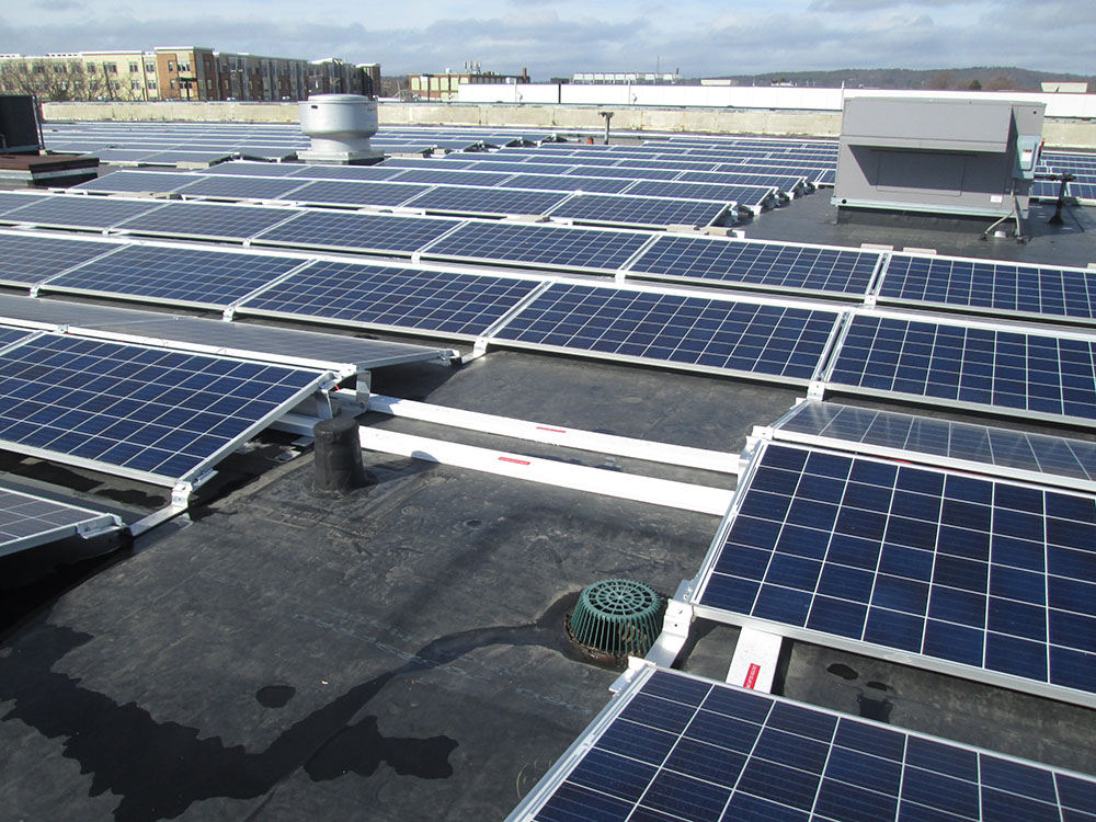
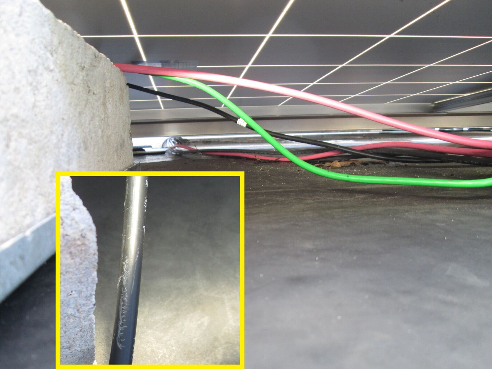
The first milestone inspection is typically at the beginning of module installation so the AHJ has a clear understanding of how the PV conductors will be supported and protected and if their installation complies with code. The contractor should provide accurate component specification sheets to ensure proper compliance. Conductors that are not properly supported and secured can be easily damaged by abrasive parts of the racking, ballast blocks (cement pavers used to weight the array to the roof (see photo 2), or exposure outside of the module area. The AHJ should also consider environmental conditions, such as UV exposure, wet location, and temperature variation, of the components to be installed.
Arrays in readily accessible locations must comply with Article 690.31(A), requiring additional guarding or protective wiring methods. In the 2014 NEC, Article 300.4 simply states “where subject to physical damage, conductors, raceways, and cables shall be protected.” Articles 338.10(B)(4)(b) and 334.30 provide requirements on how these conductors should be secured and supported. There is a specific reference to these articles in Article 690.31(C)(1) in the 2017 NEC. Larger PV systems usually accomplish “Guarding” as defined in the NEC by being enclosed in a fenced area accessible only to “Qualified Persons.”
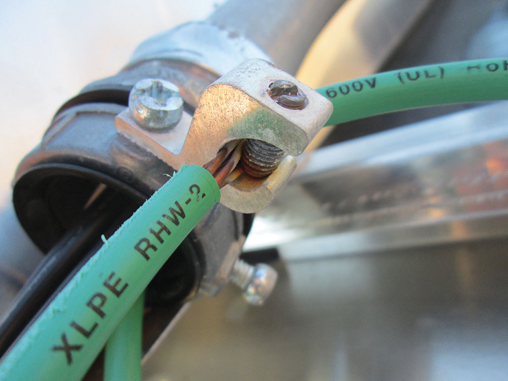
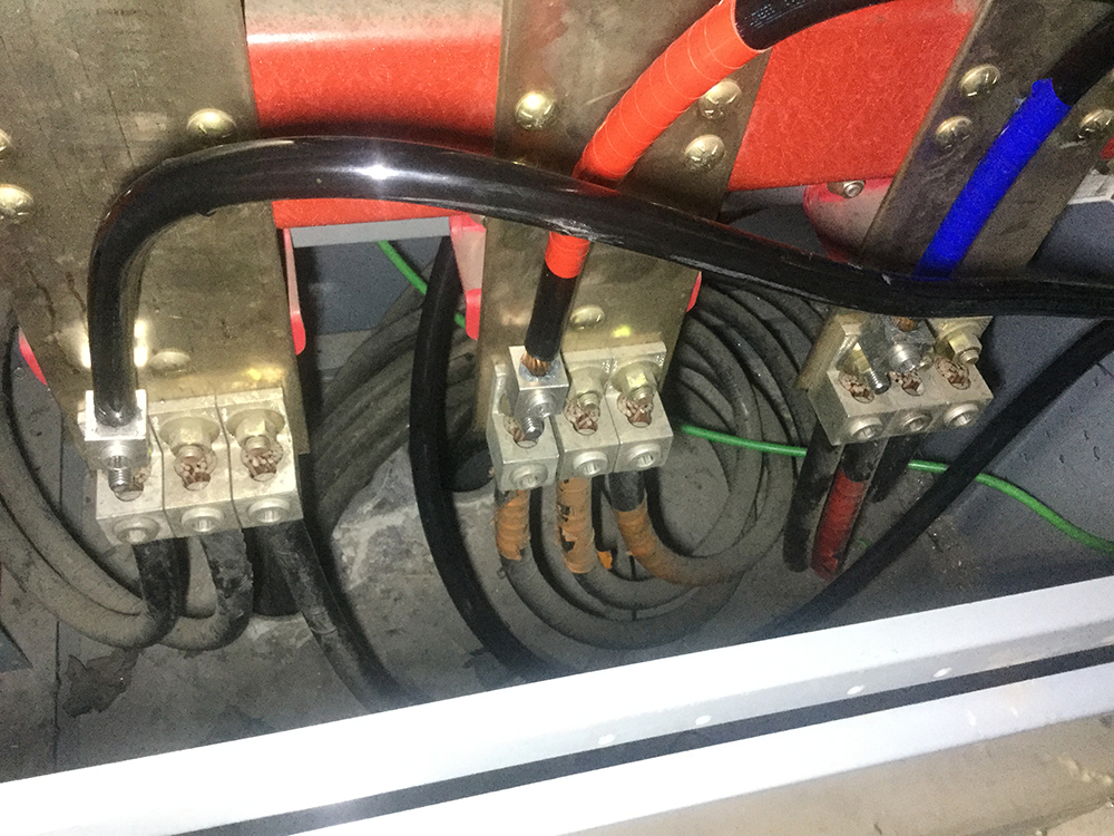
The AHJ also verifies that the module frames and racking components will be grounded according to the approved design and that these components are either identified by the manufacturer and/or suitable for the environment. Many common grounding components used by electricians are not suitable for outdoor use. Ground lugs and bonding bushings are among the most common components that are improperly used. A mounting system with a bonding and grounding system certified to UL2703, Standard for Mounting Systems, Mounting Devices, Clamping/Retention Devices, and Ground Lugs for Use with Flat-Plate Photovoltaic Modules and Panels, will provide details on the proper bonding and grounding techniques to be used.
In both the 2014 and 2017 NEC, Section 300.6 requires these components, “be of materials suitable for the environment in which they are to be installed.” In addition, Section 110.3(B) requires that “listed or labeled equipment shall be installed and used in accordance with any instructions included in the listing or labeling.” Products listed to the bonding and grounding requirements of UL2703 meet the requirements for outdoor exposure. The AHJ also needs to understand how the equipment grounding conductor will be installed in the array and give consideration to UV exposure as well as dissimilar metals if a bare copper conductor is to be used.
If additional components such as microinverters or dc-to-dc converters (dc optimizers) are part of the system, this milestone may be the only opportunity to inspect their installation prior to installation of the modules. Like the module installation, the contractor should demonstrate that the mounting and grounding methods conform to the installation instructions at the commencement of their installation. Most UL2703 bonding systems require that the PV modules be mounted before the modules and the mounting structure are fully bonded together. In addition, these products have recommended torque values as part of the mounting installation instructions especially when utilizing the attachment for bonding and grounding purposes.
Once the AHJ approves the proposed methods, the installers can use them throughout the entire array, hundreds or thousands of times.
The next inspection milestones
The AHJ must also inspect raceways and conductors that will leave the array area. Typical flat rooftops may contain many other components such as HVAC equipment that will require access for routine maintenance. The PV array layout should accommodate how conductors or raceways can be installed to minimize rooftop trip hazards across these access pathways. Depending on the progress of the installation of components outside the array area the AHJ’s inspection may help guide the best and most practical equipment location. A common field installation error is not providing adequate working space around equipment in accordance with Section 110.26.
If the system is utility-interactive as most are, it will also be important to review the interconnection plan and to understand if the proposed design will meet utility requirements. While this step is the responsibility system engineer, at times these considerations have not been properly identified. Depending on project timing, this process may occur during a prior milestone, or be independent. There are several types and location options for ac connections, and Article 705 in the NEC outlines these requirements. Some connection options permitted in 705.12(B) may make it difficult to comply with utility requirements for access to PV system disconnects. Occasionally there must be changes to the proposed design to meet these utility requirements. In general, the two primary considerations for ac connections are: first, the location of the PV system disconnect relative to the service disconnecting means and utility meter; and second, the method in which this connection will be made.
Putting the plan to action, or not …
Our firm recently completed our work as an owner’s agent to a municipality that had PV installations placed on six of their public buildings. We were fortunate to be involved during the design review phase, so we could work with the engineering firm, not only to review code and installation instruction compliance, but also to recommend specific details in the documentation that helped to reduce the assumptions made on the site. Once we finalized the review, we participated in the construction meeting with the engineers, the two electrical contractors, and the building and electrical inspector. Together we discussed remaining questions about the designs, confirmed installation schedules, logistics, inspection milestones, and exchanged information. The project manager was also identified to establish the person to coordinate project communication.
As installations proceeded on several of the buildings, we accompanied the electrical inspector on the interim inspections. The first inspection for each site took approximately 30 minutes, but subsequent visits were typically as brief as 10 to 15 minutes. The owner’s agents became very familiar with the installation and were able to facilitate needed changes early enough in construction to keep rework to a minimum. At the final inspection for each installation, there were no surprises and each one passed without corrections.
Unfortunately, the end of this story is not as good as the start. One very cold Tuesday morning, we received a call for a final inspection at the sixth building. Unbeknownst to us, a third contractor had been brought on and performed the installation. Because this contractor was given the latest set of detailed drawings—that we had reviewed and approved—this should be a smooth inspection. We knew this would be a good test to determine if the construction meeting and interim inspections had been beneficial. As we and the local AHJ walked toward the rooftop, the new contractor said that this was one of the firm’s first installations but that it had gone smoothly and the crew was proud of their accomplishment. As we have had to do several times before on other projects, we were the bearer of the bad news just minutes into our inspection.
As we began to inspect the first array location, we immediately noticed that the contractor had made no consideration for conductor support, protection, or proper wire management. Further, into the inspection, we found that all exposed bonding bushings were not suitable for the environment and were already showing signs of corrosion. We also discovered it was difficult to navigate across the roof because of several unnecessary trip hazards across pathways, and in some locations, the array completely surrounded rooftop equipment that required access.
By the end of a five-hour inspection, we observed 15 unique violations across more than 100 different locations. Weeks later, hundreds of man-hours and thousands of dollars had been spent on remediation before the system could pass the final inspection. Each violation could have been avoided at the expense of only a few hours for communication and an interim inspection or two.
Commercial PV system installations include many decisions that a contractor faces when executing an installation. Many of these decisions are not called out specifically in the plans since they involve being well-versed in code-compliant PV installation practices. The level of experience can vary considerably from company to company and even crew to crew. It is important to set expectations early in the installation and communicate key concerns well before the physical installation is completed so that minor changes can be easily incorporated. Changes that are minor during construction can avoid major problems that often result from a series of minor mistakes.
Although AHJs may have different approaches to the inspection process, establishing code supported requirements at the beginning of construction is an effective way to reduce or eliminate costly delays. A long list of corrections is painful for all parties involved in the construction. Avoiding these corrections with effective communication improves the whole installation and may even help protect the reputation of the installing contractor.
References
UL2703, Standard for Mounting Systems, Mounting Devices, Clamping/Retention Devices, and Ground Lugs for Use with Flat-Plate Photovoltaic Modules and Panels.