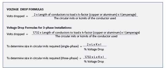
Voltage drop is only mentioned in some sections of the NEC as informational notes, and is required to be calculated in other sections of the Code. These sections are 210.19(A) Informational Note 4, 215.2(A)(1) Informational Notes 2 and 3, 310.15(A)(1) Informational Note 1, 647.4(D), 310.60(B) Informational Note 2, 455.6(A) Informational Note, and 695.7. Permitted or required amounts of voltage drop may range from 1.5 to 15 percent of the feeder or branch-circuit voltage. Five percent maximum is generally suggested on a circuit. Informational notes are not mandatory Code requirements, but are explanatory material intended for informational purposes only [see 90.5(C)].
However, manufacturers’ installation instructions, which are required to be followed in 110.3(B), often require a minimum voltage rating to be maintained in order for a particular type of utilization equipment to function properly in the manner intended by the manufacturer, and to be listed by an electrical equipment nationally recognized testing laboratory. To perform voltage drop calculations, it is essential to have the following information: 1) the k-factor, 2) the length of the feeder or branch circuit to the load, 3) the amperage load of the circuit, and, of course, 4) the circuit voltage. The k-factor is a multiplier representing the DC resistance for a given size conductor 1,000 feet long and operating at 75°C. From this information, the Code user can find either the minimum size conductor needed to carry the load (measured in circular mils or kcmil), and/or the percentage of voltage drop.

The formulas included here are based on conductor DC resistance values provided in Chapter 9 Table 8 of the NEC, and are viewed as generally acceptable for voltage drop calculations. Table 8 is based on 75°C/167°F, and provides a k-factor constant of 12.9 for copper, and 21.2 for aluminum conductors.
For example, to find the k-factor, you multiply the resistance of the conductor per foot by the circular mil of the conductor. Remember that Table 8 states resistance in ohms per 1,000 feet. For voltage drop calculations when copper wire is used, be sure to select the value from the “uncoated copper” column, as most copper conductors are uncoated. To be “coated” means that there is a tin or other type of coating on the copper conductor, which changes its resistance value. If a conductor is “coated,” then use the “coated” column resistance value. Remember that “coated” does not refer to the conductor installation. Note the following examples.
Copper wire
For Copper Wire, use the DC resistance measured in ohms from Chapter 9, Table 8:
The DC resistance of a 1,000 kcmil copper conductor is 0.0129 ohms per 1,000 feet.
(0.0129 ohms per 1,000 feet divided by 1,000 = .0000129 ohms per foot)
0.0000129 ohms per foot x 1,000,000 circular mils = 12.9 k-factor — for copper wire
Aluminum wire
For Aluminum Wire, the DC resistance measured in ohms per 1,000 feet of conductor from Chapter 9, Table 8:
(0.0212 ohms per 1,000 feet divided by 1,000 = .0000212 ohms per foot)
0.0000212 ohms per foot x 1,000,000 circular mils = 21.2 k-factor — for aluminum wire
Note: It is important to note that to find the k-factor, you multiply the resistance of the conductor per foot by the circular mil sizes of the conductor. For any copper or aluminum conductor found in Chapter 9, Table 8, the k-factor will roughly be 12.9 or very close to it for copper, and 21.2 or very close to it for aluminum. Therefore, these two amounts are chosen as k-factor constant values for uncoated copper or aluminum conductors operating at 75C/167F ambient temperatures and rated amperage.
75C/167F temperature rating is often used in today’s electrical circuits, as most new lugs in electrical distribution equipment and utilization equipment are rated 75C/167F; and 90C/194F rated conductors are used at the 75C ampacity because of the termination requirements found in 110.14(C).
The formula used is also generally acceptable for 60C/140F conductor installations.
Voltage drop is calculated for single-phase installations with the understanding that the current will be returning from the load either from a line-to-line or line-to-neutral load; therefore, the multiplier 2 is added into the formula for the resistance of the conductor to the load and back. This is necessary to complete the circuit, and to clear a fault, keeping 250.122(B) in mind, which will be discussed later.
The formula for three-phase installations uses 1.732 instead of 2 as the multiplier. Current flows out to the load and back on the phase conductors.
Once the volts dropped have been determined, use the formula below to determine the percent of voltage drop for the circuit or system.
Example 1: 7.2 volts dropped / 240 volts (1 phase) = 3% voltage drop
Example 2: 24 volts dropped / 480 volts L-L = 5% voltage drop
Choose a formula based on the conductor size used, or the maximum amount of voltage drop acceptable to the AHJ. (3%, 5%, etc.)
These formulas may be used to determine the maximum length of a conductor, the circular mil size needed for a conductor, or the voltage drop in a system or circuit.
Voltage-Drop Formulas
Legend
VD = actual volts dropped (not percentage)
K = assumed specific resistance
L = length of run to load
I = load in amps
CM = area of wire, circular mils
Note: For 3-phase formulas, replace the multiplier 2 with 1.732.
Where
2 x K x I x L / CM = VD
2 x K x I x L / VD = CM
(CM x VD) / (2 x K x I) = maximum length
(CM x VD) / (2 x K x L) = maximum I (amps)
Note: Chapter 9 Table 8 DC resistance values for k-factor and voltage drop on AC circuits are used for simplicity and consistency. Resistance values for a given size wire in Chapter 9 Table 8 are very close to the values given in Chapter 9 Table 9, regardless of which wiring method is used.
Ampere Feet
To determine ampere feet, measure the actual distance to the load and multiply that distance by the load in amperes.
Voltage Drop Examples
Example 1
A 440-volt supply circuit, single-phase 2-wire, is to be installed in magnetic steel conduit. Power factor is 80%, length of run
620 feet (310 feet x 2 = to the load and back), amperage 180, permissible voltage drop is 3%. What size Type RHW aluminum cable should be used?
Volts drop = .03 X 440 = 13.2
Ampere feet = 620 X 180 =111,600
A size 500 kcmil will give a voltage drop of:
Amp. Feet Volt drop
100,000 12.0
10,000 1.2
1,000 0.1
600 0.1
Total 111,600 13.4 Total voltage drop
A size 600 kcmil will give a voltage drop of:
Amp. Feet Volt drop
100,000 11.0
10,000 1.1
1,000 0.1
600 0.1
Total 111,600 12.3 Total voltage drop
Since the Code permits a size 600 kcmil to carry 340 amps in aluminum Type RHW, it can be used for the job in question.
NOTE THAT LENGTH OF RUN REFERS TO THE LENGTH OF THE PHYSICAL CIRCUIT – NOT THE FOOTAGE OF CONDUCTOR
(310 feet x 2 = to the load and back).
Example 1
Using a supply circuit under conditions similar to that shown in example 1, but installed in nonmagnetic conduit, what size aluminum Type RHW is required?
Volts drop = .03 X 440 = 13.2
Ampere feet = 620 X 180 =111,600
A size 500 kcmil will give a voltage drop of:
Amp. Feet Volt drop
100,000 10.6
10,000 1.1
1,000 0.1
600 0.1
Total 111,600 11.9 Total voltage drop
A size 400 kcmil will give a voltage drop of:
Amp. Feet Volt drop
100,000 12.4
10,000 1.2
1,000 0.1
600 0.1
Total 111,600 13.8 Total voltage drop
In this particular instance, 500 kcmil can be used since this size aluminum Type RHW has a current-carrying capacity of 310 amperes.
This example shows that when voltage drop is of prime importance, non-magnetic conduit will allow the use of smaller conductors.
Excerpted from IAEI’s Ferm’s Formulas and Calculations Book, 2014.


Find Us on Socials