
Commercial and institutional lighting requirements are dispersed across the NEC: Article 100 (definitions), 110 (general requirements), 210 (where lighting is required/controlled), 220 (how lighting is calculated), 404/406 (switches and wiring devices), 410 (luminaires), and 700/701 (emergency/standby). In addition, these requirements can also be found in a long list of special occupancies & equipment: 500–516 (hazardous), 517 (health care), 518 (assembly), 520–540 (theaters/studios/projection), 525 (fairs), 545–547 (manufactured/ag), 550–555 (mobile/RV/marinas), 600 (signs), 620 (elevators), 645 (IT rooms), 680–682 (water). Emergency systems live in 700/701.
Article 100 — Definitions (why they matter so much to lighting)
Article 100, Definitions, serves as the vocabulary of the Code. It defines what qualifies as a luminaire, a lighting outlet, and the environmental conditions a device must be listed for (such as dry, damp, or wet locations). It also includes the modern emergency-lighting terminology (like “Emergency Luminaire,” “Directly Controlled,” and “Emergency Lighting Control Device (ELCD)” that connects field practices to UL 924-listed products—critical when normal fixtures do double duty for egress. Keep damp/wet straight for exteriors and food service. If your drawings and submittals don’t use these terms exactly, you may face avoidable plan-review comments later. In the 2023 edition, the NEC consolidated all definitions into Article 100—no longer scattered across multiple “.2” sections—making Article 100 your primary reference for lighting terms.
Core lighting terms you actually use
- “Luminaire” / “Lighting outlet.” The Code’s basic building blocks for lighting layout, control, and load calculations. These terms drive where branch-circuit controls are required [210.70, Lighting Outlets Required], how you classify outlets, and how you count VA. [Use Article 100 for the terms, then apply 210/220/410 accordingly.]
- “Location, Damp / Wet.” These definitions determine whether a luminaire must be “damp-location” or “wet-location” rated—e.g., under canopies, roofed porches (damp), or fully weather-exposed/washdown areas (wet). Getting the location wrong is the #1 reason luminaires fail inspection in exterior and food-service spaces.
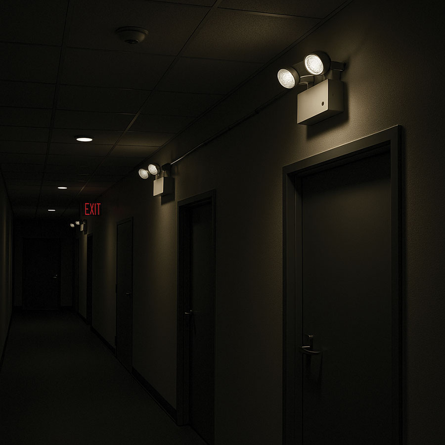
- Emergency-lighting terms. The 2023 NEC clarified the vocabulary used with Article 700 and UL 924 devices—e.g., Emergency Luminaire, Directly Controlled (a normal/emergency luminaire that’s “forced on” to emergency levels by a listed control input) and ELCD/ALCR/BCELTS devices that legally bypass or control functions during a loss of normal power. These definitions resolve longstanding ambiguity about how “normal” luminaires can serve egress when paired with listed control devices.
- Battery-equipped emergency luminaires & unit equipment. Article 100 now differentiates integral battery luminaires (which operate during both normal and emergency modes, depending on the product) from unit equipment (which operate only when the normal power fails). This distinction is important for branch circuiting, testing provisions, and the sequences of operation that you present to the AHJ.
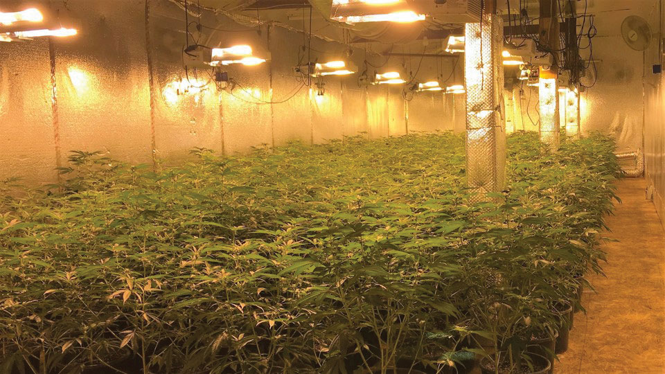
- Special-Purpose GFCI (SPGFCI). Added in 2023 to address situations where standard Class A GFCI is insufficient—particularly for higher-voltage horticultural lighting and specific pool or water-feature circuits that exceed 150 V to ground. If your specifications specify “GFCI” generally for these systems, Article 100’s SPGFCI definition (and the related article text) explains what is actually necessary.
2023 definition housekeeping that affects lighting work
- All definitions moved to Article 100. If you used to cite a definition from “410.2” or similar, update your notes—everything lives in Article 100 now, with article tags in parentheses for terms unique to a single article.
- Emergency-lighting terms standardized. Article 100 additions align with UL 924 practice and Article 700’s control topologies—critical if you’re using networked/PoE/0-10 V/DMX controls to realize emergency levels.
Field takeaway: Include the exact Article 100 term on your drawings (e.g., “ELCD, UL 924 listed,” “luminaire listed for wet location”). It prevents substitution games and speeds up approvals.
Article 110 — The pass/fail backbone
Article 110, General Requirements for Electrical Installations, does not specify lighting design; instead, it governs how lighting equipment is chosen, installed, connected, marked, protected, and maintained. Failures in a lighting system are frequently caused by issues related to Article 110.
Section 110.3(B), Installation and Use, requires luminaires, retrofit kits, drivers, controls, and fan-light kits to be installed per their listing and instructions. If a luminaire, fan-light kit, driver, retrofit kit, or control device is listed or labeled, you must install and use it according to the listing or instructions — including box ratings, environmental markings, torque values, and any “use only with…” notes — as they are enforceable by Code. This also applies to kit-to-host compatibility for LED retrofits and “fan-rated” boxes under fan/light combinations.
Section 110.11, Deteriorating Agents, demands equipment suitable for damp/wet/corrosive environments. This is directly related to selecting damp/wet-rated luminaires, gasketed boxes, and UV-stable wiring methods for outdoor use.
Section 110.14(D), Terminal connection torque, requires torquing terminations to the value on the device/label. For lighting, that hits every panel, disconnect, driver, and device termination feeding luminaires and controls; loose terminations are a common overheating/failure source. Expect inspectors to ask how torque was verified.
Section 110.21(B), Field-applied hazard markings, mandates durable field-applied hazard labels. They should not be handwritten unless the variable field needs to be updated. Many AHJs inspect this on emergency lighting equipment and transfer gear located in harsh environments.
In electrical rooms, comply with Section 110.26, Spaces about Electrical Equipment—Illumination & Egress, for working-space illumination and unobstructed egress—these often dictate where luminaires and lighting controls can be placed. NEC-2023 clarified that open equipment doors cannot reduce the access path below 24 inches wide by 6½ feet high, and lighting is required for indoor service, switchgear, panelboard, and MCC working spaces at the usual entry point (so personnel don’t have to reach across equipment to switch lights). These updates have influenced how many teams position luminaires and switches in gear rooms and how they route fixture whips around clearances.
Article 210 — Where lighting must be and how it’s controlled
Where lighting must be provided and how it’s controlled comes up in 210.70, Lighting Outlets Required, even in non-dwellings (e.g., stairways, equipment/utility spaces); pair this with 404/406 for control device requirements. Section 210.70 governs required outlets/controls wherever applicable (non-dwelling spaces often have lighting by design/energy code, but stair/utility/mechanical and equipment spaces still trigger 210.70 language).
Section 210.62, Show Windows, requires a sign or maintenance receptacle near the top of the show window. While it’s not a lighting outlet rule per se, it aligns with the show-window lighting load allowances in Article 220. It helps ensure lighting and receptacle coordination do not fall between trades. Inspectors regularly check the placement of the receptacle and the feeder or service allowance in the load calculation.
Article 220 — Getting the math right
For load calculations, Article 220, Branch-Circuit, Feeder, and Service Load Calculations, is the backbone. For non-dwelling occupancies, the starting point is Table 220.42(A), General Lighting Loads by Non-Dwelling Occupancy. Recently, this table was overhauled to reflect modern, lower-wattage lighting, and the 2023 edition maintains this approach. Additionally, the Code continues to allow an energy-code alternative: if the jurisdiction adopts an energy code, the general lighting load can be calculated using that code’s unit values, provided certain conditions are met (such as monitoring the lighting load and alarm set-points; no demand-factor “double-discount” on top of the energy-code value). Be sure to document which method you used and show the conditions in the submittal.
Two special lighting allowances routinely affect commercial feeders/services:

Show windows. Use 200 VA per linear foot of show-window width for the feeder/service allowance [220.46(A, Show Windows]. Branch-circuit sizing for show windows can be done by the linear-foot method or by outlet count under 220.14, Other Loads—All Occupancies (see show-window provisions and the “other outlets” 180 VA/yoke rule), depending on your chosen method.
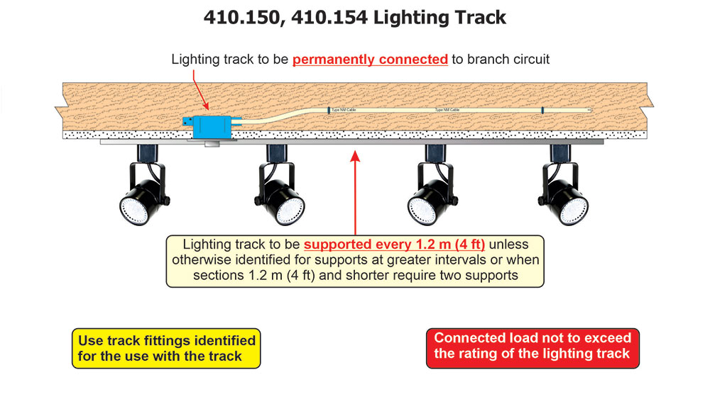
Track lighting (except for dwelling and hotel/motel guestrooms). Add 150 VA for every 2 ft (or fraction) of track to the feeder/service load; for multicircuit track, the load is considered equally divided among the track circuits [220.46(B), Track Lighting]. Note this explicitly on the one-line so it isn’t missed late in design.
Articles 404 & 406 — Controls and the 2026 move
Article 404, Switches, establishes the standards for switch construction, ratings, terminations, grounding, and installation. In lighting work, two aspects are most important: (1) where a neutral is needed at the switch for modern controls, and (2) how snap switches and electronic controls must be terminated and listed. Controls are currently in Article 404 and will move to 406 Part III in 2026 (device-type switches, dimmers, electronic control switches).
For 2023: provide a neutral at many switch locations serving lighting controls (404.2(C), with some exceptions); ensure device markings and terminations are respected—push-in terminals on snap switches are generally limited to 14 AWG Cu/15 A unless specified otherwise, and CO/ALR governs aluminum compatibility (404.14(D)); and do not recondition damaged switches or dimmers (404.16). Start pre-tagging specifications so citations change from 404.x → 406.3x–.4x when your AHJ adopts 2026.
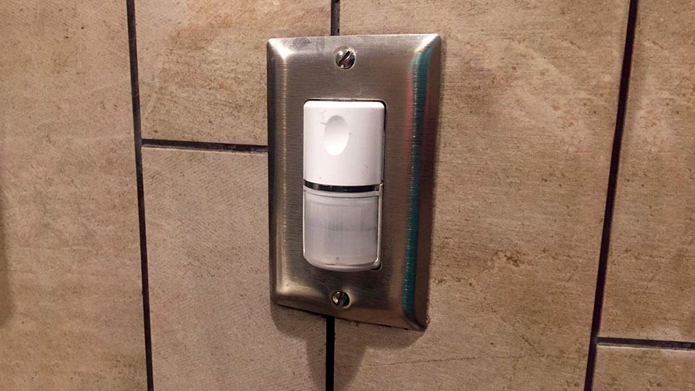
On the neutral: Section 404.2(C), Switches Controlling Lighting Loads, still requires a grounded (neutral) conductor at many lighting switch locations so that electronic controls (occupancy/vacancy sensors, timers, smart switches) have a return path. There are specific exceptions, but the goal is to prevent using equipment grounding conductors as current-carrying returns and to make retrofits easier. If your control needs line-to-neutral power in standby, the box must have a neutral unless you meet one of the limited exceptions—plan cable types and box fills accordingly.
Regarding terminations and ratings: the 2023 cycle refined snap-switch rules. New Section 404.14(D), Snap Switch Terminations, explains that push-in (screwless) terminals on snap switches are limited to 14 AWG copper conductors on 15-ampere circuits unless the device is specifically listed and marked otherwise. It also links conductor compatibility to CO/ALR markings when aluminum or copper-clad aluminum is used. In short: verify the device markings before connecting anything other than 14-AWG copper on stab-ins, and check for CO/ALR markings if aluminum conductors are involved.
Reconditioned Equipment: Section 404.16, Reconditioned Equipment, (new in 2023) explicitly states that lighting, dimmer, and electronic control switches—and snap switches of any kind—are not allowed to be reconditioned. If a device is damaged by fire, water, or smoke, it must be replaced; cleaning and returning it to service are not permitted. This language clarifies a common gray area and provides inspectors with clear guidance.
Looking ahead to 2026
A major organizational change moves device-type switches (such as wall switches, dimmers, and electronic control switches) from Article 404 to Article 406. Article 404 will continue to cover larger general-use switches, pullouts, fused disconnects, and circuit breakers used as switches. For plan reviewers and spec writers, expect section renumbering in your standard details; the technical requirements for device-type switches will largely remain the same in the new 406 Part III.
Article 410 — Installation realities
Article 410, Luminaires, Lampholders, and Lamps, covers listing, identification, support, connections, and location-based restrictions for luminaires.
Provide proper support/means [410.36] and use boxes identified for the load; fan-light combos require a paddle-fan-rated box [314.27(C)]. Splices belong in accessible enclosures/compartments [300.15]. Converting to LED with a retrofit kit demands a listed kit installed per instructions [410.6, 110.3(B)], and a luminaire retrofitted per kit instructions is not “reconditioned” under 410.2. (This is a common punch-list item in modernization projects.)
Location rules regularly hit commercial work: tub/shower zones in hotels/dorms/locker rooms [410.10(D)], closet restrictions in residential-type spaces within mixed-use [410.16], and wet/damp ratings matched to the installed environment [410.10(A),(B)]. Germicidal (UV-C) luminaires got dedicated requirements in 410 Part XVII (2023): they must be listed/identified as germicidal equipment and installed per markings/instructions.
New: germicidal irradiation luminaires. Recognizing wider adoption after the pandemic, the 2023 NEC added Part XVII, Special Provisions for Germicidal Irradiation Luminaires, in Article 410 for Ultraviolet (UV-C) germicidal irradiation luminaires. It requires these products to be listed and identified as germicidal equipment, installed according to the equipment markings and manufacturer instructions, and it establishes minimum safety provisions that help AHJs, designers, and facility staff manage occupant exposure and maintenance. If you’re specifying upper-room UV-C or in-duct UV-C, explicitly mention compliance with Part XVII of 410 in your submittals.
Article 700 — Emergency lighting & controls
Emergency/egress lighting requires tight coordination with Article 700. Identify and separate emergency wiring [700.10, Wiring, Emergency System], provide fire protection of circuits where required [700.10(D)], and ensure the emergency source/transfer meets 700.12, General Requirements (including 700.12(H) for battery-equipped emergency luminaires). Performance is enforced in 700.16, Emergency Illumination (no single failure leaves an area in total darkness). Use UL 924-listed control devices consistent with the Article 100 terms (ELCD/ALCR/BCELTS) so normal luminaires can be directly controlled to emergency levels on loss of normal power. Maintain selective coordination [700.32, Selective Coordination] and re-evaluate it when devices are replaced/modified). Provide SPDs at emergency distribution equipment per 700.8, Surge Protection. (The 2023 NEC also recognizes Class 2-powered emergency lighting and requires separation from non-emergency Class 2 circuits—coordinate your PoE/low-voltage designs accordingly.)
Occupancy/System Quick Hits (Commercial)
Commercial garages (Art. 511). The classification of floor areas, pits, and ceiling voids depends on fuel type and ventilation: for gasoline and other heavier-than-air fuels, floor areas and pits are classified according to 511.3(C), Repair Garages, Major and Minor. For example, without the required ventilation, the entire floor area is Class I, Div. 2 up to 18 inches above the floor, and pit areas may be classified as Class I, Div. 1. When specified ventilation rates are met, the classification can be reduced. When lighter-than-air fuels such as CNG or hydrogen are involved, the ceiling zone within 18 inches of the highest point is considered for classification under Table 511.3(D). It can be unclassified if ceiling exhaust is provided at ≥1 cfm/ft² with pickup within 18 inches of the high point, or classified as Class I, Div. 2 if such ventilation is not present [511.3(D)]. Any lighting within a classified layer must be installed per Article 501 by direct reference in 511.4(A), Wiring Located in Class I Locations, while wiring and equipment above the classified envelope must comply with 511.7 regarding methods and equipment placement.
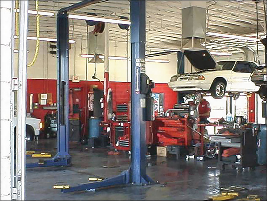
In practice, designers try to keep luminaires outside the classified volume or use sealed, pressurized, or explosion-proof fixtures identified for the Division or Zone. They also coordinate ventilation and detection systems so that adjacent areas can be treated as unclassified where permitted by the code (e.g., spaces properly isolated or mechanically ventilated at specified air-change rates). Small boundary shifts during remodels—such as moving a luminaire a foot or two—can change its classification from “damp-location” to “Class I.”
Aircraft hangars (Art. 513) define classified zones near floors or ceilings based on fuel properties and ventilation. The first step in lighting is to determine the hazardous envelope per 513.3, Classification of Locations, and its subsections (e.g., below-floor pits, vicinity of aircraft, and areas that are ‘suitably cut off and ventilated”). If an area is properly isolated and ventilated—for example, with mechanical ventilation at or above the required rate—adjacent rooms can be considered unclassified according to 513.3(D), Areas Suitably Separated and Ventilated. This often allows the use of standard luminaires outside the envelope. Within the classified volume, fixtures and wiring must meet Class I standards and be installed in accordance with Article 501/505 (i.e., wiring per Part II and equipment per Part III). Seals are necessary at boundaries to prevent vapor migration (513.9, Sealing). Outside or above the classified limits, the nonhazardous parts of the hangar follow 513.7, Wiring and Equipment Not Installed in Class I Locations, which covers fixed wiring methods and equipment for unclassified areas. This is where many designers place luminaires to avoid explosion-proof construction when space and clearances permit. Specific hangar lighting details also apply: metal-shell, fiber-lined lampholders are not allowed for fixed incandescent lighting [see 513.7(D)], and any portable lighting used for maintenance inside the hangar must be equipped with a heavy-duty cord and an equipment grounding conductor, and be properly rated for the location [513.10(E)(1)].
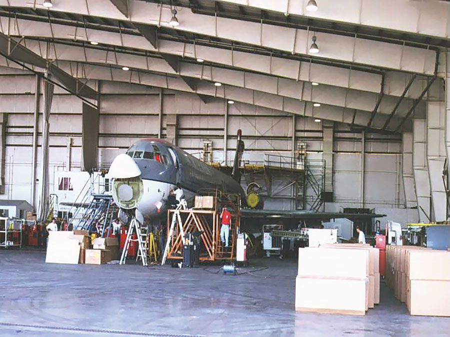
Additionally, GFCI protection for personnel is required for applicable receptacles used for maintenance and portable lighting [513.12, GFCI Protection for Personnel]. Practically, the lighting approach is to keep luminaires outside the classified volume whenever possible, or use equipment rated for the appropriate Class/Division when inside it. Also, coordinate detection and ventilation controls that can “declassify” parts of the space under 513.3(D), allowing a wider range of luminaires to be used.
At motor fuel dispensing facilities (Art. 514) and bulk storage plants (Art. 515), the Code defines hazardous (classified) boundaries around dispensers, tank vents, and transfer points—using figures and tables and text—so designers can position (or keep) luminaires outside these boundaries whenever possible [514.3(B), Classified Locations, and Tables 514.3(B)(1)–(2); 515.3/Table 515.3]. Luminaires inside a classified zone must be suitable for Class I use and installed according to hazardous-location rules by referencing Articles 501/505 [514.4; 515.4, Wiring and Equipment Located in Hazardous (Classified) Locations].
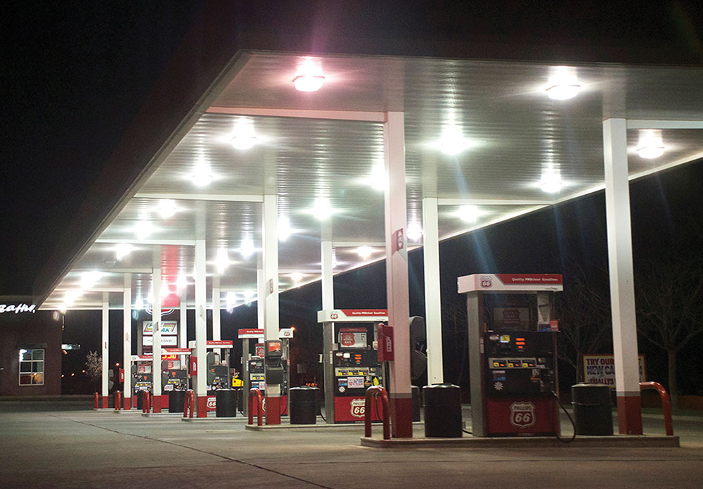
Luminaires outside or above the classified boundary can be ordinary-location equipment if they stay clear of the classified area and are installed to prevent vapor migration, such as by providing necessary sealing at raceways and fittings [514.9, Sealing]; Article 515 also covers wiring and equipment installed above classified locations [515.7, Wiring and Equipment Above Hazardous (Classified) Locations]. Both articles explicitly refer back to Articles 500/501 (or 505) for equipment selection and wiring methods [514.4; 515.4], and Article 514’s tables and figures serve as the primary references for classifying dispenser areas on plans [514.3(B), Tables 514.3(B)(1)–(2)]. Therefore, your plan review should always include a lighting and controls overlay on the classified plan to verify luminaire type, location, and sealing requirements at boundaries.
For spray application, dipping, coating, and printing processes (Art. 516) involving flammable or combustible materials, luminaires in spray areas must be identified for the hazardous classification created by the process—for example, the interior of spray booths/rooms is Class I, Division 1 (or Zone 1/21) [516.5(C)(1)], and areas within 3 ft of booth/room openings are Class I, Division 2 (or Zone 2/22) [516.5(D)(2)]; adjacent “unenclosed” spray areas have broader Class II/Div. 2 envelopes shown in [516.5(D)(1)]. All wiring and equipment located within the hazardous (classified) locations defined in 516.5 must comply with Article 501 (or 505 for Zones) for vapors [516.6(A), Wiring and Equipment-Vapors]; where combustible powders/dusts are involved, selection/deployment is coordinated with Article 502 requirements (as referenced by NFPA 33’s directive to meet NEC 500/501/502/505/516) [NFPA 33 6.2.1].
In practice, designers often place fixtures outside the spray room/booth with listed viewing windows or use luminaires rated for the interior classification; where luminaires are mounted to the wall/ceiling and separated from the spray area by glass yet lie within a Class I, Div. 2 zone, they must be suitable for that location and be serviceable from outside the spray area [516.6(C)(2), Illumination]. Because the classified envelope can change with process and airflow—for example, provisions for recirculated exhaust and door interlocks explicitly alter whether certain volumes remain classified [516.5(D)(4)(2)–(3), Enclosed Spray Booths and Spray Rooms]—inspectors should verify at turnover that the installed luminaire type and location still match the actual classified boundaries shown on the final ventilation/process drawings.
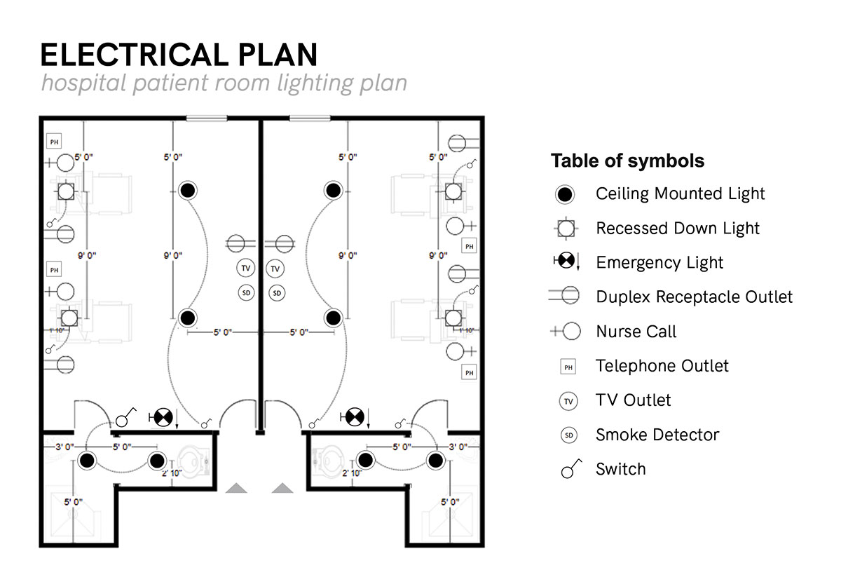
Article 517 — Health Care Facilities
In Article 517, Health Care Facilities, requirements for the Essential Electrical System (EES) regulate how egress and patient-care lighting are powered, separated, and controlled during a utility outage (517.29, Type 1 Essential Electrical Systems; 517.30, Sources of Power). Lighting that serves the life safety branch—corridors, egress, exit discharge, and other code-required illumination—must meet Article 700 fundamentals except as modified by 517.26, Application of Other Articles, which specifies certain exceptions to Article 700 for health care facilities (517.26). Critical-branch lighting supplies task illumination for patient care tasks, procedure rooms, nurse stations, and similar areas [517.34(A), Task Illumination, Fixed Equipment, and Select Receptacles].

The main point for lighting design is circuiting discipline: put egress luminaires on the life-safety branch [illumination of means of egress — 517.33(A), Illumination of Means of Egress], place task lighting on the critical branch [517.34(A)], and keep the life-safety and critical branches completely independent of all other wiring and of each other [separation — 517.31(C)(1), Separation from Other Circuits].
Where the Code requires automatic operation, the life-safety and critical branches must be automatically restored within 10 seconds after losing normal power [branches requiring automatic connection — 517.31, Requirements for the Essential Electrical System; see also Type 2 EES timing in 517.32(B), Life Safety and Critical Branch Used in a Type 2 EES]; coordinate any automatic control features to ensure emergency illumination is not disabled during a power loss [by applying 700.12/700.16 via 517.26]. Submittals should clearly specify UL 924–listed emergency lighting control devices (use Article 100 terminology for ELCD/ALCR/BCELTS), the automatic transfer sequence and timing [517.30; 517.31], branch separation/identification [517.31(C)(1)(a)], and how any battery-equipped emergency luminaires or unit equipment support the EES [700.12(H)].
Article 518 — Assembly Occupancies
Article 518 applies to places of assembly other than theaters and performance areas (which are covered under Article 520) [518.1; see also 520.1]. For lighting, two practical principles are emphasized: first, the Code requires reliable illumination of workspaces around fixed service equipment, switchboards, switchgear, panelboards, or motor control centers installed outdoors that serve the assembly occupancy, and it prohibits “automatic-only” control of this illumination [518.6, Illumination]; second, wiring methods in public areas must be resistant to damage or tampering, which is why fixed wiring in assembly occupancies is limited to metal raceways, flexible metal raceways, nonmetallic raceways encased in at least 2 inches of concrete, or Type MI/MC/AC cable (and Class 2/limited-energy systems follow similar fixed-wiring rules) [518.4(A), (B)]. Designers often separate egress and entry lighting controls from ambiance systems so automatic strategies (such as daylight and occupancy sensors) do not leave work areas dark when illumination is needed—something inspectors frequently verify against 518.6 during final testing.
Articles 520–540 — Entertainment Venues, Studios, Remote Locations, and Projection Rooms
Article 520 covers theaters, the audience areas of motion picture and TV studios, and similar performance spaces. When only part of a building is a theater, it applies only to that portion [520.1, Scope]. Stage lighting equipment unique to these spaces—including stage switchboards, dimmer or relay racks, and their feeders—is governed in 520.26 and 520.27. Portable stage switchboards are detailed in Part IV [520.50–520.53], while production portable distribution (multicables, stringers, etc.) is covered in Part V [520.61–520.68]. These require extra-hard usage cords for portables and allow hard-usage types only in protected applications [520.68(A)(1)–(2)].
Single-pole separable connectors used with stage feeders and distribution are limited by 520.54(H) regarding the number of interconnections and must comply with 406.13. Stage lighting hoists are addressed in 520.40, Stage Lighting Hoists, and fixed wiring to battens, catwalks, and raceways must use the methods listed in 520.5, Wiring Methods, such as metal raceways or MI/MC/AC with an EGC. Since lighting loads are typically continuous and highly dimmed, overcurrent protection and ampacity follow Article 520’s special rules, for example, Table 520.44(C)(2)(1) and (2)(2) for listed cords, which modifies the general application of 400.5 in these occupancies. Lastly, inspectors check for proper support and strain-relief on connectors and drops—multiple branch-circuit cable connectors must not transmit tension to terminations [520.67, Multipole Branch-Circuit Cable Connectors].

Article 530 applies to motion picture and television studios and remote locations staffed by qualified persons [530.1—scope, 2023 rewrite], and it specifically covers portable power distribution and single-pole separable connectors (such as the cam-lock/Posi-Lok hardware common to production lighting) [530.22(A), Stage Set Wiring]. Recent updates highlighted GFCI requirements where the public or wet processes are involved in support areas, although some outdoor production circuits remain exempt—so your design notes should clearly specify where GFCI is required and where it is not under Article 530 (530 scope commentary; public/wet support-area GFCI focus). Overcurrent protection is prescriptive: portable stage-cable branch circuits are protected according to 400.5 rules [530.23(A)], while feeder cables have the established “up to 400% of Table 400.5(A)(2) ampacity” setting [530.23(B)]—a requirement often verified by AHJs through documented details on the distro one-line. In practice, production lighting depends on cam-locks, feeders, and portable distribution used by qualified personnel, with explicit equipment listings, field labeling, and bonding/grounding provisions (including new language for production vehicles and trailers integrated into the distribution system) documented on submittals.
Article 540 (projection rooms) is narrow but highly specific: projection booths must follow particular working-space and wiring rules—each projector requires clear working space (not less than 30 inches on each side and at the rear) [540.12, Work Space], and associated equipment (motor-generator sets, rectifiers, transformers) is restricted in where it can be located and how it’s constructed/ventilated if placed in the booth [540.11(A), Motor Generator Sets, Transformers, Rectifiers, Rheostats, and Similar Equipment]; panelboards and other overcurrent devices not serving the projection equipment are prohibited in the booth [540.11(B), Switches, Overcurrent Devices, or Other Equipment]. Feeders for professional arc/xenon projectors must meet minimum conductor size and ampacity rules—not smaller than 8 AWG and with ampacity at least equal to the projector’s nameplate current (540.14, Conductors on Lamps and Hot Equipment)—while incandescent-type projectors follow the normal branch-circuit rules. When projection rooms are used in modern venues, verify luminaire placement against booth sightlines and the 540.12 clearances, and ensure the booth’s working-space illumination and disconnect/overcurrent device locations comply with 110.26(D) and 540.11(B), respectively.

Article 525, Carnivals, Circuses, Fairs, and Similar Events, bridges temporary power and public assembly [525.1]. Temporary lighting and receptacles are generally GFCI-protected per 525.23(A), but egress lighting may not be GFCI-protected—to avoid dark exits from nuisance trips—per 525.23(C). Locking-type receptacles that are not accessible from grade and used only to facilitate quick disconnect/reconnect are not required to be GFCI-protected per 525.23(B) (spell this out on the one-line so inspectors see which outlets are exempt). And if GFCI protection is provided by GFCI receptacles on branch circuits using flexible cord, the GFCI device must be listed/labeled/identified for portable use per 525.23(D). Your one-line and receptacle schedules should clearly distinguish these cases for the AHJ.
Articles 545–547, 550–555 — Manufactured/Relocatable, Agricultural, Mobile/RV, Floating/Marina
Article 545 covers manufactured buildings and relocatable structures [545.1; 545.2; Part II—545.20]. Factory-installed luminaires must be listed, used according to their labeling and instructions, and suitable for the environment [410.6; 110.3(B); 110.11]. Field connections, feeders, and interconnections are made using approved wiring methods and listed systems for manufactured buildings [545.4(A), Methods Permitted], with Chapter 1–4 rules still applicable. When units are ganged, any lighting branch circuits or control conductors crossing module seams must use tested, identified, and listed interconnection fittings permitted to be concealed and capable of withstanding vibration and minor relative movement [545.13, Component Interconnections]; where each module has a factory panelboard, separate feeders are allowed [545.22(B), Branch-Circuit Protective Equipment and Panelboards]. Provide physical protection and secure components properly where required—especially in enclosed construction—per 545.4(B).
Article 547 (agricultural buildings) recognizes the harsh, damp, and dusty conditions common in livestock and produce environments [547.1(A)–(B)]. Lighting fixtures and wiring methods in these spaces must be suitable for the environment—use enclosures and fittings that prevent dust and moisture from entering and resist corrosion [517.31(A), Minimize the Entrance of Dust]. Install luminaires to reduce the entry of dust and foreign matter, and protect them from physical damage; when luminaires are exposed to washdown or condensation, they must be listed for wet locations [547.31(C), Exposed to Water]. Since concrete-on-grade confinement and routine washdowns can cause shock hazards, apply equipotential planes and bonding in livestock areas and connect them to the grounding system [547.44(A)–(B), Equipotential Planes and Bonding of Equipotential Planes, 2023 numbering]. Also, coordinate the distribution-point design to lower the neutral-to-earth voltage across the site [547.42 and its Informational Note]. Many designs favor sealed LED luminaires with corrosion-resistant (often nonmetallic) hardware to meet the dust, corrosion, and wet-location requirements [547.31(A)–(C)]. Finally, verify GFCI assumptions against the actual equipment used and any local amendments—Article 547 directs you to the general GFCI rules in 210.8(B) for non-dwelling areas, and the receptacle section of the agricultural article [e.g., 547.28 in 2023 organization; formerly 547.5(G)] clarifies how GFCI applies within these occupancies [547.28; 210.8(B)].
For manufactured/mobile home parks (Art. 550), factory-installed luminaires must be listed/labeled for the environment and used per instructions, and field connections/feeder interconnects must follow Art. 545/Chapter 1–4 basics [listing/labeling: 110.3(B); 410.6]. Lighting load for a manufactured/mobile home is figured at 3 VA/ft² using 220.41 via 550.18(A)(1), Lighting, Small-Appliance, and Laundry Load/Lighting Volt-Amperes, with small-appliance and laundry loads added separately per 220.52(A)–(B); bathroom luminaires that include a general-purpose receptacle must have that receptacle GFCI-protected [see 210.8(A) sentence covering receptacles integral to ceiling luminaires/ceiling fans]. Service/disconnect placement follows 550.32 (outdoor, readily accessible, within sight of the home).
For RVs and RV parks (Art. 551), site equipment (“pedestals”) must be listed as recreational vehicle site supply equipment and comply with 551.77(A)–(F), with site receptacle mixes per 551.71, Type Receptacles Provided (e.g., minimum 70% 30 A and 40% 50 A for new parks, plus a 20 A receptacle). Lay out pedestals per 551.77(A), Location, and maintain working space clearances per 110.26 around electrical equipment; coordinate pedestal locations so common-area lighting and signs don’t violate those clearances. In short, manufactured-home lighting uses the dwelling 3 VA/ft² method [550.18(A)(1) to 220.41], while RV parks hinge on listed pedestals, required receptacle mixes [551.71], and proper location/clearances [551.77, 110.26].
“Floating buildings” previously discussed in Article 553 were moved to Article 555 during the 2020 cycle (now Part III—Floating Buildings). This consolidates regulations for docks and floating structures—including floating buildings—into one section (2020 change). For lighting on docks and floating structures, the Code emphasizes: ground-fault protection of equipment (GFPE)—for example, feeders on docking facilities must have GFPE ≤ 100 mA [555.35(A), Feeder], while shore-power receptacles require individual GFPE ≤ 30 mA [555.35(B)(1)], and other docking-facility outlets must use GFCI within specific ratings [555.35(B)(2), (C)]. It also calls for coordination with liquid-fuel systems, as wiring and equipment serving fuel-dispensing at marinas must comply with Article 514 (555.11), and repair areas with flammables are governed by Article 511 [555.12]. Service equipment must be located onshore—not on the floating structure—and at least 5 ft horizontally away from it (555.4, Location of Service Equipment). Luminaires and wiring should be rated for the environment and arranged to handle movement and corrosion—refer to wiring-method and protection rules in 555.34 (wet-location wiring methods; protection up to 8 ft above docks) and luminaire securing/underwater-luminaire limits in 555.38(A)–(B). Lastly, coordinate fixture coatings and hardware with the electrical datum plane (EDP) to keep equipment above rising water: the EDP definitions and clearances are in 555.3, and equipment must not be installed below the EDP in 555.30(A), General. In practice, circuits that supply pier lighting often include branch or feeder GFPE between 30 mA and 100 mA, depending on whether protection is needed at the receptacle/circuit level (30 mA) or feeder level (≤ 100 mA) under 555.35.
Article 600 — Electric Signs and Outline Lighting
Lighting teams often overlook Article 600, Special Equipment, but it has two important implications: (1) a dedicated 20 A branch circuit and sign/outline-lighting outlet are required at each entrance to every commercial tenant space accessible to pedestrians per 600.5(A), Required Branch Circuit; and (2) a within-sight disconnect (or a lockable alternative in the specified location) must be installed where the feeder/branch enters the sign enclosure or pole per 600.6(A)(1), Location—At Point of Entry to a Sign Enclosure (or pole). These requirements are important even when the sign vendor is considered “by others”—plan reviewers should verify that the outlet and circuit are shown on the drawings, and inspectors should check for the disconnect at the correct physical point of entry.
Article 620 — Elevators, Escalators, Moving Walks
Lighting in elevator machine rooms, control rooms/spaces, and pits has specific branch-circuiting rules: in machine/control spaces, lighting outlets must be on a branch circuit separate from receptacles [620.23(A), Separate Branch Circuits] with the lighting switch at the point of entry [620.23(B), Lighting Switch]; in pits, lighting must be on a branch circuit separate from pit receptacles and shall not be connected to the load side of the GFCI that serves those receptacles [620.24(A), Separate Branch Circuits, 620.6, Ground-Fault Circuit-Interrupter Protection for Personnel]. Cab lighting and ventilation are supplied by a separate car-lighting branch circuit (which may also feed certain listed low-power accessories) per 620.22(A), Car Light Receptacles, Auxiliary Lighting, and Ventilation. During inspection, trace the pit circuiting to verify the luminaire remains energized if the receptacle GFCI trips [620.24(A), Separate Branch Circuits].
Article 645 — Information Technology Equipment Rooms
Article 645’s special wiring and disconnect allowances apply only if the IT room meets all conditions in 645.4(1)–(6) (construction, dedicated HVAC, listed ITE, access limitations, fire-resistance, and “only-related-equipment” in the room); otherwise the general Chapter 1–4 rules govern the installation (645.4, Special Requirements for Information Technology Equipment Room). When 645 is used, lighting design must respect the disconnecting means/EPO scheme in 645.10, Disconnecting Means, and you should ensure egress lighting is not disabled by EPO activation since the 645.10 disconnect is intended to shut down electronic IT equipment, not the room’s lighting circuits. Under raised floors, any indicators or luminaires (if provided) and their branch circuits must follow the permitted wiring methods and cable/cord rules in 645.5—notably 645.5(E), Under Raised Floors, for wiring under raised floors (support/secure, DP/listed cable where applicable, protected floor openings, etc.). If the 645.4 conditions aren’t met, delete the 645 allowances from your design narrative and apply standard Chapter 1–4 wiring methods throughout.
Articles 680–682 — Pools, Spas, Fountains, and Bodies of Water
Near water, Articles 680 (pools/spas/fountains) and 682 (natural/artificial bodies not covered by 680) still govern commercial landscapes. Article 680 establishes the requirements for pool, spa, and fountain lighting. For permanently installed pools, luminaires, lighting outlets, and ceiling-suspended (paddle) fans located above the water or within specified horizontal distances from the water’s edge must comply with strict height, clearance, and protection rules [see 680.22(B), Luminaires, Lighting Outlets, and Ceiling-Suspended (Paddle) Fans]. For example, new outdoor installations ≥12 ft above water within the 0–5 ft zone, along with additional provisions for 5–10 ft “adjacent areas.” GFCI or SPGFCI protection is needed where applicable [680.22(B)(1)–(4), (6)]. Recent editions also widened GFCI coverage to include receptacles near pools at higher voltages—any receptacles within 20 ft are GFCI-protected up to 250 V, with SPGFCI where required [680.22(A)(4), GFCI and SPGFCI Protection]. Underwater luminaires must be installed 4–18 in. below the water’s normal level [680.23(A)(5)]; they must be removable to the deck for servicing, with enough cord length [680.23(B)(6)]; and must connect through listed forming shells and junction boxes or enclosures using approved wiring methods [680.23(B)(1)–(3), 680.24]. Bond all necessary metal parts— including metallic forming shells, according to 680.23(B)(5), Luminaire Bonding, and the equipotential bonding rules of 680.26, Equipotential Bonding. These rules work together to keep people and electricity separated by distance, isolation, and quick protection.
Article 682 covers wiring and equipment in or near natural or man-made bodies of water not included under 680 (e.g., stormwater basins, fish ponds, irrigation channels) [682.1, Scope]. The electrical datum plane (EDP) defines the vertical limits that control equipment placement and clearances [682.5, Electrical Datum Plane Distances]. Within the EDP region, receptacles and other outlets must be GFCI-protected per 682.15, Ground-Fault Protection, and the GFCI (or other required ground-fault protective device) must be located at least 12 inches above the established EDP. These requirements are in addition to 210.8, Ground-Fault Circuit-Interrupter Protection for Personnel. Electrical equipment and enclosures must be specifically approved for their intended location, and no part of any enclosure not rated for operation while submerged may be located below the EDP [682.10, Electrical Equipment and Transformers].
Similarly, electrical connections not intended for operation while submerged must not be below the EDP; if connections are below the EDP, they must be of a type listed or identified for submersion, with wiring methods following Part III [682.12, Electrical Connections, 682.13, Wiring Methods and Installation]. In practice, lighting equipment in these areas must have environmental ratings suitable for exposure and be installed above the EDP unless specifically listed for submersion. These Article 682 rules supplement the general GFCI provisions of 210.8, GFCI Protection for Personnel, and are easy to overlook in civil-led site packages.
2023 Highlights (Commercial)
- Article 100 added emergency-lighting device/luminaire terms; 700 reorganized for modern sources/controls; Class 2 emergency lighting separation recognized.
- 210.70 tightened battery-only control and clarified additional required locations.
- 410 clarified bathtub/shower limits (fan + light kit),
- Added special provisions for germicidal radiation luminaires in Article 410, Part XVII.
2026 Outlook (Commercial)
- Device-type switches/dimmers migrate to 406 Part III (update details/schedules/spec cites)
- Article 220 content renumbering (e.g., the non-dwelling lighting table trends toward 220.42(A)) will change your references even if the underlying math remains the same.
- Continued polish of emergency-lighting terminology across 100/700.
Field Checklist (Commercial)
- Declare Table 220 method vs energy-code alternative, show track/show-window adders, and apply 125% for continuous lighting.
- Provide neutrals at control boxes; verify device markings (push-in limits, CO/ALR).
- Emergency distribution: separation/identification, SPDs, selective coordination, and UL 924 controls with “no total darkness.”
- Special occupancies: show classified boundaries on the RCP/one-line; specify fixture listings and seals; call out 518.6 working-space lighting; include sign outlets/disconnects (600.5/.6); elevator pit lighting not on GFCI load side.