In Part I of the series, we covered the prescriptive placement requirements for overcurrent protective devices (OCPD). Specifically, 2023 NEC Section 240.21. For Part II we will take a deeper dive on feeder taps, and the rules for feeder taps.
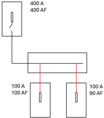
In the 2023 NEC, Section 240.21 requires OCPDs to be placed in each ungrounded conductor at the point where the conductors receive their supply. This assures the total circuit current is forced through the OCPD. What if the OCPD did not protect a conductor at its ampacity? Would this violate 2023 NEC Section 240.4? For example, a four-hundred-ampere fuse supplies 500 kcmil copper conductors, which terminate within a metal wireway. From the metal wireway, another set of conductors supplies several 100-ampere disconnects. [See Figure 1.] What if the conductors from the wireway to the 100-ampere disconnect were smaller than 500 kcmil? Does the NEC permit this? Yes, the NEC does permit this where all applicable conditions laid out in 2023 NEC Section 240.21(B) have been satisfied.
Let’s begin with a look at the 2023 NEC definition for tap conductor. The NEC defines a tap conductor as “a conductor, other than a service conductor, that has overcurrent protection ahead of its point of supply that exceeds the value permitted for similar conductors that are protected as described elsewhere in 240.4.” Typically, conductors are protected at their ampacity to comply with 2023 NEC Section 240.4. List item (3) of 2023 NEC Section 240.4(E) permits tap conductor installations. Feeder taps receive the full range of overcurrent protection from not one but two OCPDs. [See Figure 2.]
Protecting Feeder Taps
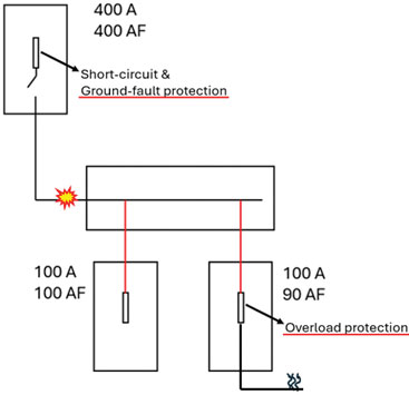
Feeder taps will receive short-circuit and ground-fault protection from the OCPD supplying the feeders and overload protection from the OCPD, to which the feeder taps also terminate. To ensure feeder taps are provided with short-circuit and ground-fault protection from the upstream OCPD supplying the feeders, the tap conductors must be of low impedance. Compliance with 2023 NEC Section 240.21(B) assures the tap conductors have a low impedance.
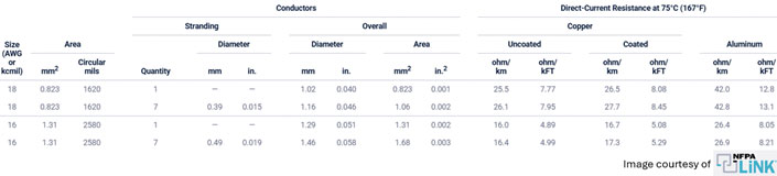
Recall, as the length of a conductor increases, the DC resistance also increases. Where the area of the conductor increases, the DC resistance decreases. This can also be stated as, conductor length & resistance are proportional to one another, while conductor area & resistance are inversely proportional to one another. This is also displayed when viewing 2023 NEC Chapter 9 Table 8. See Figure 3.
Let’s review two of the more common feeder tap applications, commonly referred to in the industry as the ten-foot and twenty-five-foot rules. Where feeder taps are located indoors in lengths up to ten feet, they must comply with list items (1)-(4) of Section 240.21(B)(1). Complying with Section 240.21(B)(1)(4) will ensure the tap conductors are of low impedance, which guarantees the feeder’s OCPD to clear any short circuits or ground faults. Section 240.21(B)(1)(4) can sometimes, but not often, require a conductor of greater ampacity than the ampere rating of the overcurrent device to which the taps terminate, too. This can be the result of some simple math required by the Section, which we will cover shortly. Complying with Section 240.21(B)(1)(1) will ensure the tap conductors are provided with overload protection. Comparing 240.21(B)(1)(1) to 240.21(B)(1)(4) is what I call the VS scenario when teaching apprentices. Whichever results in the higher ampere rating will dictate the feeder tap size. See Figure 4.

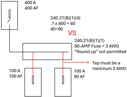
Let’s go over a practical example together. What size indoor feeder tap conductors are required? The tap conductors are less than 10’ in length and leave the enclosure where the tap is made. The feeder supplying the tap conductors is protected by a 400-ampere fuse, the tap terminates to a 90-ampere fuse, and all terminations are rated at 75 degrees Celsius. Section 240.21(B)(1)(1) is what I call the “duh rule”, essentially, in this example, the tap needs to have an ampacity greater than or equal to 90 amperes. It is very important to note that Section 240.21(B) of the 2023 NEC prohibits the “round-up rule” from being used. Specifically, the last sentence, which reads “section 240.4(B) shall not be permitted for tap conductors.” As a former inspector, I can say this was a common citation surrounding feeder tap installations. Now that we have the “duh” rule out of the way, all that remains is some simple math. For an indoor tap conductor not exceeding 10’ in length, we will need to ensure the tap has an ampacity equal to or greater than 1/10 of the feeder OCPD’s ampere rating, then select whichever ampacity is greater, 240.21(B)(1)(1) or 240.21(B)(1)(4). [See Figure 5.]
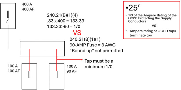
Let’s go over that same example again, but change the length of the tap conductors. What size indoor feeder tap conductors are required? The tap conductors are 15’ in length and leave the enclosure where the tap is made. The feeder supplying the tap conductors is protected by a 400-ampere fuse, the tap terminates to a 90-ampere fuse, and all terminations are rated at 75 degrees Celsius. In this example we will be comparing 2023 NEC Sections 240.21(B)(2)(2) & 240.21(B)(2)(1), see Figure 6 for the solution.
IN Summary
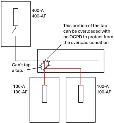
One final rule prior to wrapping this article up, let’s look at the last sentence of Section 240.21. It reads “conductors supplied under 240.21(A) through (H) shall not supply another conductor except through an overcurrent protective device meeting the requirements of 240.4.” Most in the industry put this as, you can’t tap a tap. This simple rule ensures tap conductors cannot be overloaded. See image 7 for a greater explanation. I hope you have found this article helpful and a great resource to share with those new to the electrical industry or with questions about feeder taps.