
The global electrical landscape is changing more rapidly than at any point in the past half-century. A surge in digital transformation, the rise of artificial intelligence (AI), and the push for ever-higher compute density have reshaped expectations for electrical infrastructure—especially in data centers. Once defined by modest server rooms and predictable load profiles, today’s facilities operate as large-scale electrical plants, with high-voltage distribution, modular construction, advanced cooling systems, complex grounding networks, and multilayered resiliency strategies.
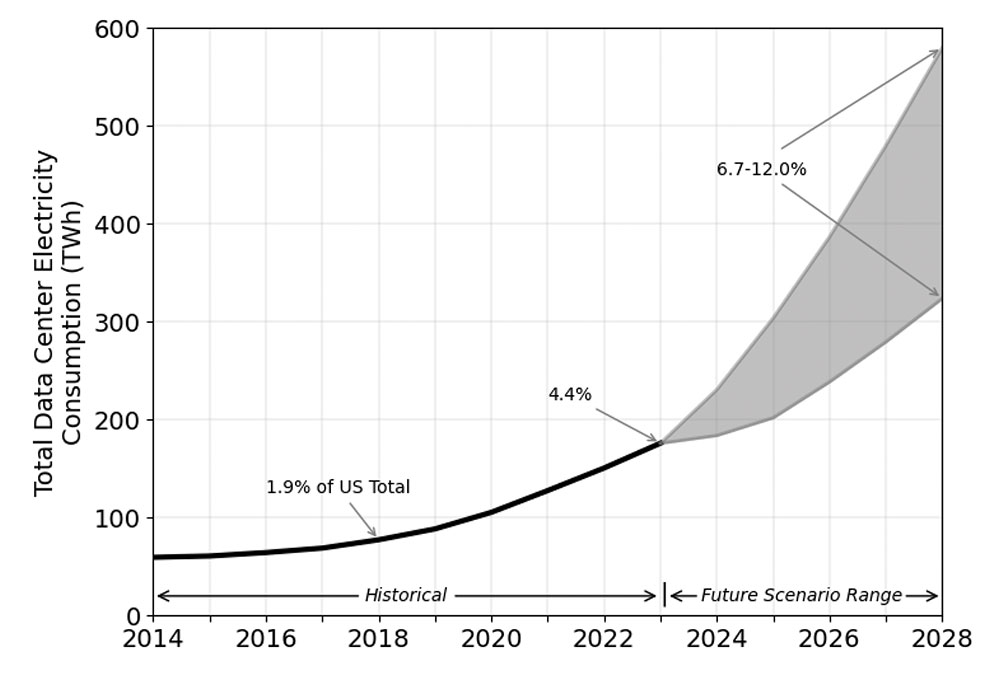
Electricity consumption reflects this shift. According to a December 2024 report by the U.S. Department of Energy, data center energy use has climbed from 58 terawatt-hours (TWh) in 2014 to 176 TWh in 2023. Projections indicate U.S. demand could reach 325–580 TWh by 2028—up to 12 percent of total national electricity generation.¹ These installations are no longer niche technology sites; they have become critical infrastructure on par with transportation hubs, hospitals, and water treatment facilities. Nearly every aspect of modern life—business transactions, 911 dispatching, medical imaging, online education, industrial automation, and real-time cloud computing—relies on their continuous operation.
As the electrical backbone of the digital world grows more complex, the National Electrical Code® (NEC®) must evolve with it. The 2026 NEC continues a multi-cycle effort to clarify, reorganize, and strengthen requirements for medium-voltage systems, conductor ampacity, overcurrent protection, grounding and bonding, emergency power, and the use of modular or non-certified equipment. One of the most significant changes is the relocation of the medium-voltage grounding and bonding rules from Article 250 into the new stand-alone Article 270—a change with major implications for data center design and inspection.
This article provides a comprehensive technical analysis of the trends driving modern data center development and the NEC provisions most critical to ensuring these facilities operate safely and reliably. It is written for Authorities Having Jurisdiction (AHJs), electrical inspectors, engineers, designers, facility managers, and contractors—professionals tasked with navigating a rapidly changing environment where innovation often outpaces traditional inspection methods.
THE EVOLUTION OF DATA CENTERS: FROM SERVER ROOMS TO HIGH-DENSITY POWER PLANTS
Twenty years ago, most data centers were simple, single-purpose facilities with power densities typically between 5 and 15 kW per rack. Their electrical systems, cooling methods, and operational needs were modest compared to today’s AI-driven environments. The growth of large-scale machine learning, cloud computing, and hyperscale platforms has turned data centers into high-density electrical facilities that resemble industrial power plants more than traditional IT rooms. These new facilities demand completely different approaches to electrical distribution, cooling, overcurrent protection, grounding, and maintenance.
- AI and GPU Clusters: The Biggest Electrical Load Shift in Decades
Artificial intelligence workloads have completely rewritten the rules. Conventional servers once consumed 5–15 kW per rack. AI compute racks today routinely exceed 300–600 kW, with leading-edge GPU training clusters approaching 1 MW per rack, tens of megawatts per row, and over 150 MW per facility. This directly affects conductor ampacity, feeder sizing, cooling equipment, grounding, equipment spacing, and emergency power system capacity.
The difference in electrical consumption between traditional digital workloads and AI-focused systems is striking. A traditional, non-AI Google search typically consumes around 0.3 watt-hours (Wh) per query. An AI query, such as one to ChatGPT, consumes significantly more power, with estimates generally ranging from approximately 3–5 Wh or more, roughly 10–20 times higher than a standard search. Traditional CPU servers typically run at a few hundred watts (for example, 300–500 watts). In contrast, servers in high-density AI training clusters, packed with multiple powerful GPUs, can exceed 10 kW per server.²
- The Rise of Medium Voltage
Large, power-intensive data centers, particularly those supporting AI and high-performance computing (HPC), are increasingly adopting medium-voltage (MV) power distribution—typically 4.16 kV, 12.47 kV, 13.2 kV, or even up to 34.5 kV within the facility—to reduce energy losses and manage massive electrical loads. MV power systems are generally defined as those that manage feeds of 1,000 to 35,000 volts (or up to 38,000 V in some contexts).
For a given amount of power, higher voltage means proportionally lower current (P = V × I). Lower current reduces resistive losses (I²R) in the power distribution system, providing a major efficiency benefit. In larger data centers, medium-voltage AC power systems—defined as systems managing feeds of 1000 to 38,000 volts—are increasingly the standard for power distribution. Distributing power at MV allows for smaller, fewer conductors and less complex infrastructure, leading to significant savings in capital expenditure (CapEx) and operational expenditure (OpEx). It also enables the use of physically smaller, more efficient equipment like MV Uninterruptible Power Supply (UPS) systems, saving valuable server room space.
Consider a 1 MW load in a large facility. Distributing that power at 4.16 kV instead of 400 or 480 V can reduce the number and size of conductors required by nearly an order of magnitude. This yields substantial savings in copper, conduit, and installation labor, reduces the physical complexity of power pathways, and simplifies switching to backup energy sources. A simplified power chain with fewer lines and conversion steps also makes it easier to connect and manage backup power, such as large-scale UPS systems or generators, and can improve overall system reliability.³ Lower current also means lower power losses due to resistance (I²R losses are proportional to the square of the current), which improves the overall efficiency of power distribution.
This shift clearly indicates a directional change in the industry, moving beyond traditional designs to meet unprecedented power demands. Typical medium-voltage levels used within facilities range from 4.16 kV to 34.5 kV, with systems up to 24 kV becoming more common in new, large-scale installations. The general design approach of using MV distribution, combined with modern switchgear and protection schemes, often results in a more reliable system with fewer potential points of failure, especially for large, high-power systems like data centers.
- Modular and Prefabricated Construction
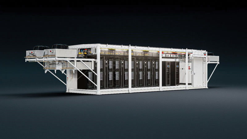
Prefabricated modular data centers (PMDCs) are manufactured off-site, transported to the location, placed on concrete pads, and connected like oversized electrical building blocks. PMDCs can range from container-sized units to large, multi-module facilities. Critical infrastructure—power distribution, cooling, and containment systems—is assembled and tested in a controlled factory environment before shipment. Once delivered, modules are set on a foundation and interconnected with each other and with site utilities. Modular Data Centers are covered by Article 646 in the NEC.
This approach offers several advantages. Deployment timelines are significantly reduced compared to traditional construction because much of the work occurs in parallel at the factory. Factory-controlled construction supports better quality assurance, consistency, and adherence to design specifications, while onsite labor and specialized installation time are reduced. Scalability is also improved; operators can add modules as demand grows rather than committing to full build-out on day one.
However, PMDCs also introduce challenges. Ensuring proper bonding and grounding continuity across all modules can be complex, especially when multiple manufacturers or design generations are involved. Internal temperatures and ambient conditions must be evaluated to confirm that conductors and equipment remain within their listing limitations. Non-certified or custom-built equipment—common in modular systems—may require field evaluation. Nameplate markings and short-circuit current ratings (SCCR) must be documented, and AHJs may struggle with limited access to internal wiring and components during inspections.
- Imported and Prototype Electrical Equipment
Supply chain bottlenecks and long lead times for standard electrical equipment (sometimes years for transformers and breakers) are forcing companies to seek alternatives, including custom-built gear, imported equipment, or non-certified components to keep projects moving. AHJs are seeing more equipment without proper listings, assemblies that have been modified after certification, and devices with undocumented field changes or unverified short-circuit ratings.
Custom equipment, prototype designs, and imported gear may not follow typical North American listing practices. Any substantial modification made in the field, such as changing bus configuration, replacing breakers, or altering enclosure openings—may invalidate the original listing, requiring a new evaluation. Where SCCR is affected, fault-current ratings must be recalculated and verified. In response to these challenges, AHJs are increasingly relying on special inspections and field evaluations by qualified organizations to determine if unlisted or modified equipment can be safely installed and operated. This is an essential safety measure when standard certification is not present.4
- Extreme Redundancy Requirements
Achieving “five nines” (99.999%) or greater uptime—no more than 5.26 minutes of downtime per year—requires extensive redundancy and robust infrastructure design, which inherently adds complexity to electrical engineering and NEC compliance. Systems must be designed to be fault-tolerant and to support concurrent maintenance without impacting critical operations. The use of redundant systems (N+1, 2N configurations), dual power paths (A/B feeds), and concurrent maintenance capabilities are standard industry practices for critical facilities like data centers.
- Redundant UPS systems protect loads from power sags, outages, and spikes, often using N+1 or 2N configurations that duplicate critical components.
- Dual power paths (A/B feeds) provide separate, independent distribution paths so that failure of one does not affect the other.
- Paralleled switchgear allows multiple power sources to operate together, improving reliability and permitting maintenance on individual units without a full shutdown.
- Rapid-transfer schemes using static transfer switches automatically and almost instantaneously shift loads between sources when a failure is detected.
These electrical strategies are supported by layered grounding approaches that help manage fault currents and potential gradients during abnormal conditions.
Each added layer of redundancy introduces additional complexity in applying the NEC, particularly in the areas of short-circuit protection, selective coordination, and physical separation of pathways. Designing overcurrent protective devices (OCPDs) so that only the device immediately upstream of a fault opens—without cascading outages—can be challenging in highly redundant systems, especially in the short-circuit region. Physical separation of redundant pathways is also critical; a single fire, water leak, or mechanical event should not be able to damage both power paths at once. Reaching “five nines” uptime is an extremely rigorous goal that demands careful, coordinated design and relentless attention to eliminating single points of failure.
NEC® 2026: Key Code Areas Affecting Modern Data Centers
Modern data centers involve many NEC articles, but several are especially critical in the 2026 cycle due to growing system complexity. The expansion of AI and HPC has led to much higher power densities and unique electrical characteristics, making the precise application of the NEC essential.
- Rethinking Load Calculations in the Age of AI
One of the defining characteristics of modern data centers is the predominance of extremely large, continuous electrical loads. AI servers, GPU-based compute racks, and high-density storage systems often operate around the clock at or near full capacity. These devices rely on switch-mode power supplies that introduce nonlinear loading and elevate harmonic content in feeders and neutral conductors. As a result, traditional load-calculation assumptions used in commercial occupancies no longer apply.
In the 2026 NEC, the introduction of Article 120, Branch-Circuit, Feeder, and Service Load Calculations, marks a major step forward in addressing these challenges. Previously, load-calculation rules were scattered across Articles 210, 215, 220, and 230, requiring designers to piece together the methodology. Article 120 consolidates these methods into a single, organized framework, improving usability and encouraging consistent application.
For data centers, Article 120 is especially important. Accurate load calculation is the foundation for conductor sizing, voltage-drop evaluation, OCPD selection, and redundant pathway design. Article 120 clarifies how to treat continuous loads, how to evaluate long feeder runs in large campuses, and how to calculate diversified versus non-diversified loads in redundant A- and B-path distribution systems. Once the loads are established under Article 120, designers turn to Articles 210, 215, 230, and 240 for rules on overcurrent protection, conductor ampacity, and continuous-load adjustments. The result is a more intuitive, structured approach that aligns with the realities of today’s large-scale data-center operations.
- Conductors, Ampacity, and Thermal Management
High-power facilities require careful treatment of conductor ampacity. As power densities rise, conductors may be subjected to sustained high current in elevated ambient temperatures, especially in hot aisles or in fully loaded cable trays. Larger ampacities require larger conductors, and the thermal environment often demands higher-temperature insulation types capable of withstanding continuous operation without degradation.
Article 310 remains central to determining conductor ampacity, temperature ratings, correction and adjustment factors, and terminal ratings. Designers must account for ambient temperature correction where equipment heat elevates local conditions, and for ampacity adjustment where multiple current-carrying conductors share the same raceway or cable tray. In many data centers, raceways, gutters, and busways must be sized generously to support adequate heat dissipation, and cable-tray layouts must be planned to avoid excessive bundling.
These considerations are not merely theoretical. Undersized or improperly derated conductors can overheat, damage insulation, and reduce reliability. In high-power facilities, it is standard practice to size raceways, gutters, and busways generously to support adequate heat dissipation and to carefully plan cable-tray layouts to avoid excessive bundling of cables. The 2026 NEC continues to refine ampacity rules, minimum conductor sizes, and terminal temperature ratings—provisions that are especially critical for high-power, continuously loaded data-center environments.
- Article 240 — Breaker Sizing, Protection, and Feeder Taps
Data centers depend heavily on sound overcurrent protection practices, and Article 240, Overcurrent Protection, is foundational to their safe operation. Selective coordination is a key requirement for critical operations, ensuring that the OCPD closest to a fault opens first, without interrupting power to unaffected portions of the system. In a data center, improper coordination can turn a localized fault into a facility-wide outage.
Article 240 also addresses energy-reducing maintenance switching, which supports safer work practices for personnel servicing energized equipment in large lineups. Feeder taps, governed by Section 240.21, are common in distribution galleries where smaller conductors are tapped from a larger, feeder-protected bus. Proper application of tap rules—length limits, ampacity requirements, and protection at the tap termination—is essential to ensure that tap conductors are adequately protected from fault currents.
Large equipment lineups with differing OCPD ratings require careful application of Sections 240.4 and 240.21 to ensure that all components are properly protected. In complex data-center power architectures, these details can make the difference between a controlled, localized trip and a cascading failure.
- Grounding and Bonding in a Two-Article World: 250 and 270
Grounding and bonding are among the most critical—and sometimes misunderstood—aspects of data-center design. These systems establish the fault-current return path, stabilize equipment voltages, provide a reference for surge protection, and protect personnel from shock hazards.
In the 2026 NEC, grounding and bonding requirements are now split clearly by system voltage. Article 250 governs systems below 1000 volts ac or 1500 volts dc. This includes branch circuits, feeders, low-voltage UPS outputs, PDUs, and IT-equipment bonding networks. Most traditional data-center grounding functions—such as bonding raceways, enclosures, cable trays, and power distribution units—fall under Article 250.
Article 270, new for 2026, governs grounding and bonding for systems above 1000 volts ac or 1500 volts dc. This is a major improvement, as medium-voltage grounding rules were previously mixed into Article 250. Modern data centers frequently use medium voltage for onsite distribution, making Article 270 directly applicable to incoming utility services, unit substations, generator paralleling gear, and medium-voltage distribution rings.
Article 270 clarifies system-grounding methods, grounding-electrode requirements, bonding-conductor sizing, and rules for establishing effective ground-fault current paths. It also provides guidance for installations where isolation, insulation, or physical guards may be used in place of grounding—conditions that may appear in certain medium-voltage modular systems or prefabricated components.
For AHJs, the key takeaway is that grounding reviews must now be approached in two layers: low-voltage grounding per Article 250 and medium-voltage grounding per the new Article 270. Both must be evaluated on their own terms, especially as modular data-center equipment increasingly integrates both voltage classes within a single assembly.
- Switchgear, Service Entrance Equipment, and Short-Circuit Ratings
Service entrance equipment in data centers is subjected to some of the highest fault currents found in the built environment. Large utility transformers, dual service feeds, paralleled generators, and medium-voltage distribution rings can create available fault currents exceeding 100,000 amperes. Under such conditions, short-circuit current ratings (SCCR) are not a formality—they are a critical safety requirement. If a component’s SCCR is lower than the available fault current at its terminals, the equipment could catastrophically fail during a short circuit, posing severe safety hazards and causing extensive damage.
AHJs must verify that every piece of equipment—switchboards, switchgear, busways, PDUs, UPS modules, and prefabricated skids—is either listed with a suitable SCCR or field-evaluated to document its withstand capabilities. NEC 110.3(A) and (B) remain the foundation for verifying proper installation in accordance with manufacturer instructions and listing requirements. Modified or imported equipment must be carefully examined, as field modifications may invalidate a listing or require re-evaluation. This is especially common with modular assemblies that combine power distribution, UPS hardware, and cooling components into integrated factory-built units.
- Communications, Limited-Energy Systems, and the 2026 Chapter 7 Reorganization
Data centers contain immense quantities of communications and low-voltage cabling—fiber backbone links, PoE systems, control wiring, monitoring networks, and sensor circuits. In the 2026 NEC, the organization of these systems has been significantly revised to clarify installation requirements and align them with the realities of converged cabling.
Former Article 805 (Communications Circuits) has been removed as a standalone article, and its content has been integrated into Articles 720, 800, and 842. Article 720 now addresses general limited-energy wiring, Article 800 provides overarching communications-system requirements, and Article 842 establishes rules for raceways used with limited-energy systems. This restructuring reflects the increasing use of hybrid cables that combine multiple functions, as well as the need to streamline installation rules across both power and communications pathways.
Former Article 840 (Premises-Powered Broadband Communications Systems) has also been absorbed into Article 720. Meanwhile, system-specific Articles 810, 820, and 830 remain intact but have been aligned with the new structure of Chapter 7.
For data centers, this reorganization is highly practical. Communications and limited-energy cables are now better integrated into the broader Code framework, replacing the historical separation found in Chapter 8. With data centers routinely installing mixed-use cable trays—often suspended in hot aisles or integrated into modular equipment—the unified approach provides a clearer basis for determining listing requirements, fire protection, separation from power circuits, support spacing, and pathway rules.
- Emergency Systems, UPS Topologies, and Continuity of Power
Data centers rely on extremely high reliability, making the design of emergency and standby power critical. Articles 700 (Emergency Systems), 701 (Legally Required Standby Systems), 702 (Optional Standby Systems), and 706 (Energy Storage Systems) all apply to the various layers of power reliability found in a data center’s infrastructure.
Data centers commonly incorporate dual paths of power—A and B—each backed by UPS modules and generator plants. The combination of static transfer switches, paralleled UPS modules, and redundant feeders creates intricate electrical architectures that must comply not only with NEC requirements but also with coordination studies, maintenance switching procedures, and equipment listing instructions. AHJs reviewing these systems must pay close attention to the separation of emergency feeders, transfer timing, selective coordination, and the proper grounding of UPS outputs, which may be solidly grounded, high-resistance grounded, or ungrounded depending on system design.
The performance and maintenance of these systems are often governed by related standards, such as NFPA 110, Standard for Emergency and Standby Power Systems. In practice, a data center’s reliability depends as much on operational discipline and testing as it does on initial code compliance.
MODULAR DATA CENTERS AND THE RISE OF FIELD EVALUATIONS
Prefabricated modular data centers (PMDC) have become a major construction trend due to their speed of deployment and repeatable quality. However, because these systems often include factory-installed wiring, integrated cooling, UPS hardware, and power distribution components, they can present unique challenges during inspection.
Many modular units arrive onsite without traditional listing marks or with listings that apply only to individual components—not to the assembly as a whole. As a result, field evaluations are increasingly required to verify electrical spacing, insulation integrity, bonding continuity, conductor sizing, and SCCR. AHJs must ensure that all equipment within these modules meets NEC requirements, even if certain components are not readily accessible for inspection. Documentation provided by field-evaluation bodies becomes an essential part of this process.
Bonding continuity is a particularly critical issue. Prefabricated skids and modular enclosures must be bonded to each other and to the facility grounding-electrode system in a manner that supports effective ground-fault current paths. Missing bonding jumpers, painted surfaces under lugs, and inconsistent grounding across modules are among the most common issues discovered during inspections. Standards such as the updated UL 2755, Outline of Investigation for Manufacturer-Built Data Centers (MDCs), help address these safety challenges and streamline the approval process with AHJs by providing a framework for evaluating the entire assembly.
Common Data Center Inspection Pitfalls
The complexity of modern data centers creates numerous opportunities for oversight. Inadequate documentation for modified or non-listed equipment is a significant problem, as AHJs rely on proper documentation and testing or listing for safety assurance. Without a clear record of how equipment has been evaluated, ensuring compliance with standards such as NFPA 75, Standard for the Fire Protection of Information Technology Equipment, becomes difficult.
Misapplication of feeder tap rules can result in circuits that are not adequately protected against faults, while improper or missing selective coordination can cause unnecessarily large portions of a facility to lose power during a single fault event. Failure to apply proper derating for elevated ambient temperatures is a known risk for cable damage and fires, especially in thermally stressed environments such as hot aisles and fully utilized trays.
UPS grounding schemes that do not match system design assumptions can create significant safety hazards and operational issues. Assumptions about equal load sharing in redundant paths can prove incorrect in real-world operation, and missing bonding between modular components can compromise both reliability and safety. These issues highlight the importance of meticulous design, careful installation, thorough documentation, and ongoing maintenance in data-center operations.
Looking Ahead: The 2029 NEC® and Structural Reorganization
The NEC Correlating Committee is preparing additional structural improvements for the 2029 edition that will further clarify medium-voltage requirements, the treatment of distributed energy resources in data centers, new technologies and distributed systems, increasing conductor temperature ratings, modular and prefabricated equipment, energy-storage systems, and broader electrification impacts. Data centers will almost certainly remain a major driver of code evolution in the foreseeable future.
Conclusion
Modern data centers lead the way in electrical engineering innovation, but this progress brings increased complexity, greater risks, and a greater need for careful code compliance. Higher power density and the critical need for uptime introduce significant challenges, including arc-flash hazards, potential shock and electrocution risks, and the broader impact on local and regional power systems if facilities are not properly designed and operated.
For AHJs, electricians, designers, and engineers, understanding how the NEC applies to these facilities is vital to maintaining safety and reliability in this rapidly changing field. Effective and safe data-center operation depends on collaboration among stakeholders and a thorough understanding of core electrical principles—such as conductor sizing, grounding, overcurrent protective device selection, equipment ratings, and system architecture. Proper documentation, risk assessments, and maintenance practices are equally important.
Today’s data centers are more than just buildings—they are vital infrastructure. And the work you do to keep them safe is more important than ever.
References
1 Department of Energy. “DOE Releases New Report Evaluating Increase in Electricity Demand from Data Centers.” https://www.energy.gov/articles/doe-releases-new-report-evaluating-increase-electricity-demand-data-centers#:~:text=The%20report%20finds%20that%20data,to%20580%20TWh%20by%202028. Released December 20, 2024.
2 Solar Tech. “How Much Electricity Does a Data Center Use? Complete 2025 Analysis,” published October 2, 2025.
3 Schneider Electric. “In large data centers, medium-voltage distribution makes lots of sense.” https://blog.se.com/datacenter/2014/04/29/large-data-centers-medium-voltage-distribution-makes-lots-sense/#:~:text=Let’s%20say%20you%20need%20to,fewer%20lines%20to%20deal%20with.
4 The Conversation. “Supply-chain delays, rising equipment prices threaten electricity grid.” Published November 14, 2025. https://theconversation.com/supply-chain-delays-rising-equipment-prices-threaten-electricity-grid-269448#:~:text=Transformer%20production%20depends%20heavily%20on,to%20the%20Department%20of%20Energy..