In the 1958 edition, calculations were similar to the calculations of today with the main difference in the calculations being the basic load. The basic load covering lighting and convenience outlets was 3,500 W for a residence with a living area up to 500 ft² (46.5 m²). For a residence with a living area over 500 ft² and up to 1500 ft² (139.4 m²), the basic load was 4,500 W with an additional 1000 W for each 1000 ft² (93m²) or portion thereof. The 1958 basic load requirements stayed the same until the twelfth edition dated 1975 when the basic load was increased to the requirements of the current code.
Rule 8-200 of the 2012 CE Code covers load calculations used to determine the minimum feeder or service size for single dwelling units. To start off, we should establish what a dwelling unit is. Section 0 defines a single dwelling unit as <spanstyle=”font-style: italic;”=””>”a dwelling unit consisting of a detached house, one unit of row housing, or one unit of a semi-detached, duplex, triplex, or quadruplex house,” and a dwelling unitas“one or more rooms for the use of one or more persons as a housekeeping unit with cooking, eating, living, and sleeping facilities.” Subrule (1) of Rule 8-200 is divided into two items (a) and (b). Item (a) details the specific criteria for calculations and Item (b) mandates the absolute minimum allowable ampacity of the service or feeder size – based on the floor area. 100 A is required by the Code where the floor area of the single dwelling, exclusive of basement floor area, is 80 m² (861 ft²) or more, and 60 A is the minimum permitted service/feeder ampacity – where the floor area of the single dwelling, exclusive of basement floor area, is less than 80 m². Item (a) is further divided into seven items (i) to (vii).
Items (i) and (ii) detail a basic load for the dwelling unit. This basic load includes 120 V 15- and 20-amp convenience outlets, lighting loads and motor loads rated up to 1500 W. The basic load for the dwelling unit is 5000 W for the first 90 m² (968 ft²) of living area plus an additional 1000 W for each 90 m² or portion thereof in excess of 90 m². The living area is determined as 100% of the ground floor, 100% of any area used for living purposes on the upper floor, plus 75% of the basement area of the dwelling unit.
The next step in Item (iii) is to add the electric space-heating and air-conditioning loads.Where it is known that the installed electric space-heating and air-conditioning loads will not be used simultaneously, the larger of the electric space-heating load or the air-conditioning load is added to the base load. For electric space-heating systems consisting of electric thermal storage heating, duct heater, or an electric furnace, the connected heating load is calculated at 100% of the equipment ratings. Where the electric heating installation is provided with automatic thermostatic control devices in each room or heated area, the electric space-heating load is 100% of the first 10 kW of connected heating load plus the balance of the connected heating load at a demand factor of 75%.

Photo 2. A 11 kW electric range used in the article example
The next loads to add are any electric ranges.Item (iv) allows 6000 W for a single range to be added to the basic load provided the range does not have a rating in excess of 12 kW. In the event the electric range is rated more than 12kW, 40% of any amount exceeding 12 kW will need to be added as well.
Now we add water heaters. Item (v) indicates any electric tankless water heaters or electric water heaters for steamers, swimming pools, hot tubs, or spas are added to the basic load at 100% of equipment ratings.
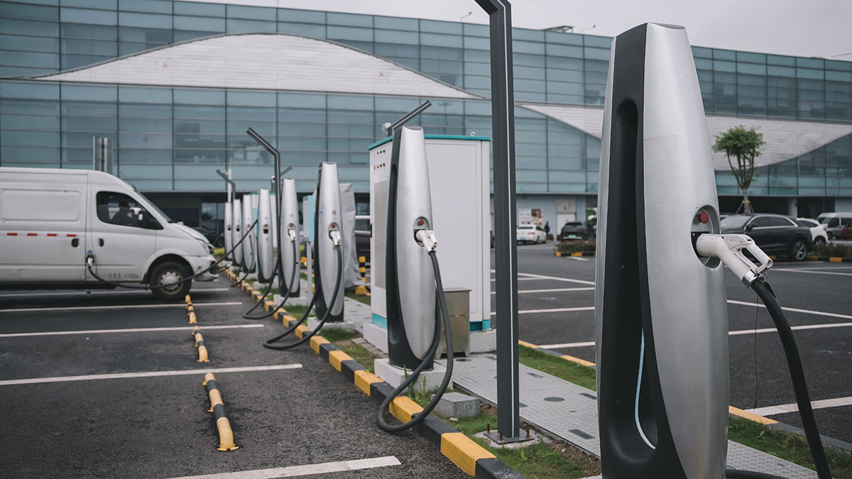
Item (vi) is new for the 2012 CE Code and requires that any electric vehicle charging equipment loads also be added to the basic load at 100% of equipment ratings.
The final step in Item (vii) is to add any additional loads at 25% of the rating of each load with a rating in excess of 1500 W if an electric range has been provided for, or 100% of the rating of each load with a rating in excess of 1500 W up to a total of 6000 W plus 25% of the load in excess of 6000 W if an electric range has not been provided for.

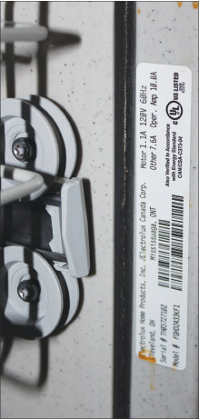
Photo 3. The nameplate of a 1500 W microwave oven

Photo 4. A 1500 W microwave oven used in the article example
As an example we will look at a 269 m² (2900 square foot) residence with the following loads:
- lighting load
- 4 small appliance branch circuits
- laundry circuit 1500 W
- natural gas heating
- air conditioner 6000 VA
- electric range 11,000 W
- hot tub 8000 W (2 hp motor)
- Level II electric vehicle charger 7200 W
- electric dryer 5000 W
- garbage disposal 800 W
- microwave 1500 W
- dishwasher 1200 W
- electric water heater 4500 W
Example Calculation:
The calculated load for the 2900 ft² (269 m²) single dwelling in this example is 173.1 amps.
The basic load is calculated based on the floor area of the single dwelling. The load for the first 90 m² is 5000 W, leaving 179 m² of floor area. The next 90 m² has a load of 1000 W, and an additional 1000 W for the remaining 89 m². The total basic load of 7000 W includes the lighting, convenience receptacles, small appliance branch circuits, laundry circuit, garbage disposal, and the dishwasher.
The heating of the single dwelling is a gas furnace and no electric heat is installed, leaving the 6000 W air-conditioning load added with a demand factor of 100%.
The electric range for this single dwelling is less than 12 kW providing a load for the calculation of 6000 W.
The 8000 W hot tub and the 7200 W electric vehicle charging equipment are now added with a demand factor of 100%.
Any additional loads with a rating in excess of 1500 W are now added with a demand factor of 25%. In this example, the additional loads over 1500 W are the 5000 W dryer and the 4500 W storage type water heater; 25% of the 9500 W gives us 2375 W to be added to the calculation.

Table 1. Summary of the single dwelling service load calculation
Now that we know the calculated load, we can determine the minimum service and conductor size. The ampacity of the load is 173.1 amps (41550 / 240 = 173.1). In most installations, the continuous load on a service is limited to the continuous load rating of the equipment being used. Subrule (3) of Rule 8-104 considers all loads continuous unless it can be shown that in normal operation the load will not persist for a total of more than one hour in any two-hour period for loads not exceeding 225 amp, or a total of more than three hours in any six-hour period for loads in excess of 225 amp. In the case of single dwelling units Subrule (2) of Rule 8-200 allows these loads to be considered as a non-continuous load for application of Rule 8-104. However, although Section 86 considers the EV charging equipment to be a continuous load, when this load is calculated for the purpose of defining the ampacity of a service in a single dwelling, such EV charging equipment load is not considered as continuous load, similarly to all other loads under this Rule. This means 100% of the calculated load for a single dwelling can be used to determine the service equipment ampere rating. For our 269 m² example a standard rating of 175 amp overcurrent device could be selected in the service box as the calculated load is 173.1 amp. Typically 175 amp rating of the overcurrent device will necessitate installation of the 200 A rated service box, as 175 A rating for the service fused disconnect or the service circuit breaker for residential installations is not available. In most cases a 200-amp service would be installed with a 175-A or 200-A trip setting or rating. Let’s consider that the trip setting of the service overcurrent device was selected at 200 A.
The size of the service conductors are now established using Rules 4-004, 4-006, and 14-104. As all distribution equipment presently available has a temperature limitation of 75⁰C, Rule 4-006 requires the allowable ampacity to be based on the 75⁰C column of either Table 2 or 4 for conductors installed in a raceway. The smallest 75⁰C conductor allowable ampacity from Tables 2 and 4 for the calculated load of 173.1 amp are 2/0 copper with an allowable ampacity of 175 amp, or 4/0 aluminum with an allowable ampacity of 180 amp.

Photo 5. The nameplate for a 1200 W dishwasher used in the article example
The next step is to verify the conductor selected meets the requirements of Rule 14-104. Rule 14-104 requires the overcurrent device to have a setting not higher than the allowable ampacity of the conductors being protected. Where the conductor allowable ampacity does not correspond with the overcurrent protection commercially available, Table 13 provides details on acceptable limits for over protection settings. Based on the fact that a 200-amp service will be installed with a main 200-amp trip setting for the breaker, Table 13 limits the conductor allowable ampacity to be not less than 176 amps. In the case of the copper conductors, the 2/0 copper conductor with the allowable ampacity of 175 amp is undersized. At this point some code users will try to apply “the 5% rule” in Subrule (1) of Rule 8-106 to the 175 allowable ampacity of Table 2. Subrule (1) of Rule 8-106 allows loads calculated in accordance with Section 8 to be within 5% of the allowable ampacity of the conductors selected. This means the 5% allowance can be applied to a calculated load. Applying the “5% rule to a conductor allowable ampacity table is a misapplication of Subrule (1).
In summary, the minimum conductor size allowed for the 200-amp service where the conductors are installed in a raceway for the example in this article is either 3/0 copper or 4/0 aluminum. If the main breaker of this service was reduced to 175 amp the minimum copper conductor size could be reduced either 2/0, and the aluminum conductor would remain at 4/0.


Find Us on Socials