This is the first of a series of articles detailing significant changes for the 2021 Canadian Electrical Code Part I (CE Code). A full copy of the CE Code is available at https://www.csagroup.org/store/.
The 2021 CE Code has 48 new or revised special terminology and definitions changes, 302 rule changes, 18 table changes, and 187 Appendix B note changes.
It has Code wide changes, including continued work on the replacement of the phrase “specifically approved for the purpose” throughout the code with changes in Sections 32, 38, 44, 54, 56, 62, 66, 68, and 70.
The 2018 CE Code new definitions for the words “cable,” “conductor,” “bare conductor,” “covered conductor,” “insulated conductor,” “jacket,” and “wire” resulted in proposals submitted to confirm that the use of the words “conductor,” “cable,” “jacket,” and “wire” is consistent throughout the code. In addition to changes in the 2018 CE Code, proposals for Sections 0, 16, 20, 32, 38, 40, 44, 54, 56, 58, 62, 66, 68, 70, 74, and 78 have been completed resulting in editorial changes for the 2021 CE Code. Proposals for the remaining Sections 52, 60, 76, and 80 will be addressed in the next cycle.
Section 0 – definition changes
The first definition change is the revised wording of the definition of “ampacity” that reads:
Ampacity — the maximum current, in amperes, that a conductor can carry continuously under the conditions of use without exceeding its temperature rating or, for insulated conductors, the insulation temperature rating. This revised definition clarifies the limitations of ampacity and is the first step for future proposals to get better consistency on the use of the word “ampacity”.
Two new definitions for “armour” and “sheath” have been added to align with product standards that reads:
Armour — a metallic covering wrapped over one or more insulated conductors that is intended primarily for physical protection against severe installation conditions but is not intended to provide a hermetic seal.
Sheath — a continuous covering that is applied over one or more insulated conductors and is intended primarily to provide a hermetic seal and, to a lesser extent, physical protection.
Editorial changes for the existing definition of “cable” will make the definition easier to understand without changing the intent.
The definition of “cable tray” has replaced the word “raceway” with the wording “supporting means.” At the same time, “cable tray” was removed from the definition for “raceway.” The Table 19 Task Force submitted these changes as part of a rewrite of Table 19 that will be discussed in a future IAEI News article.
The definition of “cablebus” added the words “cable or both” to recognise that cablebus can be manufactured with insulated conductors and cables. This change also aligns with the ANSI/CAN CSA Standard C22.2, No. 273 – Cablebus.
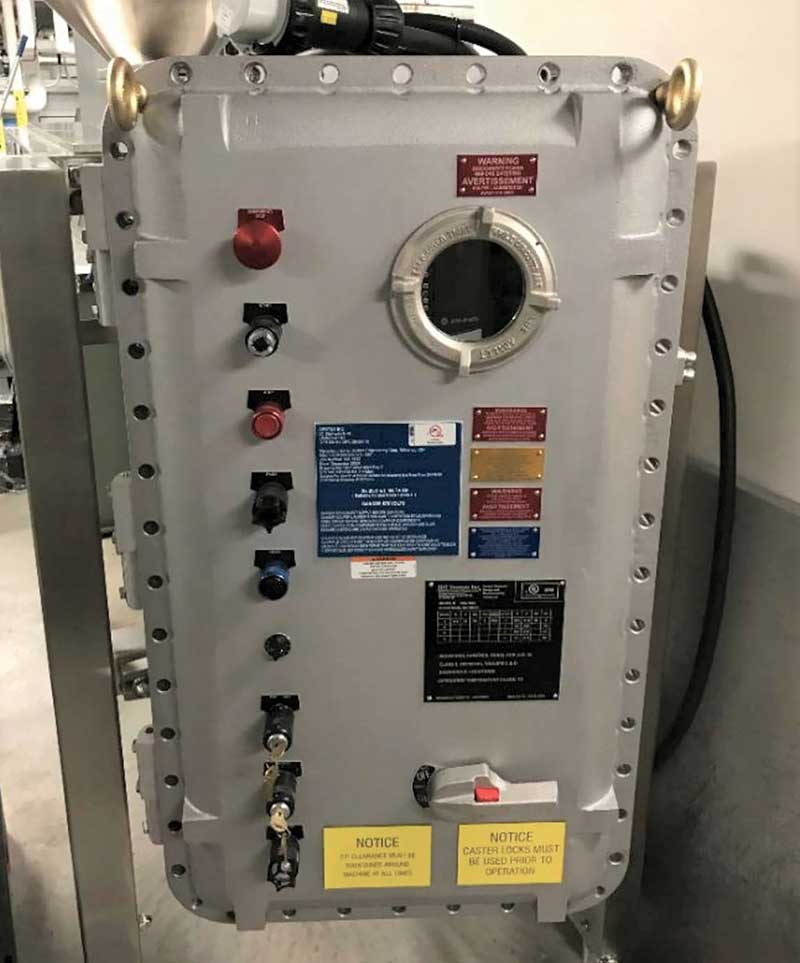
The definition for Explosion-proof enclosure was revised to harmonizes with the new edition of CSA Standard C22.2, No. 30 – Explosion-Proof Enclosures for Use in Class I Hazardous Locations to read:
Explosion-proof enclosure — an enclosure constructed so that it will:
a) withstand the pressure developed during an internal explosion of an explosive gas atmosphere;
b) prevent the transmission of an internal explosion to an explosive gas atmosphere surrounding the enclosure; and
c) not have external surface temperatures that are capable of igniting an explosive gas atmosphere surrounding the enclosure.
As part of a Climate Adaptation Project, the Task Group on Flood and Drought submitted multiple CE Code proposals, including definitions “flood elevation” and “flood hazard zone” to read:
Flood elevation – elevation of surface water resulting from a flood event designated in accordance with the National Building Code of Canada or applicable local legislation (see Appendix B).
Flood hazard zone – a spatially delineated area designated in accordance with the National Building Code of Canada or applicable local legislation as being subjected to a flood hazard (see Appendix B).
These definitions are needed to apply new rules added to the 2021 CE Code intended to address the possible effects of climate change.
The voltage definition changes align with product standards voltage ratings, and these changes now provide clear direction for dc voltages to read:
Voltage –
Extra-low voltage —
a) for ac circuits, any voltage not exceeding 30 V ac; or
b) for dc circuits, any voltage not exceeding 42.4 V dc.
Low voltage —
a) for ac circuits, any voltage exceeding 30 V ac but not exceeding 1000 V ac; or
b) for dc circuits, any voltage exceeding 42.4 V dc but not exceeding 1060 V dc.
High voltage —
a) for ac circuits, any voltage exceeding 1000 V ac; or
b) for dc circuits, any voltage exceeding 1060 V dc.
Section 2
Rule 2-032 Damage and interference has a new Subrule 3) proposed by Task Group on Flood and Drought requiring equipment that has been exposed to water to be evaluated prior to being energized, ensuring that the equipment has not been damaged. The new Appendix B note for this subrule helps explain the intent and provides details on where to get more information, like NEMA publication GD 1, Evaluating Water-Damaged Electrical Equipment.
Newly inserted Rule 2-134 Seismic restraint requirements for electrical equipment requires electrical equipment be provided with seismic restraint in compliance with the National Building Code of Canada, where it is mandated by local legislation.
2018 CE Code Rule 2-134 Sunlight resistance requirements has been renumbered to Rule 2-136 and now has a new Subrule 2) that reads:
2) Where the outer covering of a cable assembly marked sunlight resistant has been removed for termination of the cable, and the inner jacket or insulation of the internal conductors is exposed to direct rays of the sun, the internal insulated conductors shall be
a) marked as sunlight resistant; or
b) protected by tubing, tape, or equivalent that is marked as sunlight resistant.
An addition to the Appendix B note also provides the CSA Standards used to certify sunlight resistant tubing and tape.
Newly inserted Rule 2-318 Receptacles required for mobile industrial or commercial structures is a direct result of a fatality. The new rule reads:
Where a mobile industrial or commercial structure contains transfer equipment for connection of an alternate power supply, at least one receptacle of CSA configuration 5-15R or 5-20R shall be provided that is supplied by a circuit connected to or capable of being connected to the alternate power supply through the transfer equipment.
In addition, proposals have been submitted to change transfer panel requirements to make it much harder to defeat the mechanical interlocking.
Section 4
Rule 4-004 Ampacity of wires and cables has seen two changes. First Subrule 7) has a new Item a) ii), that reads:
The correction factors specified in this Rule
a) shall not apply to conductors installed
i) in auxiliary gutters containing 30 conductors or less; or
ii) inside electrical equipment for termination of these conductors at the electrical equipment;
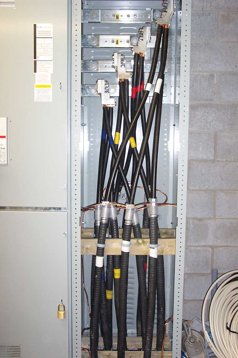
This is a significant change when applying Rule 4-006. For example, where the insulated conductor is at least 1.2 m long terminating within a distribution panel, the Rule 4-004 correction factors will not apply for conductor ampacity in conjunction with the application of Rule 4-006.
The second change for Rule 4-004 resulted in the deletion of Subrule 22 and Table 39 Minimum permitted size for 3-wire 120/240 V and 120/208 V service conductors for single dwellings and feeder conductors or cables supplying single dwelling units of row housing, apartment, or similar buildings and terminating on equipment having a conductor termination temperature of not less than 75°C, as this table with the very long name, which was introduced in the 2018 CE Code. The proposal submitted to delete this table and subrule identified code inconsistency and confusion among Code users.
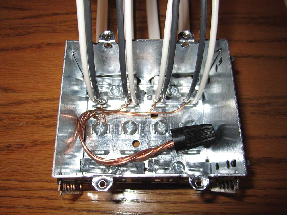
The final change for Section 4 is in Rule 4-024 Identification of insulated neutral conductors up to and including No. 2 AWG copper or aluminum, and Rule 4-032 Identification of insulated conductors. In both of these rules, the allowance to use grey insulated conductors as an identified (neutral) conductor has been deleted. This proposal’s rationale included some history of why grey insulation was originally allowed, indicating that in the 1930s, manufacturing of white conductor insulation was difficult as most “white” insulation was grey. For many years now, the ability to manufacture white insulation is much easier, and the need for grey conductor insulation as a substitute for white is no longer needed.
terminating within a distribution panel.
Section 6
The first change in Section 6 is in Rule 6-206 Consumer’s service equipment location. Subrule 1) has a new Item 1) vi) that requires service boxes and consumer’s service equipment located above the flood elevation. This means the electrical contractor will need to confirm the building is not in a flood hazard zone before installing the consumer’s service equipment in a basement.
Rule 6-212 Wiring space in enclosures, has a new Subrule 3). An Appendix B note recognizing conductors used for the connection to components like a shunt trip coil or a trip alarm (and that are integral to the function of a circuit breaker or externally operated switch) are permitted to be installed in the service box. This change is a good example of a proposal created by the Subcommittee chair as a result of an interpretation question that identified confusion in the code.
The final change in Section 6 provided clarification for both Rules 6-300 and 6-310. The title of Rule 6-310 was changed to 6-310 Use of joints and splices in consumer’s service conductors. This rule has added a reference to splices and removed the old reference to neutral conductors making the rule applicable to all consumer’s service conductors. This rule was also split into Items a) and b), including the addition of the allowance for termination of oversized conductors due to voltage drop. The same proposal also deleted Item b) ii) of Subrule 1) and Subrule 2) in Rule 6-300 Installation of underground consumer’s service conductors, dealing with joints and splices in underground consumer’s service conductors as a duplication of revised wording in Rule 6-310.
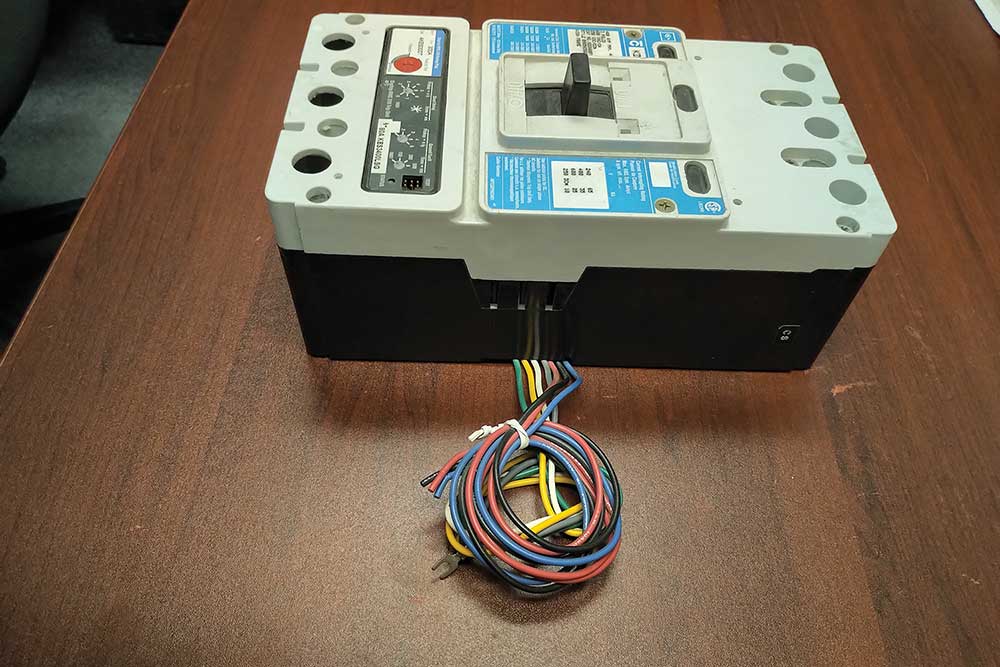
that is integral to the function of a circuit breaker.
Section 8
The first change in Section 8 is editorial changes to Rule 8-106 Use of demand factors that result from an interpretation question.
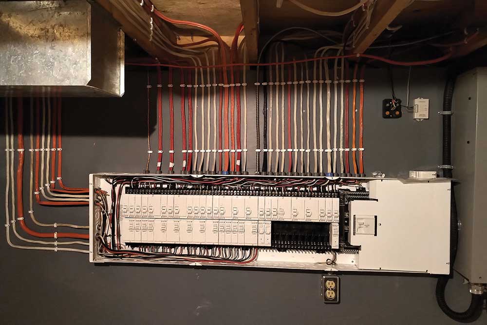
Rule 8-108 Number of spaces for branch circuit overcurrent devices has been completely revised to read:
1) Panelboards installed in single dwellings shall, at the time of the original installation, have at least four additional spaces left for future overcurrent devices with provision for a two-pole device.
2) Panelboards installed in each dwelling unit in an apartment or similar building shall, at the time of the original installation, have at least two additional spaces left for future overcurrent devices with provision for a two-pole device.
The previous rule was added to the code when residential distribution were mostly fuses. The new rule provides clear direction on the number of spaces required for future installations while recognizing current installation practices.
The final Section 8 change in Rule 8-304 Maximum number of outlets per circuit is one of the more significant code changes that may change current wiring practices in Canada. Subrule 4) covering fixed multi-outlet assemblies has not changed, but the revised Subrules 1) to 3) now reads:
1) Except as permitted by other Rules of this Code, the maximum number of outlets on any 2-wire branch circuit shall not exceed the following:
a) 12 outlets for a 15 A branch circuit where the fused switch or circuit breaker is marked for continuous operation at 80%;
b) 15 outlets for a 15 A branch circuit where the fused switch or circuit breaker is marked for continuous operation at 100%;
c) 16 outlets for a 20 A branch circuit where the fused switch or circuit breaker is marked for continuous operation at 80%; and
d) 20 outlets for a 20 A branch circuit where the fused switch or circuit breaker is marked for continuous operation at 100%.
2) Except as permitted by Subrule 3), when a receptacle is used as an outlet for the application of Subrule 1), it shall be considered as
a) 1 outlet per duplex receptacle;
b) 5 outlets per triplex receptacle; and
c) 2 outlets per quadruplex receptacle.
3) Where the connected load is known, the number of outlets shall be permitted to exceed the maximum number permitted in Subrule 1), provided that the load current does not exceed the continuous operation marking on the overcurrent device protecting the circuit.
4) …
The rule now recognizes an increased number of outlets for 20 A branch circuits with branch circuit overcurrent devices marked for continuous operation at 100%. In addition, Subrule 2) has removed the 1 A per outlet consideration and now provides clear direction when triplex and quadruplex receptacles are installed.
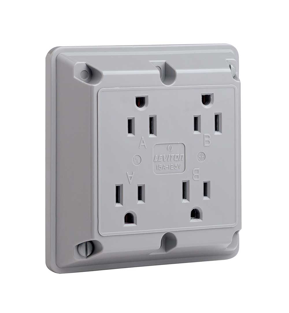
considered two outlets. Courtesy of Leviton Canada.
Section 10
The first change is Section 10 is in Rule 10-302 Use for impedance grounding systems. The rule was reduced from four to three subrules by moving the monitoring and alarm to an easier readable Table 17.
Newly inserted Rule 10-612 Installation of bonding conductors is a new rule bringing requirements from the 2015 CE Code that were missed during the original rewrite for Section 10 for the 2018 CE Code. This new rule reads:
1) The bonding conductor shall be permitted to be spliced or tapped.
2) Where more than one bonding conductor enters a box, all such conductors shall be in electrical contact with each other by one of the following means:
a) securing all bonding conductors under bonding screws; or
b) connecting all bonding conductors together with a solderless connector, and then connecting a minimum of one conductor, not smaller than the largest bonding conductor, to the box by a bonding screw or a bonding device.
3) Where a bonding conductor is run in the same raceway with other conductors of the circuit to which it is connected, it shall be insulated, except that an uninsulated bonding conductor shall be permitted to be used where the length of the raceway does not exceed 15 m and does not contain more than the equivalent of two quarter bends.
4) Where circuit conductors are installed in a raceway, a separate bonding conductor, when required, shall be installed in the same raceway as the circuit conductors.
5) Where a separate bonding conductor is run with single-conductor cables, it shall follow the same route as the cables.
6) A copper bonding conductor shall
a) if No. 6 AWG or larger and attached securely to the surface on which it is carried, be protected where exposed to mechanical damage; and
b) if smaller than No. 6 AWG, or if the installation does not come within the provisions of Item a), be installed and protected in the same manner as the circuit conductor for a given installation.
7) An aluminum bonding conductor shall
a) if No. 4 AWG or larger and attached securely to the surface on which it is carried, be protected where exposed to mechanical damage; or
b) if smaller than No. 4 AWG, or if the installation does not come within the provisions of Item a), be installed and protected in the same manner as the circuit conductor for a given installation.
Rule 10-614 has been renumbered Rule 10-616 Size of system bonding jumper or bonding conductor. The change for this rule is in the addition of the words “the ampere rating or setting of” at the beginning of Item a) of Subrule 3) to read:
3) The size of a field-installed bonding conductor installed at other than service equipment shall not be less than that determined in accordance with Table 16 based on
a) the ampere rating or setting of the overcurrent device protecting the ungrounded conductors; or
b) the allowable ampacity of the largest ungrounded conductor for installations where the size of the circuit conductors is increased to compensate for voltage drop.
Subrule 2) Item b).
Item a) change clarifies that the ampere rating or setting of the overcurrent device is to be used to determine the size of the bonding conductor when applying Table 16.
The final change in Section 10 is the deletion of Item f) in Rule 10-700. Item f) provided direction for the equipotential bonding of non-electrical equipment related to passenger ropeways, which was deleted as a duplication of recently added requirements in Section 58.
The next article will continue with Section 12, including the deletion of knob and tube rules, a new method to determine conduit fill, and the new Table 19.