
Exactly three years ago, I authored an article on this subject. Since that time, I am still receiving feedback and questions from the readers. This article provides answers to the follow-up questions on the referenced subject.
Question 1
Is it mandatory to comply with spacing arrangements depicted in diagrams of the informative Appendix D of the Canadian Electrical Code, Part I (CE Code)?
Answer to question 1: Note on “Appendix D- Tabulated general information” states the following: “Note: This Appendix is an informative (non-mandatory) part of this Code.”
This means that, in general, Appendix D is used as an informative document. However, when a CE Code user decides to apply Tables D8 – D11 for selection of ampacity of conductors in an underground run, the CE Code user must apply appropriate D8 – D11 series tables only when the user decides to utilize these tables in conjunction with one of the configurations shown in the respective Diagrams D8 to D11.
Subrules 4-004(1)(d) and 4-004(2)(d) of the CE Code mandate such compliance (see below):
“4-004 Ampacity of wires and cables (see Appendix B)
1) The maximum current that a copper conductor of a given size and insulation is permitted to carry shall be as follows:…
d) single-conductor and 2-, 3-, and 4-conductor cables and single-conductor and 2-, 3-, and 4-conductor metal-armoured and metal-sheathed cables, unshielded and rated not more than 5 kV, in conductor sizes No. 1/0 AWG and larger, installed in accordance with configurations described in Diagrams D8 to D11 in an underground run, directly buried or in a raceway, as specified in Tables D8A to D11B or as calculated by the IEEE 835 calculation method…”
Therefore, if the CE Code user wants to apply installation arrangements depicted in one of the D8- D11 series diagrams, with exact spacings shown in the respective diagram, the Code user must select conductors or cables in accordance with the ampacity value from a D8 – D11 series table.
If a necessary configuration of conductors or cables does not exist in Appendix D of the CE Code, then the Code user must follow the calculation method described in IEEE 835.
Question 2
Why does each D8 – D11 series table provide ampacities only for 90 Deg. C-rated conductors and cables?
Answer to question 2: Usually, all insulated cables and conductors are designed and constructed with insulation rated for 90 Deg. C and ampacity values for insulated conductors and cables are based on insulation temperature rating.
As selected cables and conductors are eventually terminated on equipment that may have limitations for a maximum conductor termination temperature, then requirements of Rule 4-006 of the CE Code may have to be applied for such conductors and cables to the first 1.2 m of conductor length measured from the point of termination on the equipment. Each of the D8 – D11 or D17 series tables are provided with notes recognizing this fact and advising the Code users accordingly (see below):
“Notes:
2) Underground ampacities for an insulated conductor or cable temperature of 75 °C may be obtained by multiplying the appropriate ampacity at 90 °C conductor insulation temperature by the derating factor 0.886.
3) See Rule 4-006 for equipment termination temperature requirements.”
Therefore, if the underground conductors or cables are terminated on the equipment located on the ground, then such ampacity of the underground conductors or cables must be multiplied by the derating factor 0.866, in accordance with note 2 to underground ampacity tables as shown above.
If, however, there is a need to evaluate ampacity values of selected underground conductors or cables with corresponding ampacity values in Tables 1 – 4, where such conductors run above the ground and where such above-ground conductors or cables would have to be terminated on the equipment in accordance with Rule 4-004(6), then provisions of Subrule 4-004(16) below would have to be met, and the ampacity values in Tables 1 – 4 would have be selected based on 75 Deg. C column.
“Subrule 4-004(16) Where more than one ampacity could apply for a given circuit of single-conductor or multi conductor cables as a consequence of a transition from an underground portion to a portion above ground, the lower value shall apply except as permitted in Subrule 17).”
Question 3
Under what condition does Subrule 4-004(16) of the CE Code must apply?
Answer to question 3: If after transitioning from underground run to above-ground installation, conductors or cables are installed above the ground in accordance with provisions of the CE Code for more than 3 m or for more than 10% of the entire circuit, including underground and above ground portion, (whichever condition is less), Rule 4-004(16), shown in answer to question 2 above, must apply.
It should be noted that the Technical Committee for the CE Code has approved changes to Subrule 4-004(17) as follows:
“17) Except as required by Rule 4-006, where the lower ampacity portion of a cable or conductor installation consisting of not more than four conductors per run does not exceed 10% of the circuit length or 3 m, whichever is less, the higher ampacity shall be permitted.”
These changes will be incorporated into the 2027 edition of the CE Code.
Question 4
When parallel runs of underground conductors and cables terminate on equipment located immediately on a ground pad, and the spacing between such parallel conductors or cables prescribed by the applicable D8 – D11 diagrams cannot be maintained, what correction factors for derating of conductors are required to be used by the CE Code?
Answer to question 4: Conductors and cables usually terminate inside the equipment enclosure containing a busway, a fused switch, and a circuit breaker. Such enclosure of approved equipment (equipment certified to the applicable CSA safety standard) has dimensions sufficient to accommodate parallel runs of conductors or cables for termination, and no additional correction factors should be applied inside such equipment enclosure. Subrule 4-004(7) of the CE Code reflects this fact as follows:
“Subrule 4-004(7) The correction factors specified in this Rule
a) shall not apply to conductors installed
i) in auxiliary gutters containing 30 conductors or less; or
ii) inside electrical equipment for termination of these conductors at the electrical equipment”
Busway is defined in the CE Code as follows:
“Busway — a raceway consisting of metal troughing (including elbows, tees, and crosses, in addition to straight runs) containing conductors that are supported on insulators.”
Installation of busways is governed by Rules 12-2000 – 12-2020 of the CE Code.
A typical busway is a piece of equipment that is designed, constructed, tested, marked, and certified to the CSA standard C22.2 No. 27 “Busways” if a busway is used as a part of switchgear, such busway, despite being “approved” to the standard C22.2 No. 27, becomes a component of the switchgear, and termination requirements at the busway comply with applicable provisions of the CSA standard C22.2 No. 31 “ Switchgear assemblies”. So, if the standard for switchgear indicates that the maximum termination temperature of field-installed conductors or cables at the busway is 75 Deg. C, then such conductors and cables must be selected based on ampacity values for 75 Deg. C.
Question 5
Does the CE Code have general spacing requirements for conductors installed in parallel?
Answer to question 5: Subrule 12-108 allows conductors to be installed in parallel under the following conditions:
“12-108 Conductors in parallel (see Appendix B)
1) Ungrounded and grounded circuit conductors of similar conductivity in sizes No. 1/0 AWG and larger, copper or aluminum, shall be permitted to be installed in parallel sets provided that each parallel phase or grounded conductor set individually consists of conductors that
a) are free of splices throughout the total length;
b) have the same circular mil area;
c) have the same type of insulation;
d) are terminated in the same manner;
e) are of the same conductor material; and
f) are the same length.”
Appendix B note on Rule 12-108 provides the following clarification for single conductor cables:
“Appendix B Note on Rule 12-108
The following configurations are acceptable for insulated conductors and single-conductor cables in parallel to minimize the difference in inductive reactance and the unequal division of current. Additional insulated conductors and single-conductor cables in parallel should be arranged in repetitive configurations of those illustrated. Other factors that affect load sharing and should be considered are outlined in Subrule 1).”
Figure B12-2 in Appendix B Note on spacing between single conductor cables in a parallel run offers the following configurations:
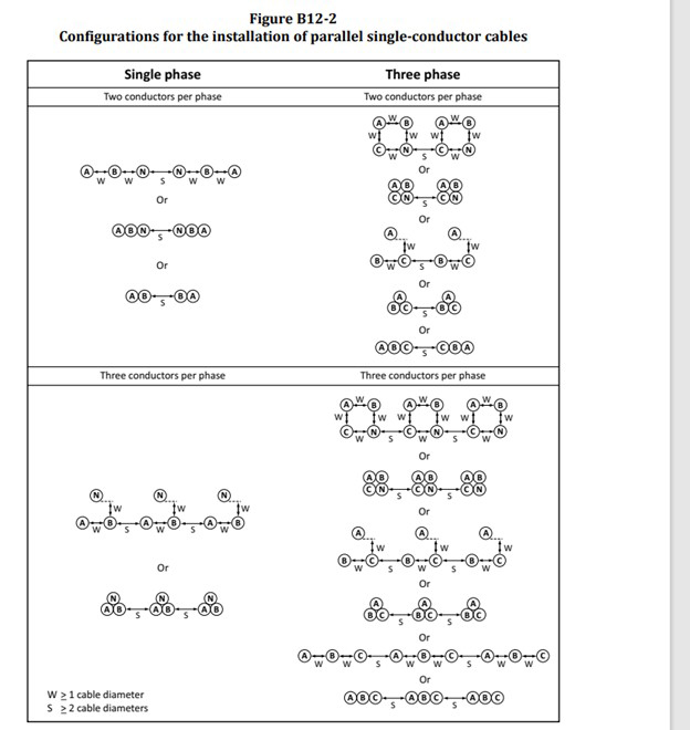
It should be noted that such spacing restrictions do not apply to multi-conductor cables installed in parallel or to parallel sets of conductors installed in raceways.
Question 6
Does the CE Code regulate spacing requirements between multi-conductor cables or between conductors in raceways installed above the ground?
Answer to question 6: Subrule 4-004(13) recognizes that multi-conductor cables could run in contact with each other. If such contact exceeds distances greater than 600 mm, then applicable correction factors listed in Table 5C must apply based on the total number of conductors in the cables being in contact.
“4-004(13) Where multi-conductor cables are run in contact for distances greater than 600 mm, the ampacity of the conductors shall be corrected by applying the correction factors from Table 5C based on the total number of conductors in the cables“
For conductors installed in raceways, such restrictions do not exist in the CE Code.
It should be noted that general provisions of Rule 4-004 for the use of correction factors in accordance with Table 5C when conductors are installed in a raceway, apply only if one raceway contains more than 3 phase conductors and one neutral conductor of the circuit.(see Subrule 4-004(3) below):
“4-004(3) A neutral conductor that carries only the unbalanced current from other conductors, as in the case of normally balanced circuits of three or more conductors, shall not be counted in determining ampacities as provided for in Subrules 1) and 2).”
Hopefully, answers to the posted questions provide additional clarification on the referenced subject.
As usual, local AHJ, enforcing provisions of the legally adopted CE Code, should always be contacted regarding any issues related to all applicable conditions of a specific installation.