It is very gratifying and encouraging to receive a wide range of questions and comments about my articles published in this journal and additional questions on new subjects.
A few of such additional questions received recently were related to the loading and overloading of distribution transformers in industrial, institutional, commercial, and residential applications.
As such, this article is dedicated to the subject of loading and overloading of distribution transformers from the perspective of the Canadian Electrical Code, Part I (CE Code).
It should be noted that transformer manufacturers may have different loading and overloading criteria for distribution transformers – from the perspective of their design, construction, testing, certification, and conditions of use.
From the point of view of the electrical application, a transformer is an electrical equipment that transfers electric energy from one alternating-current circuit to one or more other circuits, either increasing (stepping up) or reducing (stepping down) the voltage.
A typical distribution transformer is used for the transformation of electrical energy from one voltage to another at voltages less than 33KV. Transformers operating at voltages higher than 33 KV are power transformers, and they are used mostly in transmission and sometimes – in distribution systems.
As with any electrical machine, a transformer has losses. A “loss” can be defined as the difference between input power and output power. An electrical transformer is a static device. Hence mechanical losses like friction losses are absent in it. A transformer only has electrical losses (iron losses and copper losses).
Just like any other electrical machine, the efficiency of a transformer can be defined as the output power divided by the input power. (Efficiency = output/input).
Typically, transformers are efficient electrical devices. Most of the high-efficiency transformers have full load efficiency between 95% to 98.5%.
From the perspective of the CE Code, transformers are installed in feeders and branch circuits – to transform the supply voltage to the distribution voltage and to transform the distribution voltage to the utilization voltage.
When a transformer is installed upstream of the service entrance equipment (upstream of the services box), such transformer is installed as a part of the power supply authority/utility infrastructure, and installation of utility transformers (and other equipment owned by the utility) is exempt from the scope of the CE Code.
As such, the following definitions of the CE Code could be helpful for the purpose of this subject:
“Branch circuit — that portion of the wiring installation between the final overcurrent device protecting the circuit and the outlet(s)
Feeder — any portion of an electrical circuit between the service box or other source of supply and the branch circuit overcurrent devices.
Service, consumer’s — all that portion of the consumer’s installation from the service box or its equivalent up to and including the point at which connection is made to the supply service.
Service, supply — any one set of conductors run by a supply authority from its mains to a consumer’s service.”
So, if a transformer is installed in a feeder or in a branch circuit, it becomes a part for such feeder or branch circuit, and the rating of the transformer must be consistent with the rating of that feeder or branch circuit.
Considering this observation, the following provisions of Rule 8-104 would be relevant to this subject:
“8-104 Maximum circuit loading
1) The ampere rating of a consumer’s service, feeder, or branch circuit shall be the ampere rating of the overcurrent device protecting the circuit or the ampacity of the conductors, whichever is less.
2) The calculated load in a circuit shall not exceed the ampere rating of the circuit.”
If the rating of the circuit is “the ampere rating of the overcurrent device protecting the circuit or the ampacity of the conductors,” and the transformer is a part of the circuit, it is appropriate to visit Rules of Section 26 of the CE Code, which provide requirements for overcurrent protection of HV transformers, of dry type LV transformers and for ampacity of conductors connected to the primary and secondary sides of the transformers (see below):
“26-250 Overcurrent protection for power and distribution transformer circuits rated over 750 V
1) Except as permitted in Subrules 2), 3), and 4), each ungrounded conductor of the transformer feeder or branch circuit supplying the transformer shall be provided with overcurrent protection
a) rated at not more than 150% of the rated primary current of the transformer in the case of fuses; and
b) rated or set at not more than 300% of the rated primary current of the transformer in the case of breakers.
2) Where 150% of the rated primary current of the transformer does not correspond to a standard rating of a fuse, the next higher standard rating shall be permitted.
3) An individual overcurrent device shall not be required where the feeder or branch circuit overcurrent device provides the protection specified in this Rule.
4) A transformer having an overcurrent device on the secondary side rated or set at not more than the values in Table 50 or a transformer equipped with coordinated thermal overload protection by the manufacturer shall not be required to have an individual overcurrent device on the primary side, provided that the primary feeder overcurrent device is rated or set at not more than the values in Table 50.
26-254 Overcurrent protection for dry-type transformer circuits rated 750 V or less
1) Except as permitted in Subrule 2), each ungrounded conductor of the transformer feeder or branch circuit supplying the transformer shall be provided with overcurrent protection rated or set at not more than 125% of the rated primary current of the transformer, and this primary overcurrent device shall be considered as protecting secondary conductors rated at 125% or more of the rated secondary current.
2) Notwithstanding Subrule 1), a transformer having an overcurrent device on the secondary side set at not more than 125% of the rated secondary current of the transformer shall not be required to have an individual overcurrent device on the primary side, provided that the primary feeder overcurrent device is set at not more than 300% of the rated primary current of the transformer.
3) Where a value not exceeding 125% of the rated primary current of the transformer as specified in Subrule 1) does not correspond to the standard rating of the overcurrent device, the next higher standard rating shall be permitted.
26-256 Conductor size for transformers
1) The conductors supplying transformers shall have an ampacity rating
a) not less than 125% of the rated primary current of the transformer for a single transformer; or
b) not less than the sum of the rated primary currents of all transformers plus 25% of the rated primary current of the largest transformer for a group of transformers operated in parallel or on a common feeder.
2) The secondary conductors connected to transformers shall have an ampacity rating
a) not less than 125% of the rated secondary current of the transformer for a single transformer;
or
b) not less than 125% of the sum of the rated secondary currents of all the transformers operated in parallel
3) Notwithstanding Subrules 1) and 2), primary and secondary conductors shall be permitted to have an ampacity rating not less than that required by the demand load, provided that they are protected in accordance with Rules 14-100 and 14-104.
4) Where the transformer overcurrent protection is more than 125% of the rated primary or secondary current in accordance with Rule 26-250 1) or 2) or 26-254 3), the primary and secondary conductors connected to the transformer shall be protected in accordance with Rules 14-100 and 14-104.
5) Where multi-rating transformers are used, the primary and secondary conductors shall have an ampacity rating not less than 125% of the rated primary and secondary current of the transformer at the utilization voltage.”
So, based on the above-stated Rules in Section 26 of the CE Code, the load connected to a transformer secondary winding cannot exceed the ampere rating/setting of the overcurrent device installed in the transformer primary and multiplied by the ratio of the primary to the secondary voltage. And, of course, this connected load also cannot exceed the ampacity of the transformer secondary conductors.
It is also important to note that the load connected to the transformer must comply with conditions outlined in Subrule 8-104(5) or 8-104(6), where such continuous load is dependent on whether a fused switch or circuit breaker is marked for continuous operation at 100% or at 80% of the ampere rating of its overcurrent devices.
This latter fact is recognized by Rule 26-258, shown below:
“26-258 Transformer continuous load
For the purpose of transformer overcurrent protection and conductor sizes selected in accordance with Rules 26-250 to 26-256, the continuous load as determined from the calculated load connected to the transformer secondary shall not exceed the values specified in Rule 8-104 5) or 6).”
Now, we are ready to deal with specific examples of transformer loading (and overloading).
Let’s use 3 examples shown below, where primary overcurrent protective device is a circuit breaker and copper conductors based on Table 2 of the CE Code are used.
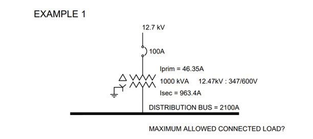
In accordance with Rule 26-250(1)(b), a 100 A rated circuit breaker is selected in the high voltage primary circuit of this 1000 KVA transformer.
Ampacity of the primary conductors would have to be based on the requirement of Rule 26-256(4), which mandates that ampacity of primary conductors must be not only 125% or more than the transformer primary current but be not less than the rating of the primary O/C device, as required by Rule 14-104 of the CE Code. As such, #3 AWG copper conductors with 100 A ampacity would be selected from Table 2 of the CE Code, based on 75 Deg. C column.
Ampacity of the transformer secondary conductors would have to be not less than the rating of the primary O/C device multiplied by voltage ratio between primary and secondary winding.
It means that the ampacity of the secondary conductors including the ampacity of the distribution bus would have to be not less than 100 A x 12.47 KV : 0.6 KV = 100 x 20.8 = 2080 A.
It means that six 500 kcmil conductors per each phase would be selected for installation in parallel for the transformer secondary based on 75 Deg. C column of Table 2 of the CE Code – with combined ampacity of 2280 A.
And what about maximum load allowed to be connected to the transformer secondary? It depends whether the 100 A circuit breaker is marked for continuous operation at 100% or at 80% of the ampere rating of its overcurrent devices. If it is marked for 100%, then the maximum allowed connected load is 2080 A. However, if the circuit breaker is marked continuous operation at 80%, then the maximum allowed connected load cannot exceed 2080 x 0.8 = 1664 A. It is interesting to note that in both these cases, the ampacity of connected load is allowed to be higher than the rated secondary current of 963.4 A. It means that if the circuit breaker is marked for continuous operation at 100%, then in accordance with Rule 8-104, the transformer can be loaded by 2080: 963.4 or by 2.16 times higher than the transformer-rated secondary current. If, however, the circuit breaker is marked for continuous operation at 80%, then in accordance with Rule 8-104, the transformer can be loaded by 1664 A: 963.4A or by 1.72 times higher than the transformer rated secondary current. Of course, the transformer manufacturer should be also consulted in this regard from the perspective of design, construction and testing of each specific type of transformer.
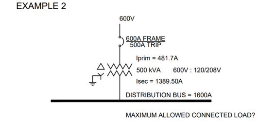
In accordance with Rule 26-254(1), a 600 A rated circuit breaker is selected with the trip setting of 500 A in the 600 V primary circuit of this 500 KVA transformer.
Ampacity of the primary conductors would have to be based on the requirement of Rule 26-256(1), which mandates that ampacity of primary conductors must be 125% or more than the transformer primary current. This Subrule is appropriate for use, as the rating of primary circuit breaker is less than 125% of the transformer primary current.
It means that two 250 kcmil conductors per each phase would be selected for installation in parallel for the transformer primary based on 75 Deg. C column of Table 2 of the CE Code – with combined ampacity of 510 A.
Ampacity of the transformer secondary conductors would have to be not less than the rating of the primary O/C device multiplied by voltage ratio between primary and secondary winding.
It means that the ampacity of the secondary conductors including the ampacity of the distribution bus would have to be not less than 500 A x 600V : 208V = 500 x 2.88 = 1440 A.
Therefore, six 250 kcmil conductors per each phase would be selected for installation in parallel for the transformer primary based on 75 Deg. C column of Table 2 of the CE Code – with combined ampacity of 1530 A.
And what about maximum load allowed to be connected to the transformer secondary? It depends whether the 600 A circuit breaker is marked for continuous operation at 100% or at 80% of the ampere rating of its overcurrent devices. If it is marked for 100%, then the maximum allowed connected load is 1440 A.
However, if the circuit breaker is marked continuous operation at 80%, then the maximum allowed connected load cannot exceed 1440 x 0.8 = 1152 A. It is interesting to note that in this example, the circuit breaker marking for continuous operation at 100% or at 80% of the ampere rating of its overcurrent devices, yields different results for maximum allowed connected load. If the circuit breaker is marked for continuous operation at 100%, then in accordance with Rule 8-104, the transformer can be loaded by 1440A : 1389.5A or only by 3.6% higher than the transformer rated secondary current. If, however, the circuit breaker is marked continuous operation at 80%, then in accordance with Rule 8-104, the transformer can be loaded by 1152A : 1389.5A or only to 83% of the transformer rated secondary current.
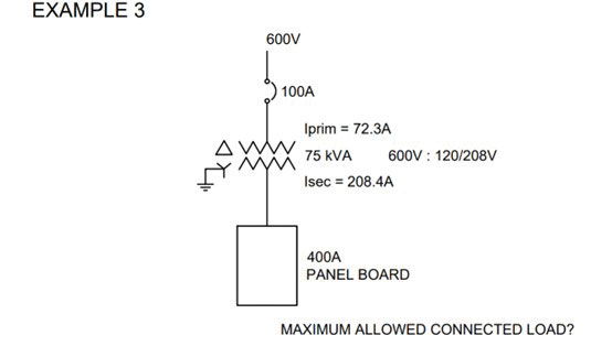
In accordance with Rule 26-254(3), a 100 A rated circuit breaker is selected in the 600 V primary circuit of this 75 KVA transformer.
Ampacity of the primary conductors would have to be based on the requirement of Rule 26-256(1), which mandates that ampacity of primary conductors must be 125% or more than the transformer primary current. This Subrule is appropriate for use, if the ampacity of selected conductor is not less than 100 A (not less than rating of the primary overcurrent device, as required by Rule 14-104). As such, #3 AWG copper conductors with 100 A ampacity would be selected from Table 2 of the CE Code, based on 75 Deg. C column.
Ampacity of the transformer secondary conductors would have to be not less than the rating of the primary O/C device multiplied by voltage ratio between primary and secondary winding.
It means that the ampacity of the secondary conductors including the ampacity of the distribution bus would have to be not less than 100 A x 600 V : 208 V = 100 x 2.88 = 288 A.
Therefore, 350 kcmil conductors would be selected for installation for the transformer secondary based on 75 Deg. C column of Table 2 of the CE Code – with ampacity of 310 A.
And what about maximum load allowed to be connected to the transformer secondary? It depends whether the 100 A circuit breaker is marked for continuous operation at 100% or at 80% of the ampere rating of its overcurrent devices. If it is marked for 100%, then the maximum allowed connected load is 288 A.
However, if the circuit breaker is marked continuous operation at 80%, then the maximum allowed connected load cannot exceed 288 x 0.8 = 230.4 A. It is interesting to note that in both these cases (similarly to example 1), ampacity of connected load is allowed to be higher than the rated secondary current of 208.4 A. It means that if the circuit breaker is marked for continuous operation at 100%, then in accordance with Rule 8-104, the transformer can be loaded by 288A : 208.4A or by 1.38 times higher than the transformer rated secondary current. If, however, the circuit breaker is marked for continuous operation at 80%, then in accordance with Rule 8-104, the transformer can be loaded by 230.4A: 208.4A or by 1.11 times higher than the transformer rated secondary current.
Hopefully, this article clarifies the questions submitted by the readers.
And as usual, local AHJ must be always consulted – to discuss specific installation issues. Transformer manufacturers also should be consulted from the perspective of specific characteristics of transformers.