Since their inception, batteries (a.k.a. energy storage systems) have been used in photovoltaic (PV) power systems. Most energy users require continuous power, and of course, PV systems do not provide power when there is no sunlight. Therefore, even the very first space and terrestrial applications using PV cells and modules were coupled with batteries to provide consistent delivery of energy to the load. And with more frequent utility outages due to various environmental events, batteries are even more important in today’s PV systems.
Historical Perspective
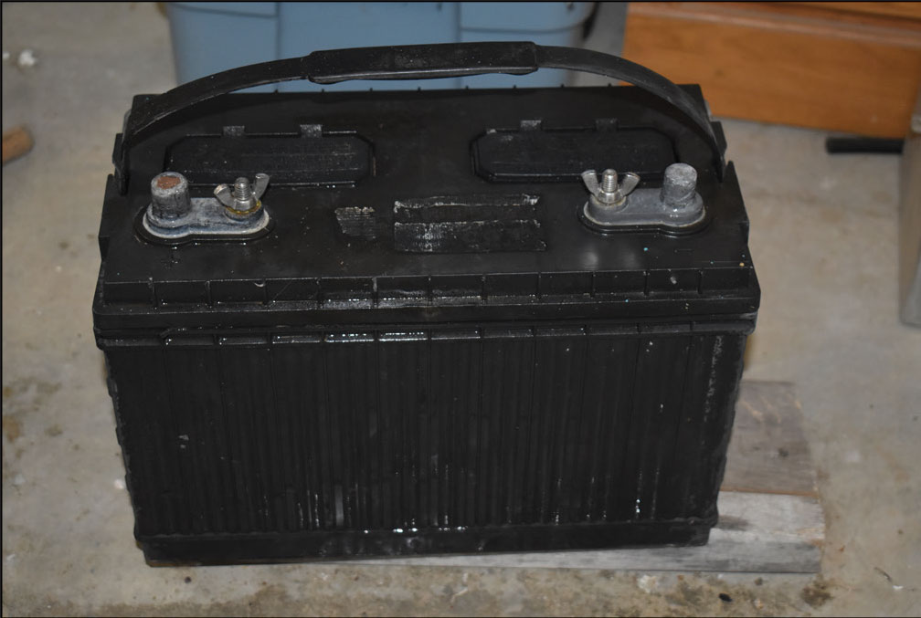
Some of the very first terrestrial uses of PV modules were for providing remote lighting in residences and for pumping water. These early (1970’s) PV modules had powers in the range of 10 to 40 W (watts) and produced electricity at about 17 volts (V) direct current (DC), which is the peak power point voltage for nominal 12-volt PV modules. These PV modules normally had 36 cells connected in series, although some had only 30 cells in series. These early applications used 12 V automotive batteries (flooded lead-acid type—see photo 1) or 12V deep-cycle marine batteries and 12 V automotive light bulbs and 12 V DC water pumps. Very early relay-type charge controllers managed the state of charge of the batteries by monitoring the battery voltage and connecting the PV system to the batteries as necessary to keep them charged but not overcharged. Relays were also used, again monitoring battery voltage, to provide a low voltage disconnect of the loads when the batteries became too deeply discharged. Those early PV modules were quite expensive and were priced in the range of $25 per watt and higher. By the mid-1980s, PV modules were selling in some markets for seven dollars per watt.
As time progressed, the PV modules with an output of 24 V (nominal) became available, and lighting and pumps kept pace, matching that voltage. The power output also increased with these 24 V modules and ranged in the 50-to-60-watt level. Solid-state charge controllers came on the market and were more efficient than the older relay-type charge controllers. Eventually, the charge controllers had peak-power-tracking functions, which allowed the controller to extract the maximum energy available from the PV module throughout the day while still maintaining the battery at an optimal state of charge.
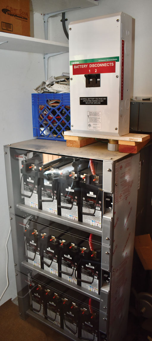
Many off-grid, remotely located PV systems now have battery systems operating at 48 V DC (see photo 2) or higher with matching PV arrays at that voltage and charge controllers and various DC loads also operating at that voltage. Currently, there are even charge controllers that can accept the output up to 600 V DC from the PV array, and while peak-power tracking that output from the array, they can provide charge control for a 48 V DC battery bank. Such a charge controller can facilitate the addition of a 48-volt battery bank to a PV system with a much higher DC array output voltage.
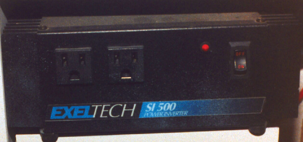
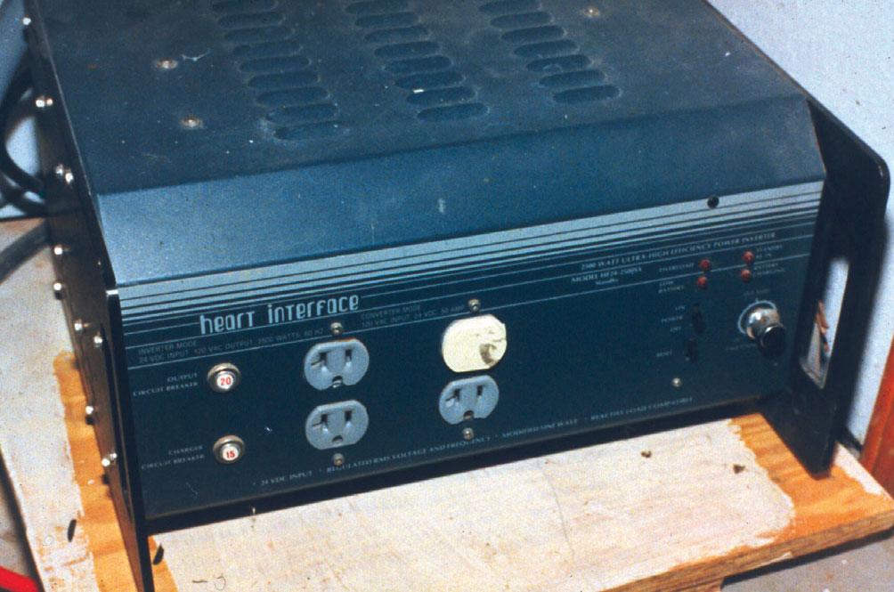
Standalone inverters became available, which could take the output of a 12 V, 24 V, or 48 V DC battery bank (depending on the inverter model) and convert it to 120 V, 60 Hz alternating current (AC). Some of these early inverters were rated at 500 W (see photo 3), 1000 W, and up to 2000 to 2500 W AC output (see photo 4). These early standalone inverters had a rectangular waveform output at 60 Hz and could not be used with all types of electronic loads. Eventually, the inverters were improved to the point where they output pure sinusoidal 60 Hz waveforms, which could be used with nearly all loads. The use of the inverters allowed most standard AC loads to be operated with the PV system in remote locations. Battery banks continued to be larger but, in many cases, still used multiple series and parallel connections off 12 and 24 V flooded lead-acid batteries. In many cases, larger industrial batteries at 12 or 24 volts were used in these remote, off-grid applications.
In parallel development efforts in the late 1970s and early 1980s, utility-interactive PV inverters were developed which could take the DC output of a PV array and feed it to local AC loads or feed the utility with AC energy if more energy than local requirements was available from the PV system. These were called “utility interactive” inverters because they could not accomplish the DC to AC conversion process without utility voltage (nominal 120 or 240 V -12% to +10%) and frequency signals (nominal 60 Hz -0.7 Hz to +0.5 Hz) present on their AC outputs. This meant that with no utility present and within these tolerances, the PV inverter would not work, and no power, either the utility or PV, would be delivered to the AC loads.
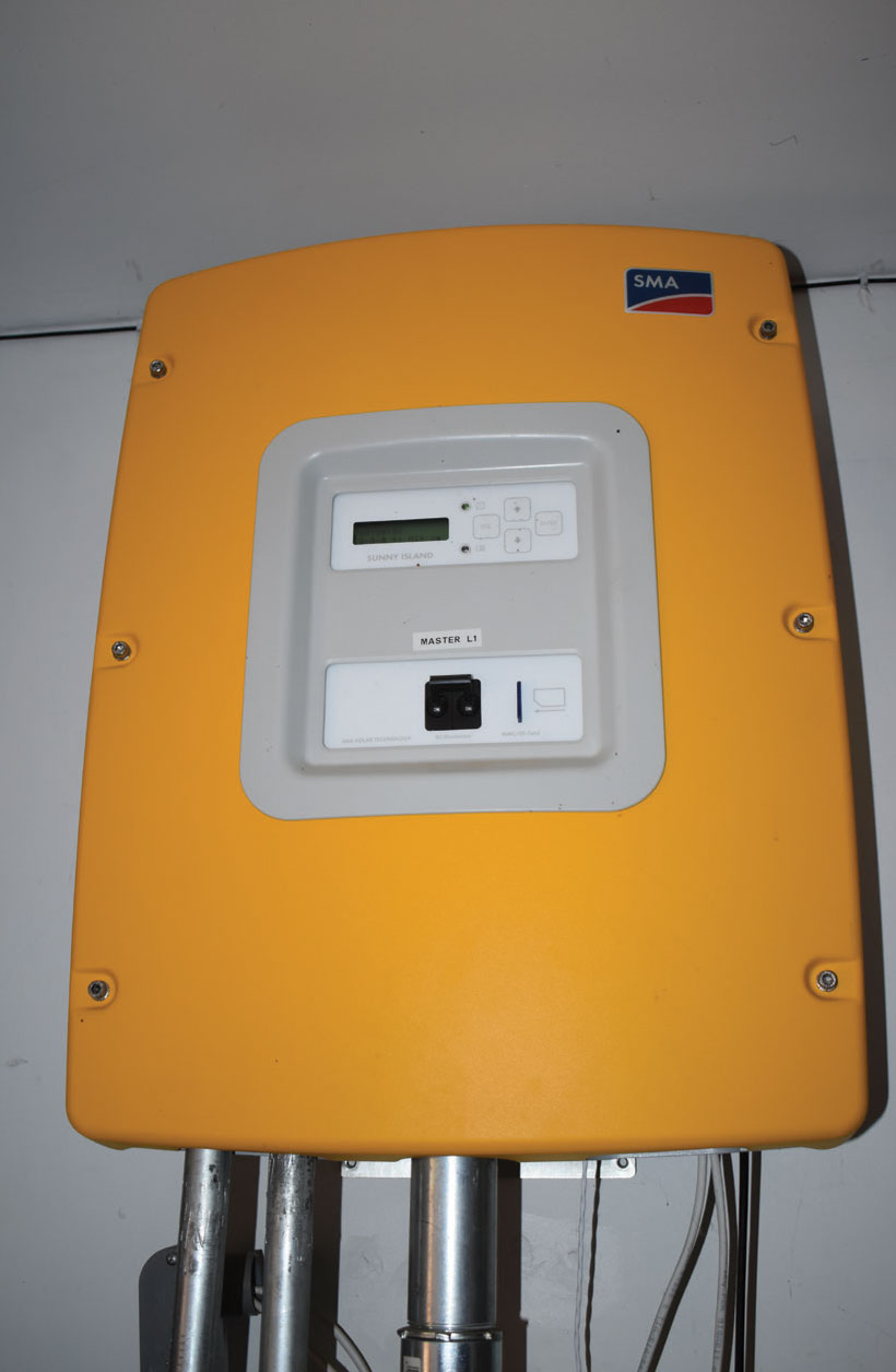
In the late 1970s and 1980s and continuing today, the features of the utility-interactive inverter were merged with the features of the standalone inverter producing a multimode inverter. The multimode inverter has an AC input/output connection to the utility and an AC output connection that would be connected to local AC loads (see photo 5). There was a connection to the battery; the battery could be charged from the utility when necessary and supplied 60 Hz, 120 V AC power to connected loads. The battery was also charged from a DC output of the PV array in daylight hours through a charge controller. This type of multimode PV system was called a DC coupled PV system.
In later inverter versions, the AC output of the multimode inverter could also accept AC inputs from the output of a second utility-interactive inverter connected to the DC PV system. This AC output from the second utility-interactive inverter could be used to power local loads and through the multimode inverter, charge the battery if necessary and feed excess PV energy to the utility. This type of multimode system was known as an AC coupled system, and there was no charge controller for DC charging the batteries from the PV array. The multimode inverter managed the battery charge and discharge process with energy from either the utility or from the PV array through the utility-interactive inverter. Since the multimode inverter could supply 60 HZ AC at 120 V or 240 V to the protected loads, it could also establish the voltage and frequency reference signals required for the operation of the utility-interactive inverter connected to the PV array.
These early types of PV systems, the standalone (off-grid system) and the utility-interactive system with and without batteries, are with us today, and many users opt for these types of systems. However, progress will not be held back; newer versions or modifications of these systems are currently very popular.
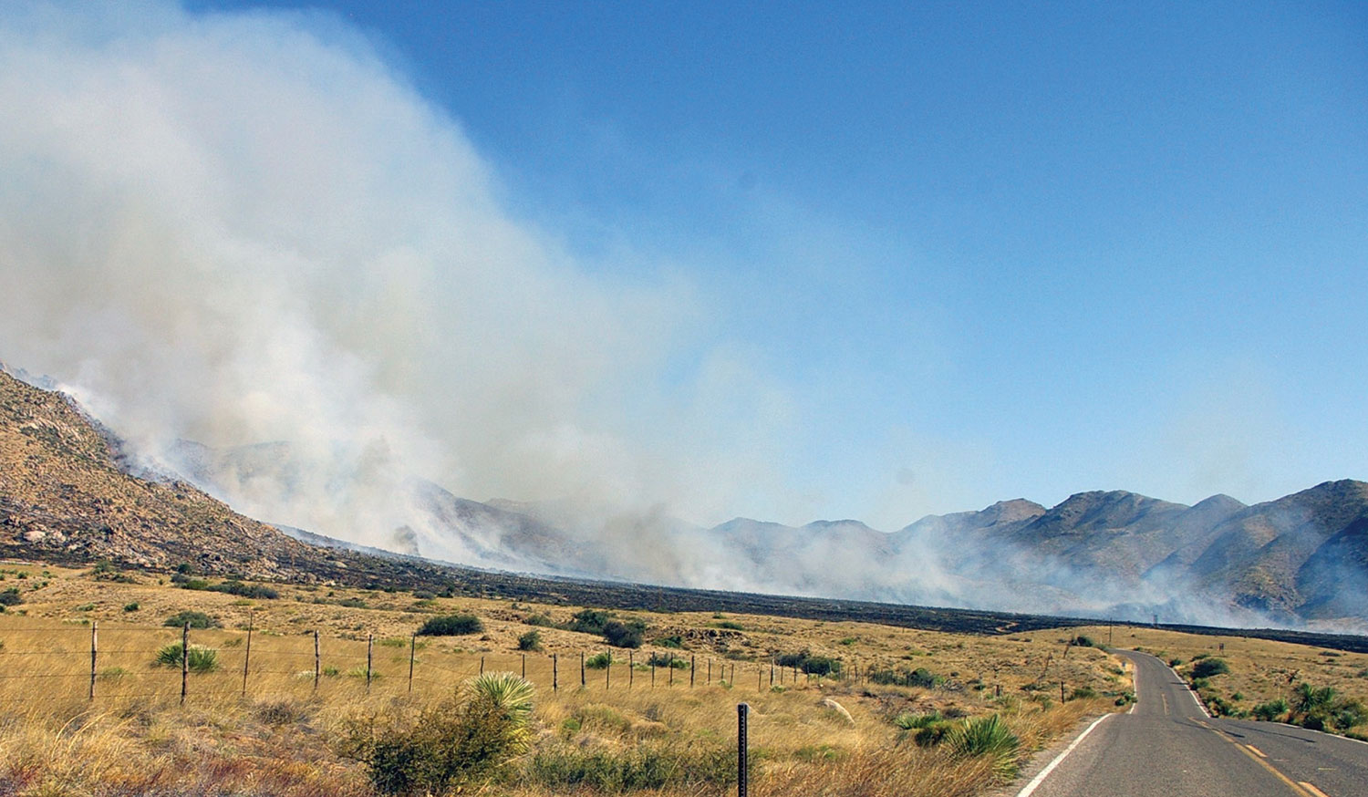
Battery Backed Up PV Systems Today. These newer systems are in high demand because of the frequent utility outages in some parts of the country due to severe storms, wildfires, unexpected weather events (unusually high or unusually low temperatures), and other conditions that stress the utility. See the lead-in picture.
The flooded lead-acid battery with vent caps that must be removed to add water on a regular basis is still used. But improvements in the form of valve-regulated lead-acid (VRLA) batteries are now with us as GEL cell batteries and as absorbed-glass-mat (AGM) batteries. These VRLA batteries are essentially sealed, and water cannot be added. They have a one-way vent that can allow hydrogen gas to escape when they’re subjected to excessive charging. The charging control for these types of batteries must be more precise than that used for flooded lead-acid batteries.
A more recent type of battery uses lithium-ion technology that is used extensively in batteries for automotive electric vehicles (EVs) and various assorted hand-held power tools. This type of battery, while more expensive than the lead-acid types, offers higher kWh of energy storage for a given size and weight and provides more charge and discharge cycles over the life of the battery. Due to thermal runaway issues when these batteries are improperly charged, a very sophisticated charge management system must be incorporated into each lithium-ion battery system.
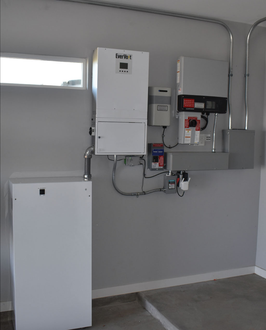
Lithium-ion battery banks can be used with separate multimode or stand-alone inverters. However, today’s trend is to offer factory-designed and built systems as fully engineered systems (see photo 6). These systems may include a multimode inverter (that may or may not regulate the charge of a lithium-ion battery bank), the battery bank charge management system, various electrical subpanels that are used for protected loads (battery backed up), main nonprotected loads, and the connections to the utility and the PV system. In many cases, the PV array connection to this system must be the AC output of a utility-interactive inverter (or multiple microinverters) or, in a few cases, a DC output. Various external options include peak-power tracking power optimizers for the DC PV system output and system-controlled contactors (relays) that can manage various loads and the connection to the grid. Nearly all systems include or have options to meet National Electrical Code (NEC) Article 690.11 and 690.12 requirements for DC PV array arc-fault detection and interruption and the PV rapid shutdown system.
These systems must be listed under one or more standards published by Underwriters Laboratories (UL) and tested and certified by one of the three Nationally Recognized Testing Laboratories (NRTL-UL, ETL, CSA). The system listing is particularly critical because these systems have a degree of complexity and differences to the extent that the NEC cannot specifically address the safe installation requirements for every system. NEC Section 110.3(B) is the overriding requirement where any listed system must be installed in accordance with the instructions provided with the product. And those listing instructions have been vetted and approved by the NRTL listing organization during the listing process. Also, the requirements in the UL Standards for Safety and by the listing NRTL will ensure that if there are any requirements in the NEC that would apply to these systems, these requirements are also met by the assembly. Such requirements would include those found in Article 712 (Direct Current Microgrid Systems), Article 705-Part II (Microgrid Systems), and Article 706 (Energy Storage Systems), in addition to the applicable requirements found in Articles 690 and 705.
Companies making these newer systems include Tesla, Generac, Enphase, Sonnen, Panasonic, and others. These systems may have a selection of optional battery modules than can be added to increase the stored energy. They are usually limited in power for operating protected loads in the absence of the utility based on the rating of the inverter(s). Pass through power from the utilities to protected loads and unprotected loads is based on the sizing of the various internal conductors and the various overcurrent devices, as well as the overall control strategy.
Most of these systems offer several programmable operating modes. These may include always maximizing the battery state of charge, depleting the battery at night (or at peak load time of the day) to minimize the power drawn from the utility, or other similar modes.
Looking Deeper
Plan Review. Prior to the field inspection. As mentioned above, these newer, battery-backed-up, factory-designed, and assembled systems are complex to the extent that the NEC does not provide detailed requirements for their installation. That implies that the inspector (and the PV installer) must become significantly more familiar with the installation and operation of these systems than the earlier systems to ensure the safety of the public. They will be installed primarily on dwelling units, but larger systems for commercial and utility use can be expected.
Although many jurisdictions do not have a plan review process or personnel to conduct that process, it appears that a plan review stage when dealing with these newer, more complex systems will be required. To facilitate that plan review, as has been mentioned in previous articles, the permit application should include, in addition to a complete three-line diagram, a full installation and operation manual for every piece of equipment that is in the system, including the equipment associated with the battery-backed-up system.
Because these are fully listed devices and equipment, the instructions for installation must be followed in detail, or the systems will not meet the requirements established by the listing process (NEC 110.3B). Not only is there a hardware requirement to be followed, but there is also a process by which the control software must be loaded and turned on properly. This information, for both hardware and software, is provided in great detail in the installation and operation manuals.
To fully inspect these systems for correct installation and operation, the AHJ will have to become familiar with the details in the various manuals. And that familiarization will probably take too long to do a quick read-through in the field. Additional time should be budgeted for the plan review stage in the office, which may entail additional inspection charges.
The Inspection. At all times, anyone working around or inspecting a PV system that has a battery or other energy storage system should exercise high levels of caution because these energy storage devices contain significant amounts of energy. Short circuits on conductors without over-current protection can result in arcs and sparks, fires as well as equipment damage. The AHJ should require that the installer perform all operations on the system and make all measurements that will be required to ensure proper installation and operation.
The requirements for installing the PV system dealing with the connection to the utility, the connection to any protected (battery backed up) loads, the connection to the PV system, and various grounding and disconnect requirements should be adequately covered by the existing requirements in the NEC. Because the systems are software controlled and monitor various AC currents in different parts of the systems, some of the existing code requirements on the sizing of busbars and conductors may no longer apply. These differences will be elaborated on in the installation manuals for the equipment.
The inspection should verify that all external, field-installed conductors in terms of types and sizes meet the requirements of the NEC. Grounding is critical and should follow code requirements. While the packaged system should internally meet NEC requirements established by Sections 705.11 and 705.12, some differences will be again described in the installation manuals. Where there is a DC interface or connectivity between the package system and the PV array, the requirements of Sections 690.11 (Arc Fault Detection and Interruption) and 690.12 (PV Rapid Shutdown System) should be verified and the PV Rapid Shutdown system exercised.
Because of the potential safety hazards associated with Lithium-Ion batteries, the installation manual may have special location and mounting restrictions for the system. These may include outdoor locations for the battery bank or even the entire system if it is a one-piece unit. Many of the enclosures are outdoor rated, but this should be verified.
Summary
More frequent utility outages due to storms, wildfires, and unexpected weather events create demand for PV systems that can supply this missing energy. The battery-backed-up PV system can meet those requirements, and multiple manufacturers are producing such systems. These more complex PV systems with energy storage are not fully addressed by the requirements found in the NEC. The fully listed systems are controlled by software and have internal power control systems that, to some extent, may supersede various NEC requirements. Although it will require more effort and study on the part of the AHJ, the information in the manuals for this equipment must be used to verify a code-compliant installation. These newer systems and those that follow should be an excellent reason to establish a plan reviewer position in each jurisdiction. At the very least, additional time in the office for each inspection should be allocated to perform the plan review before the actual field inspection.