
Safety First — for the Inspector
Photovoltaic (PV) power systems are generally inspected to ensure that they have been installed in compliance with the National Electrical Code and local code requirements. A thorough inspection of a PV system will ensure that those requirements have been met and that the safety of the public is generally achieved.
Although many AHJs have inspected numerous PV systems and developed procedures for doing so, there is a continuing flow of new inspectors into the inspection community and some of them are combination inspectors with limited experience in expecting any electrical system. Even for the seasoned PV inspector, safety (for the inspector) should be a paramount consideration when approaching a PV system for inspection purposes. The material below is presented in a manner that will allow the AHJ to select what portions of the system he or she can inspect with safety and as allowed by their local jurisdiction.
PV systems on residences can have open-circuit voltages in cold weather up to 600 volts direct current (dc). Under the 2014 NEC, commercial PV systems (not on a dwelling unit) may have open-circuit voltages of 1000 volts dc, and some utility-scale units may have dc voltages approaching 1500 volts. And, stand-alone, off grid PV systems and utility-interactive PV systems with battery backup will have batteries capable of generating very high short-circuit currents, possibly up to 15,000 amps.
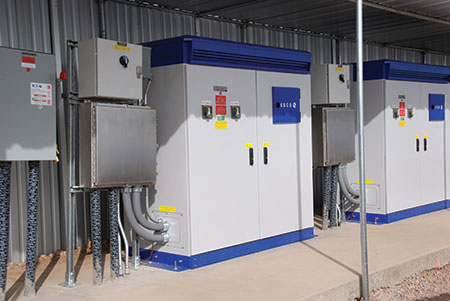
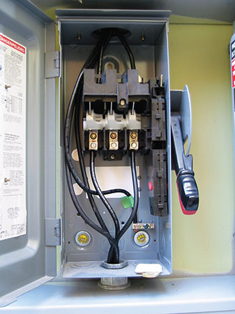
PV voltages on the ac side of the system for dwellings will typically be 240 volts with a sprinkling of 208-volt three-phase systems. On the commercial systems and utility-scale systems the voltages will typically be 208, 480 and even higher on premises wiring that should be inspected (photo 1).
Do the Plan Review First
A plan review, in the office, should proceed an actual on-site inspection of a PV system. See the “Perspectives On PV” article in the September-October 2014 IAEI News for a discussion of what can best be done when sitting behind a desk, in a heated or air-conditioned office, looking at a set of plans that hopefully have been submitted during the permitting process. The plan review, even an informal one done by the inspecting official will save significant amounts of time and can reveal code violations that may not be visible on site. These violations, of course, should be corrected prior to the on-site inspection.
Approach with Caution
If the inspector has numerous PV systems under his or her belt and the PV installer has installed numerous systems that have been inspected by the jurisdiction and have been found satisfactory, then the inspection will go smoothly and quickly. However, if the inspector has little experience with PV systems and the installer is relatively new to the business, some degree of care and caution must be exercised when inspecting the systems to ensure the safety of the inspector and to ensure adequate compliance with the code requirements.
The overall workmanship of the installation can be viewed without touching any of the equipment. Hopefully, good workmanship indicates a high degree of code compliance, but this is not necessarily always the case.
The inspector should always require that the PV installer and/or designer be present during the inspection to handle the opening of equipment and to answer questions. PV inverters and combiners are generally not familiar pieces of electrical equipment to the inspector nor are they standardized in their means of opening or the operation of controls. The AHJ should require that the installer or other competent person who is familiar with the system open or operate all equipment, even a simple disconnect switch.
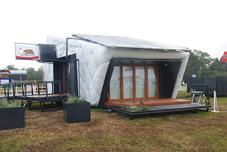
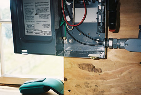
Provisions to access all equipment and the PV array should be made by the PV installer. Locked buildings or rooms must be opened, and in some cases, on utility-scale systems, a representative of the local utility must grant access to the system. Where rooftop inspections are going to be conducted, the AHJ should require that rooftop access be made available through either permanently mounted ladders on commercial buildings or through the use of a ladder provided by the PV installer. (See photo 2.)
Grounding — First, Last, and Always
Grounding is a mundane subject, but the inspector must always keep in mind that the PV power system will be generating dangerous voltages and currents for perhaps 50 years or more. Proper grounding, particularly equipment grounding, is paramount to the long-term safety of the public. While the inverters may stop functioning and not be repaired or replaced, the PV module can be generating substantial amounts of voltage and possibly current for a long period of time. These systems are installed on the roofs and in not-readily-accessible locations that could indicate that they may not be inspected or serviced regularly by anyone looking for deterioration in the wiring or in the grounding of the system. In the author’s opinion, grounding is one of the most important aspects of code compliance that the inspector can look for to ensure the safety of the system for decades.
The prudent inspector will look for external signs of proper grounding for the PV system before touching any part of the system. These would include new connections to the premises grounding electrode and possibly visible grounding electrode conductors routed to the PV equipment.
Most PV inverters and DC combiners currently require surface mounting and metal raceways between the combiner on the roof, if any, or the modules; and the inverter should be readily visible and be properly installed in terms of support and the tightness of fittings. Although the EMT conduits themselves are sometimes used as equipment grounding conductors in PV systems, frequently a separate equipment-grounding conductor will be installed inside these conduits from the roof to the equipment located below. This internal equipment grounding conductor does not alleviate the requirement to properly terminate and connect all pieces of metallic raceway, because under fault conditions, those metallic raceways still may carry fault currents and when properly grounded provide shock protection and to some extent fire protection.
What Was Installed?
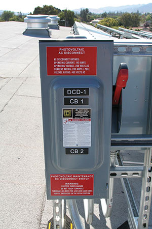
At this point, it is possible to read the labels on equipment that is accessible and verify that the installed equipment is consistent with the equipment shown on the plans. For numerous reasons, including contract and delivery delays, permitting delays and other situations, frequently the installed PV equipment including the modules and the inverters does not match the plans that were approved. This is a significant issue because as the equipment changes, the specifications change and the various code requirements applying to that installed equipment may be different than the requirements for the original equipment. And from time to time, the incorrect equipment has been installed such as dc disconnects with voltage ratings less than the dc voltage of the system or ac and dc disconnects that have been interchanged with a resulting incorrect (too low) rating for the dc disconnect. (See photo 3.) If the initial inspection reveals any of these issues, it’s time to go back and have a new permit application and set of plans submitted for the as-installed system.
To the Roof or Not?
Inspecting a PV array that is roof-mounted in a not-readily-accessible area is somewhat problematic. For example, some jurisdictions have insurance policies that prohibit the inspector from going on the roof of a house or even the roof of a commercial building. Ground-mounted PV arrays are much easier to inspect and commercial PV arrays on flat-roofed commercial buildings are relatively easy also if permanent ladders are provided. In many cases, on a sloped roof PV installation, the module mounting, the rack mounting and the equipment-grounding connections can be viewed from the edge of the roof by standing on a ladder without going on the roof. These details should match the instruction manuals for each product and any details shown in the plans. New building codes requiring setbacks from the roof edge for Fire Service access may make this type of inspection more difficult.
If a rooftop inspection of these installation details is not possible, then the inspector might consider querying the installer about the details of the module grounding, the details of the module mounting and the details of the rack mounting including any flashing. These verbalized details could be compared with the instruction manual requirements for the module and the rack and any flashing that would appear in the plans submitted with the permit request.
A more detailed inspection might involve entering the attic of the building and verifying that the attachment devices for the PV rack have been firmly attached to the building trusses and are not merely driven into the roof sheathing.
It is not unusual on larger systems that the installing organization will provide a cherry picker or scissor-jack manlift equipment to provide easy and safe access to the roof. This equipment is usually used on site to make the initial array installation and could be retained for the inspection. Each jurisdiction will have to decide what their local requirements will be to perform an adequate inspection of the entire PV system.
Get That Equipment Opened Up!
The installer, upon request should open up all readily accessible equipment enclosures including dc combiners, inverters, disconnects, load centers and any non-standard equipment. With this equipment open, the inspector can view workmanship including properly terminated circuit conductors, conductor size markings, and conduit terminations as well as equipment grounding connections.
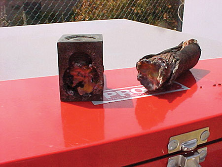
Double lugging is more common than we would like in PV systems due to the necessity of adding surge suppression or lightning arresters and data acquisition system (DAS) sensor leads. In some installations, fine-stranded, flexible PV wire/PV cable has been used and improperly terminated in dc combiner boxes that have terminals that are not listed for use with fine-stranded, flexible cables (110.14). (See photo 4).
Color codes for dc and ac wiring may be inspected at this point. The inverter manual will indicate whether the array is operated as grounded (transformer or isolated inverter) or ungrounded (transformerless or non-isolated inverter). The type of grounding for the array will determine the color codes used in the dc wiring and the number of poles that must be switched in the dc disconnect as well as the conductors that must be fused in the dc source and dc output circuits. Grounded circuit conductors must have white, gray or three white or gray stripes (depending on the code year in the jurisdiction), and ungrounded conductor must not have any of these colors [200.6(A)].
Ungrounded conductors must be switched in dc disconnects and where there are more than two strings of modules being combined, normally there must have a fuse or other overcurrent device in each of the ungrounded conductors (690.8, 690.9). This generally means that for grounded PV systems, there will be only one conductor of each circuit switched in the disconnect and only one conductor will have overcurrent protection where multiple conductors are combined. For an ungrounded system, both of the circuit conductors will be disconnected and both of the circuit conductors will have overcurrent protection when there are multiple source circuits being combined [690.35(B)]. (See photo 5).
Metal raceways connected to dc combiners, disconnects, and inverters should be properly terminated and in most cases use grounding-bonding bushings. Most listed disconnects show, on the label, the correct grounding kit to be used for equipment grounding of the disconnect. NEC Section 110.3(B) requires that the labels on listed equipment be followed and it would be a code violation to use a separate lug and a sheet metal screw instead of the specified grounding kit. (See photo 6).
Operational Tests for Safety
There are three relatively easy operational tests that can be done to help ensure that the system is operating correctly and in a safe manner. These tests involve proper wiring and the operation of the inverter.
The inspector should have the installer open the dc disconnect to the utility-interactive PV inverter while the inverter is producing power. The inverter should immediately cease producing power as indicated by the display panel on the inverter. If the installer has an ammeter or wattmeter available, the inverter output current or power should go to zero as indicated by these instruments.
A second test is also conducted while the inverter is producing power. The main ac disconnect for the building or structure should be opened. Again, the inverter should immediately stop producing power since its anti-islanding circuits should sense the lack of the utility signal and should shut the inverter down. It is best to use the main disconnect for the building or structure so that there are loads in parallel with the inverter output which might, under some circumstances, cause the inverter to continue running and support these loads. This is an undesirable condition. In some installations, it is not advisable to shut down the ac power to the entire building or structure because of the need to keep equipment running in the building or structure. If this situation exists, then at the very minimum, the ac disconnect on the output of the inverter or the backfed breaker that the inverter feeds should be opened and the inverter output should go to zero. This is not as stringent a test as removing power from the inverter with loads paralleled on the output of the inverter, but it does serve to give some indication that the anti-islanding circuits are working in the inverter.
If the system is a utility-interactive battery-backed-up system or a stand-alone system with batteries, another simple test can be conducted. With utility power or any backup power generator disconnected from the PV system, the installer should open the dc battery disconnect. The portion of the electrical system powered by the standalone inverter or the protected load circuits on the standalone output of the multimode inverter should cease receiving power. Any failure of these tests indicates improper system wiring or a failed component.
Summary
Inspections of PV installations are somewhat different than inspections of normal electrical power systems. Caution should be exercised to ensure the safety of the inspector during the inspections because of the unique nature of PV systems with the higher voltages and currents involved. The PV installer is a necessary part of the inspection process and should be required to open equipment and to operate equipment with the inspector observing the system during these actions. This inspection coupled with a plan review prior to the inspection should generally allow verification that the requirements of the National Electrical Code have been met.
The Southwest Technology Development Institute web site maintains a PV Systems Inspector/Installer Checklist and all copies of the previous “Perspectives on PV” articles for easy downloading. A color copy of the latest version (1.93) of the 150-page, Photovoltaic Power Systems and the 2005 National Electrical Code: Suggested Practices, written by the author, may be downloaded from this web site: http://www.nmsu.edu/~tdi/Photovoltaics/Codes-Stds.html .