
Power systems analysis is considered a very broad subject that can be broken into different elements and principles according to the electrical engineering field. Under this umbrella, coordination studies are considered one of the most important studies that must be implemented from the moment the first site plans are designed and blueprints are generated. Enforcing coordination requirements go back to the year 1993 when they started as one standard when designing escalators and lifts. 2005 was the year when the requirements of these studies were expanded to include emergency systems, standby systems, and health care facilities.
Nowadays, many international codes and standards have dedicated sections to emphasize the importance of having the equipment onsite passing the coordination requirements [1]. Such as; NFPA 110 [2], NEC Article 700.28 and Article 701.27 [3], IEEE 141: (former IEEE Red book) [4], IEEE 242 (former IEEE Buff book) [5], IEEE 399 [6], IEEE 1584 [7], IEEE 3002.3 [8], NFPA 70E [9], IEEE 241 [10], ANSI C57.12.00 [11], ANSI C37.13 [12], and ANSI C37.010 [13], ANSI C 37.41 [14], and CSA Z462 [15].
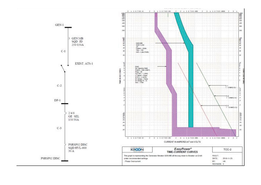
A coordination study, in general, is used to evaluate the effect of equipment failures and fault currents within a power system and to help analyze the impacts on the system operation. Theoretically, to be able to run this study, a model of the distribution system has to be built and simulated on one of the power systems software. Furthermore, this requires collecting all the related data from the site under study, as per NEC requirements [3], after which a comprehensive model analysis of the system is performed on a simulation tool to come finally coming up with a list of graphs and recommendations. The generated graphs from this study are called TCCs (Time-current Characteristic Curves). The main task is to identify areas of miss-coordination by comparing different curves from the equipment on the same branch or network. Finally, adjustments are done for each case, thus ensuring the best achievable coordination, and minimizing the impact of events of equipment failure. Refer to Figure 1.
When conducting a coordination study, the term “Selective Coordination” always comes up. Having the system performing under this state means that all overcurrent protection devices’ opening times are designed so that the circuit breakers and/or fuses located close to faults open first. Furthermore, selective coordination can be achieved by employing several methods. One method would be by comparing the different TCCs (time-current curves) on a specific branch and trying to adjust them on a time-wise base. A reliable source to selectively coordinate the protective devices is using coordination tables (Usually published by the equipment manufacturer). From the curves, engineers can determine how long it takes for a protective device to clear a fault for a given amount of fault current.
Note that, TCC graphs rely on the information obtained from a previously conducted short circuit analysis to determine where the device’s time-current curve is cut off. The principle is that each of the devices will have its characteristic cut-off at the maximum fault current available for the bus it is connected to.
In a properly coordinated system, the protective devices are selected and adjusted to minimize the impact of equipment failures within. Furthermore, coordination studies analyze the characteristic curves of fuses and breakers and compare them against one another on log plots (see figure 1).
The main challenge in the industry is the fact that many electric power distribution systems are not designed with protective device coordination in mind. Although a distribution system can be successfully designed for minimum losses and minimum upfront investment, it could still fail the proper coordination of the protective devices, which will result in a shutdown of the entire facility in case of failure. Note that, a failure, as simple as a single motor or branch circuit within a building can result, in the shutdown of most of a facility. The effect of a single failure is not limited to time loss, but it can result in extensive damage to the equipment and may introduce hazards to plant operating personnel.
II. Coordination studies and industry needs
Up to this point, the discussion in this paper has been on the theory behind coordination studies. In this section and onwards, the focus will be on the practical side. Points such as specific site parameters, budgetary control, and site readiness are missing from many discussions. Power studies are meant to help create a safer environment for everyone on-site, and meant to extend the health of equipment, and meant to eliminate the possibility of a full power outage on site.
One of the challenges in the industry is that people tend to choose between two extremes; either follow an RFM (Run to Failure Maintenance) model or pile studies on the shelves every year with no sense of how to fully take advantage of the results.
Everything comes at a cost, and selective coordination, as an example, makes for a more expensive electric system. Having said that, the NEC’s primary interest is in the safety of humans. It requires selective coordination only in systems that directly affect life safety. When it comes to coordination, there is no rule of thumb that fits all sites. While in some locations, the requirement could be coordination to 0.1 seconds, other locations can go to about 0.01 seconds.
According to the NEC, selective coordination is only required on the emergency-power-source side of the electric system. The reason is that when normal power is interrupted, the emergency system should take over to provide the necessary power. In situations where the normal power protective devices are not properly coordinated with the downstream protective devices, an upstream device could trip first leading to a full power outage (the whole system goes out of service).
Power blackouts are considered a frequent occurrence in industrial facilities. Reasons for these incidents can vary between faults from the utility side or, as simple as, faults on the load ends of the feeders. What they have in common is that if the facility is not ready to handle them properly, it will cost a lot of money. See Table 1 below [16].
| Industry | AVG downtime coasts /hr |
| Brokerage Services | 6.48 M$ |
| Energy | 2.48 M$ |
| Telecom | 2 M$ |
| Manufacturing | 1.6 M$ |
| Retail | 1.1 M$ |
| Health care | 636 k$ |
| Media | 90 k$ |
Table 1. Estimations for downtime costs
- Common electrical anomalies and code violations
As mentioned previously, a full site evaluation should be the first item on the list when budgeting for a coordination study. The main reason for that is the fact that any part of the electric distribution system which doesn’t follow the international codes and standards will not benefit from applying hundreds of studies over and over.
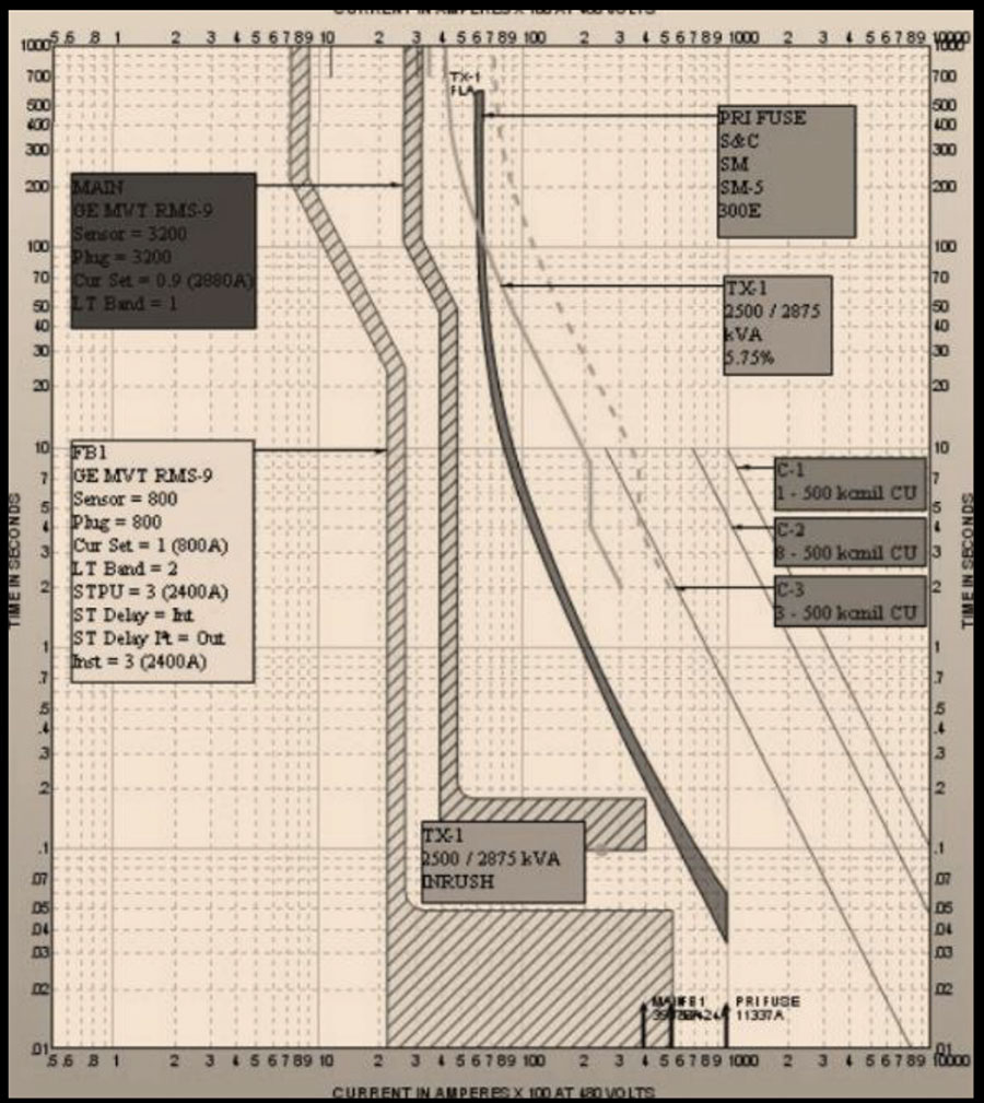
Figure 2 shows an example of a theoretical well-coordinated system, where the cables are well protected and properly sized; the transformer curves are well coordinated with the protective devices, and the branch breaker curve is to the left of the main breaker (selective coordination is achieved). Even though the study in this example was able to achieve the requirements, if the system on-site is not well maintained and/or not fully examined, the results won’t matter anymore.
Having said that, in this section, a discussion based on these example parameters will be presented to give more insights into some of the common violations and anomalies that can be found on-site. Note that these examples are from real buildings in North America.
(a) Cable protection:
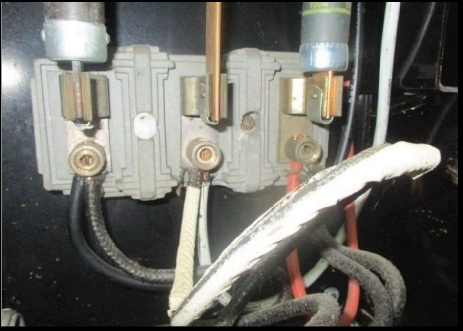
Cables are the veins of any electric system. Having them properly sized and installed not only guarantees a smooth operation but also eliminates the chances of getting an arc flash incident or a fire on site. While coordination studies can easily point out if the cables are well protected, and if the sizes of the cable are properly chosen, as seen in Figure 2, it won’t be effective if the cables are not installed properly according to the codes, Figure 3 illustrates some common problems that can be seen widely.
![Figure 3. Examples of common anomalies in cables, “a” and “b”: loose connections, “c”: uneven torques on the connectors, and “d”: improper cable sizes. [Note: three of the photos show improper termination of more than one conductor for the termination.]](https://iaeimagazine.org/wp-content/uploads/2022/08/2022-09-Huth-FIG3.jpg)
(b) Fuses on site
Another example of an area where coordination studies can help is designing the rating for fuse boxes on-site. As discussed in the introduction section, the key is to have downstream protective devices picking faults before upstream devices. Applying this concept is easy on paper, but the question that is worth asking here is: How confident are we that the fuses are installed properly on site, and how much do they reflect the data on the SLD (Single Line Diagram)? As an example, Figure 4 shows a fuse box with one of the fuses replaced with a piece of metal. If this is the case on-site, what is the point of conducting a study before addressing similar problems?
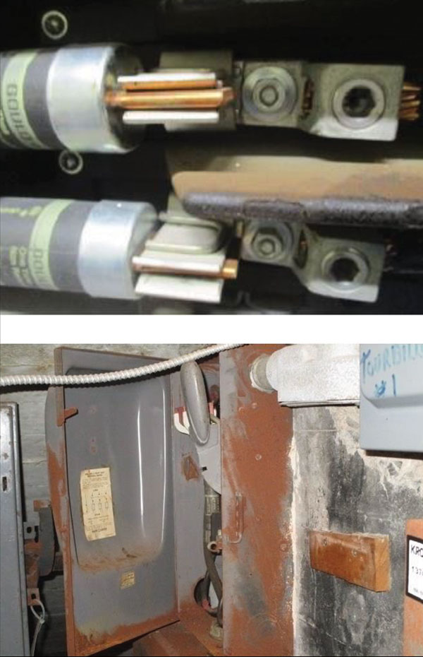
Another common violation is having cases of a fuse-mismatch in some fuse boxes. Figure 5 illustrates this code violation. Note that more than half of the sites in North America have those cases of mismatch in at least a couple of boxes per facility. Reasons for these could be the lack of supplies from one type; misunderstanding of the difference between the kA rating (short circuit withstand capacity) and the current rating; and/or lack of training for personnel on-site. Either way, the critical point here is that, in most cases, these mismatches won’t be addressed on SLDs.
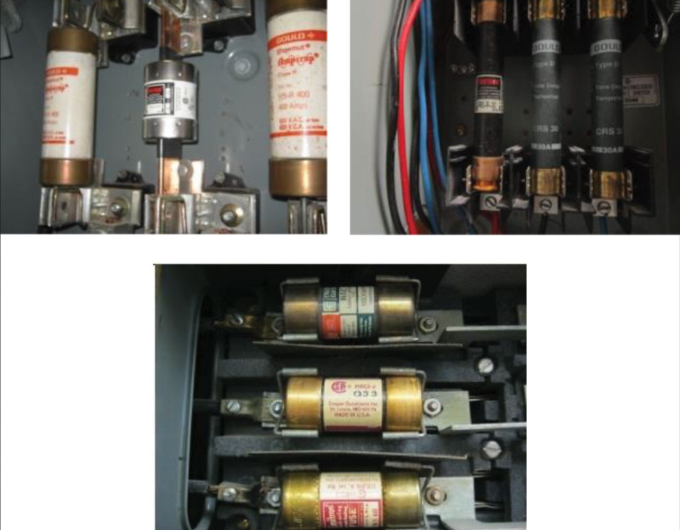
In addition, Figure 6 displays other anomalies that can be found on different sites.
(c) Circuit Breakers (CBs):
The concepts discussed in part b (Fuses) apply here. Having a circuit breaker on an SLD with a written type, ratings, and perhaps the trip unit settings (if any) can’t be considered a reliable source for data collection purposes.
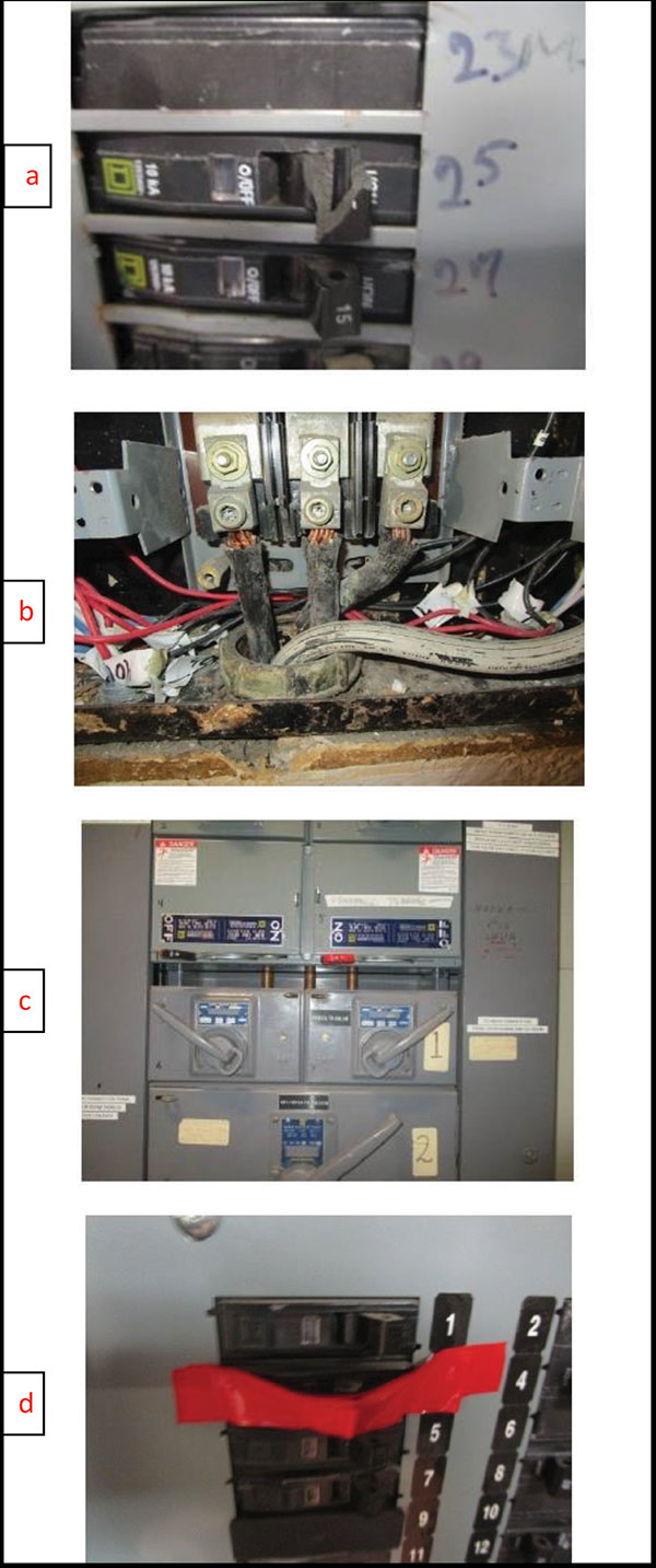
Having proper visual inspections for each circuit breaker is a must. As mentioned, the goal of coordinating a certain circuit breaker with its upstream and downstream is to avoid system-wide blackouts. The big question should be whether the installed breakers are well maintained according to the codes and manufacturer datasheets. Figure 7 shows examples of some violations that should be addressed to comply with the codes and international standards and to avoid a site disaster before proceeding with a coordination study.
(d) Transformers
Transformers are passive electric devices that help transfer the required electrical energy from one section of the electric system to another. Coordination studies tackle transformers in a way that ensures the upstream and downstream protection devices help maintain a safe and uninterrupted operation under events of an inrush current, for example, and protect them from any fault currents. Having said that, any coordination study should focus on every single transformer in the distribution system.
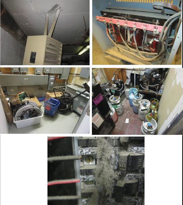
Without proper maintenance and without following safety measures, the results of the study around transformers will not help achieve the safety goals. Cases of common violations vary between the improper installation of the transformer body itself, poor maintenance of the internal wiring and structure, and in many cases, treating electrical rooms as an extra storage space for random objects (see figure 8).
Furthermore, other common problems that can be seen on different sites include, for example, jammed mechanisms due to improper installations of the equipment. Refer to Figure 9.
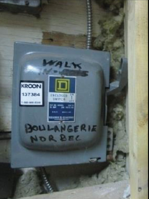
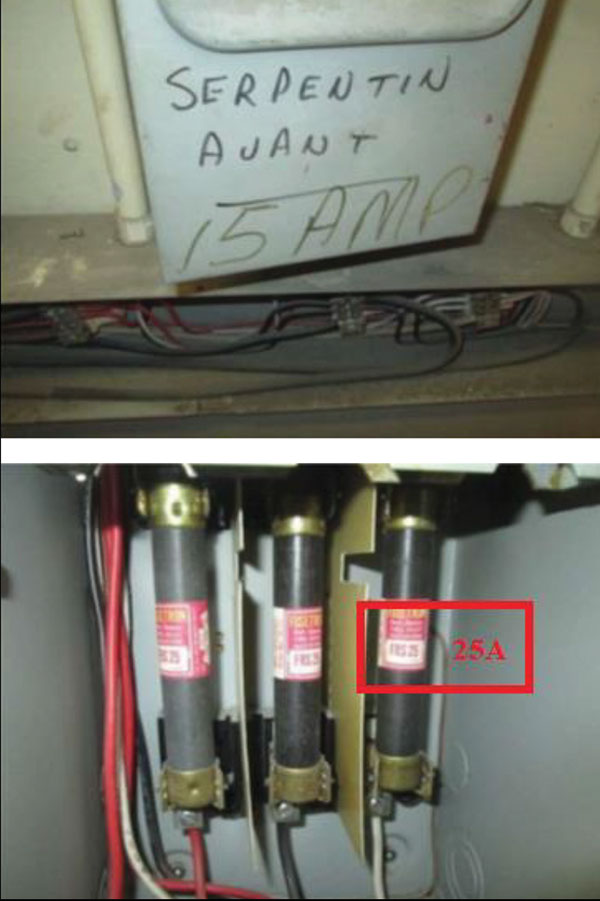
As an example of how unreliable a quick scan of equipment can be, Figure 10 displays a fuse box that shows 15A on the cover while having 25A fuses installed within.
From the previous examples, it is clearly important to fully evaluate the site as part of the study budget. Having a simulation as accurate to the electric distribution system as possible helps avoid a lot of future problems and loss of profit. In addition, bad practices include using SLDs as the main source of data, using outdated equipment databases, using quick inspection rounds, and more.
III. Main considerations prior to running a coordination study.
From the discussion and examples in the previous sections, it is now clear that the budget isn’t just limited to the number of TCCs generated multiplied by the hourly rating of the engineering time. In fact, to properly budget for a coordination study, a list of any recent electric equipment failures that caused extensive and expensive downtime to the operations, and any recent upgrades to the current electric distribution system as a result of system expansion or general maintenance should be considered. Examples of upgrades include adding a UPS system, or an emergency generator on-site. Other points to consider are listing areas with critical equipment or inventory that could be damaged in case of a power outage, or if it has been more than five years since the last study [9][15].
To sum up, the main factors when setting a budget should include costs of:
- A full site visit, to cover all equipment and report all anomalies. This visit should also help investigate circuit location, device manufacturer and type, current transformer ratios and range of adjustment, IEEE device number, recommended settings or device size, and referenced time-current curve.
- Solving all problems and setting up a safety procedure to follow on-site (According to the codes and IEEE standards).
- Decide on the type of coordination scheme to be implemented (example: selective coordination requires a licensed professional engineer).
- Proceed with updating the SLDs (if needed) to meet the actual implementation of the electric system on site.
- Identify the critical equipment per section in the building as a high priority in the study.
- Identify current problems the site encounter, such as racing events, and high incident energy values on arc flash labels in some areas on-site and identify possible hot spots using IR scans (with equipment covers off).
- Count the number of scenarios implemented on-site, between emergency and normal feed. (Usually, this means that a full study has to be implemented for each scenario)
- Obtain the utility provider site data.
- The software license to simulate the study
- Obtain any previous short circuit and arc flash studies are done within the last five years.
- On-site training for the team
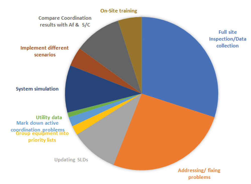
To give a better idea of the contribution of each of the eleven steps, Figure 11, illustrates the percentages of time required to follow the items on the list based on a worst-case scenario. Note that these percentages were obtained based on 100 industrial site requirements from the past five years.
In addition to the previous points, a common approach to counting the number of TCCs needed to cover the full coordination study is to count the buses in the SLD. Having said that, while some buses around equipment are easy to count, a UPS for example could be implemented using more than 10 buses and all should be considered.
Note that, some parts of the electric system could cost more than others. For example, buses between the main electric service entrance, relays, and distribution transformers are considered more complex to work on than load sides for example.
IV. After the Coordination study
As illustrated, coordination studies are conducted as per the latest international standards and safety codes (i.e.: IEEE, NEC, ANSI & NFPA standards). Outcomes of the study are usually in a form of recommendations meant to improve the overall reliability of the electric system, improve the fault isolation at each point, reduce the likelihood of power outages within the facility under study, save the existing protective device from damage, minimization unwanted events such as; nuisance tripping events caused by different loads, helps with transformer inrush currents, reduce arc flash incident energy in some areas (could be achieved by changing the trip unit settings), prevent damage by identifying underrated equipment, and prevent damage by identifying overloaded equipment.
The report and documentation can vary depending on the facility requirement. Some of the common sheets that are usually attached to the final report can include contractor notification forms, workplace safety observation forms; employee training recommendations; job briefing, and planning checklists; and risk assessments for equipment with current arc flash labels, and for equipment that does not.
Furthermore, TCCs and recommendations in the report can be divided into two groups. The first group consists of cases that can be solved through changing trip unit settings, load distribution, and cable sizes, which is mostly considered a cheap and easy fix. The second group of recommendations is in areas where a major equipment upgrade is a must. Example: If the circuit breaker causing the problem doesn’t have an electronic trip unit, or in other cases where the branch has multiple fuses that do not meet the selective coordinate specifications.
Finally, in order to address all the recommendations and fully take advantage of the coordination study report, a plan has to be set to prioritize urgent problems, such as an unprotected transformer, and schedule later for unnoticeable scenarios, like having some odd possibilities for a racing event between low voltage branch equipment (unless it is a visible issue on-site).
V. Conclusions
It is always important to look at the electric distribution system as a “living” entity. This implies that it actually changes significantly over time, as the equipment is upgraded or replaced, utility interconnection parameters change, and/or systems are enhanced/expanded. Having said that, facility circuit protection and coordination should be performed based on the actual state of equipment on-site. Furthermore, it should be performed in association with short-circuit and arc flash studies every five years (unless a major change has happened).
The best practice is to always start with setting goals to achieve from any power study such as: assuring maximum personnel safety, minimizing equipment damage, and maintaining system reliability. These goals have to accompany proper system maintenance according to the international codes and standards.
References
[1] NFPA 70, “National Electrical Code,” Article 620, 2020.
[2] NFPA 110, “Standard for Emergency and Standby Power Systems,” 2022.
[3] NFPA 70, “National Electrical Code,” Article 700.28, 2020.
[4] IEEE 141, “Recommended Practice for Electric Power Distribution and Coordination of Industrial and Commercial Power Systems,” 1993.
[5] IEEE 242, “Recommended Practice for Protection and Coordination of Industrial and Commercial Power Systems,” 2001.
[6] IEEE 399, “Recommended Practice for Industrial and Commercial Power System Analysis,” 1997.
[7] IEEE 1584, “Guide for Performing Arc-Flash Hazard Calculations,” 2018.
[8] IEEE 3002.3, “Recommended Practice for Conducting Short-Circuit Studies of Industrial and Commercial Power Systems,” 2018.
[9] NFPA 70E, “Standard for Electrical Safety in the Workplace,” 2021.
[10] IEEE 241, “Recommended Practice for Electric Power Systems in Commercial Buildings,” 1990.
[11] ANSI C57.12.00, “Standard General Requirements for Liquid-Immersed Distribution, Power, and Regulating Transformers,” 2015.
[12] ANSI C37.13, “Standard for Low Voltage AC Power Circuit Breakers Used in Enclosures,” 2015.
[13] ANSI C37.010, “Standard Application Guide for AC High Voltage Circuit Breakers Rated on a Symmetrical Current Basis,” 2016.
[14] ANSI C 37.41, “Standard Design Tests for High Voltage Fuses, Distribution Enclosed Single-Pole Air Switches, Fuse Disconnecting Switches and Accessories,” 1981.
[15] CSA Z462, “Workplace electrical safety,” 2021.
[16] “IT Downtime: How to Calculate the Costs and Control the Risks,” CGSINC, 2016. https://www.cgsinc.com/blog/it-downtime-calculate-costs-control-risks (accessed May 12 2022).