Some features of electrical circuits and electrical systems are so fundamental they have appeared in some form in every edition of the National Electrical Code. These include insulation for wire type conductors, conductor (wire) sizing, and overcurrent protection for circuits (fuses or circuit breakers). Another long-time electrical safety requirement is grounding of electrical systems and equipment for safety. The grounding of metal electrical equipment and metal enclosures has been practiced in some quarters since the use of electricity began. This article will focus on grounding and bonding requirements as they relate to metal parts and metal equipment of electric signs and neon installations.
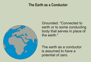
Figure 1. The term “grounded” is defined in the NEC in Article 100
Fundamentals
The term “grounded” is defined in the NEC in Article 100 as, “Connected to earth or to some conducting body that serves in place of the earth.” The earth as a conductor is assumed to have a voltage potential of zero. Conducting bodies that serve in place of the earth can include, but are not limited to, conduit, metal enclosures, transformer cases, raceways, etc. Basically when metal equipment is grounded it is connected to the earth. (See Figure 1).
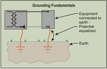
Figure 2. Grounding or earthing metal electrical enclosures puts both the earth and the metal enclosure at the same potential (voltage).
This can be accomplished in a few different ways. A metal object such as a box or other equipment enclosure that is grounded by connecting (bonding) it to the earth by means of an equipment grounding conductor to a grounding electrode conductor and, finally, to the grounding electrode (the conducting element connection to earth) of the system is thereby forced theoretically to take on the same zero potential as the earth. Grounding or earthing metal electrical enclosures puts both the earth and the metal enclosure at the same potential (voltage). (See Figure 2).
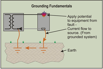
Figure 3. When a grounding conductor (could be a wire, conduit, or raceway) is broken, is inadequate in size, is not connected or has a poor connection, a hazardous, above-ground potential on the metal object may be present, creating a shock and fire haza
Any attempt to raise or lower the potential (voltage) of the grounded objects results in the passing of current (amps) over the grounding path until the potential (voltage) of the objects and the potential (voltage) of the earth (zero) are equalized. Usually, this above-ground potential is caused by a line- (hot conductor) to- ground fault. With both the metal enclosures and earth at the same potential (electrically), shock hazards are reduced and an electrically conductive path for any fault current to flow is established. When a grounding conductor (could be a wire, conduit, or raceway) is broken, is inadequate in size, is not connected or has a poor connection, a hazardous, above-ground potential on the metal object may be present, creating a shock and fire hazard. (See Figures 3 ,4 and 4a).
Grounding Electrical Systems and Equipment
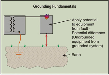
Figure 4. When a grounding conductor (could be a wire, conduit, or raceway) is broken, is inadequate in size, is not connected or has a poor connection, a hazardous, above-ground potential on the metal object may be present, creating a shock and fire haza
The grounding of an electrical system and equipment is usually accomplished at the electrical service equipment of a building or structure. The grounded conductor (usually the neutral or white conductor) and metal enclosure of the electrical service are connected to the earth by using a grounding electrode conductor which connects to a grounding electrode system. [See figure 5]
Once this system and metal enclosures are grounded, the power is then distributed to the electrical panels with feeder conductors (the larger conductors supplying power to the electrical panel) that include an equipment grounding conductor, and finally to the branch circuit conductors (the conductors between the final fuse or circuit breaker in the electrical panel and the electric sign or neon transformer enclosure), which include an equipment grounding conductor for grounding the non-current-carrying metal parts of electrical equipment. These equipment grounding conductors are the extension of the grounding circuit, and as a result, are the conducting body that serves in place of the earth. (See Figure 6)
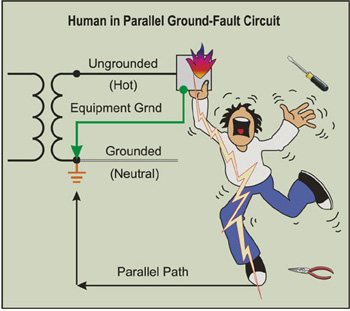
Figure 4a. When a grounding conductor (could be a wire, conduit, or raceway) is broken, is inadequate in size, is not connected or has a poor connection, a hazardous, above-ground potential on the metal object may be present, creating a shock and fire haz
Bonding of Electrical Enclosures and Metal Parts
Bonding of electrical equipment and enclosures simply means that the enclosures will be connected together in an appropriate manner to ensure electrical continuity and to ensure the capacity to conduct safely any fault current likely to be imposed on those enclosures. When a metal conduit is connected to a metal electrical junction box with a proper conduit connector or proper fittings, the two parts become one electrically because they are bonded together. (See Figure 7)
It is important that all connections and metal continuity be installed and maintained wrench tight. Wrench tight is a workmanship issue. The pride of workmanship must be held in high regard to comply with the rules and safety aspects of electrical installations contemplated by the NEC. It is important that care be taken to tighten locknuts and setscrews of all fittings as they enter electrical enclosures (i.e. junction boxes, timeclocks, electrical panels, transformer boxes, etc.). Loose connections can lead to arcing conditions when conduit or equipment grounding circuits are called upon to carry fault current. Loose connections can also lead to isolated metal equipment and enclosures, which become a silent and sometimes lethal shock hazard when energized.
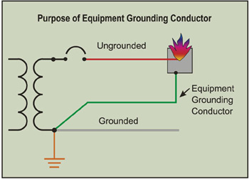
Figure 5. Purpose of equipment Grounding Conductor
The Scope and Purpose of Grounding
The scope of grounding and bonding and the general requirements of grounding and bonding are contained in Section 250-2 of the National Electrical Code. These requirements include:
• Grounding of electrical systems,
• Grounding of electrical equipment,
• Bonding of electrically conductive materials and other materials, and
• Performance of the fault-current path.
Using the National Electrical Code
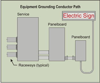
Figure 6. These equipment grounding conductors are the extension of the grounding circuit, and as a result, are the conducting body that serves in place of the earth.
The Code requirements for electric signs and neon installations are found in Chapter 6, Special Equipment, and specifically in Article 600 of the NEC. Grounding and bonding requirements for electric signs and neon installations are outlined in Sections 600-7 and 600-32. It should be pointed out that all of the Code rules in Article 250 are applicable to signs and neon installations unless the rules in Article 600 modify or amend those general requirements.
Section 90-3 of the NEC explains the basic arrangement of the Code. Chapters 1 through 4 apply generally, except as amended by Chapters 5, 6, and 7 for the particular conditions. The NEC contains the minimum requirements for electrical installations that are essentially safe, thus one must do at least that much. The main purpose of the NEC is the protection of persons and property from the hazards that arise from the use of electricity.
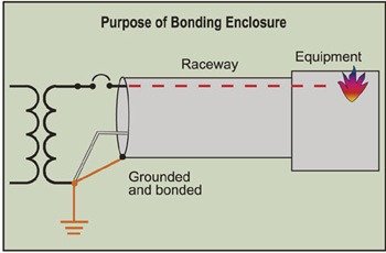
Figure 7. When a metal conduit is connected to a metal electrical junction box with a proper conduit connector or proper fittings, the two parts become one electrically because they are bonded together.
Back to Basics—The Path for Normal Current and Ground Fault Current
It is important to have a basic understanding of the paths for electrical current. For electrical current to flow properly it must have an adequate path. In the normal electrical circuit, current will seek out the source, taking any and all paths to try to return to that source.
In order for an electrical circuit to work properly, the circuit must be complete.
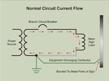
Figure 8.
In other words, for electrical current to flow in the circuit to an electric sign, the common 120-volt circuit usually will contain an ungrounded conductor (hot) and a grounded conductor (neutral). When properly connected, normal current will flow in this circuit. (See Figure 8)
The other type of current one must be familiar with is fault current, which will also follow all paths available to it to try to return to the source. Fault current in most cases is an abnormal or accidental situation. It is important that a proper path for fault current, in the form of a conductor, be provided with the circuit for safety. This conductor is referred to as the equipment grounding conductor of the circuit. With all metal parts and enclosure associated with the sign or neon installation effectively bonded together and connected to an equipment grounding conductor, two basic but important things are accomplished. First, the metal enclosures and parts are essentially put at the same electrical potential (voltage). Second, if a ground fault should occur in the circuit, an effective path is provided back to the source and to ground which ensures overcurrent device operation.
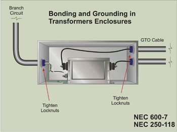
Figure 9.
The equipment grounding conductor and proper bonding are essential elements for safety in electrical signs and neon installations. This safety component of the circuit acts as the silent servant waiting to perform its ever-important function.
The high voltage secondary circuits (GTO in a wiring method that extends from the transformer to the discharge tubing) for neon installations also introduce another electrical component into the electrical circuit. This component is called capacitance. Capacitance coupling can actually raise the potential (voltage) on ungrounded metal equipment and metal parts. Proper grounding and bonding of metal enclosures and associated metal parts ensure that these parts remain at earth potential. Other electrical resource material on electrical theory is available that expands on this term.
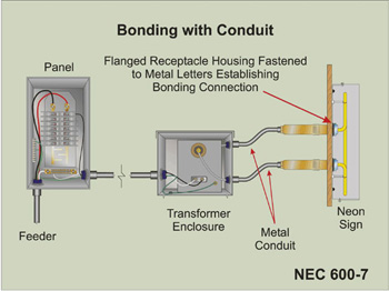
Figure 10.
Electrical installations for sign circuits and neon installations are not exempt from these basic safety requirements. Transformers installed and wired using the balanced mid-point reference wiring method require the secondary output conductors to be as short as possible, and the secondary return leads must terminate on a mid-point grounding connection terminal provided for that purpose by the transformer manufacturer.
Proper grounding and bonding connections of the entire branch circuit wiring methods and secondary circuit wiring methods are critical for proper operation and safety of these secondary circuits wired by this mid-point reference method. Mid-point reference wiring methods are just mentioned in this writing and will be expanded upon in further writings.
The Sign and Neon Branch Circuit Wiring Methods
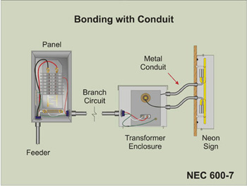
Figure 11.
All conductors of the branch circuit supplying power to a sign or primary (line side, usually 120-volt input) of a neon transformer are required to be installed in the same raceway, cable, trench, wiring gutter, unless permitted otherwise by the NEC. This includes all conductors (wires) of the circuit, including the equipment grounding conductor, which can be in many forms. It can be in the form of a conductor, conduit, tubing, cable armor, or combination of cable armor and conductor. (See Section 250-118 of the NEC).
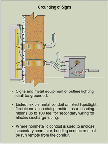
Figure 11a.
In Article 600 of the NEC, there are requirements for branch circuits supplying signs and outline lighting systems. The wiring method (cable, conduit or raceway) used to supply signs and outline lighting systems must terminate within the sign, outline lighting system enclosure, junction box, or a conduit body. This circuit that terminates at the sign or neon transformer or power supply enclosure contains the equipment grounding conductor for the circuit. This conductor should be terminated to the metal enclosure. (See Figure 9)
This termination should be made by use of approved means. Sheet metal screws (tek screws) are not acceptable for attachment of equipment grounding conductors per the NEC. (See Section 250-8). Proper grounding clips, screws, or lug type terminations are available for this purpose.
This termination of the equipment grounding conductor establishes the connection to ground for those enclosures and puts them at the same zero voltage potential as the earth. Section 600-7 of the NEC requires signs and metal equipment of outline lighting systems to be grounded. The Code also allows for listed flexible metal conduit or listed liquidtight flexible metal conduit (per Article 351 of the NEC) to be used as a bonding means in lengths not exceeding 100 feet. (See Figures 10 and 11) One should keep in mind that there is a length limitation on secondary GTO conductors of 20 feet when installed in metallic wiring methods and 50 feet when installed in nonmetallic wiring methods. See Section 600-32(j).
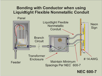
Figure 12.
Small associated metal parts not exceeding 2 inches in any dimension, and not likely to become energized (such as the metal mounting means for tubing supports), and spaced at least ¾ inch from the neon tubing are not required to be bonded. Where listed liquidtight nonmetallic conduit is used for installing the secondary high voltage GTO conductors from the transformer or power supply to the neon tubing and where there are associated metal parts that require bonding, a bonding conductor is required to be installed. (See Figure 11a) This bonding conductor is required to be installed separate and remotely spaced from the nonmetallic conduit. It should be pointed out here that this wiring method is not electrical nonmetallic tubing, which was deleted from the 1999 NEC as an acceptable wiring method for GTO secondary conductors. See Section 600-32 of the NEC. The wiring method referred to here is rigid nonmetallic conduit.
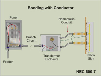
Figure 13
A spacing of 1½ inches is required to be maintained when the secondary circuit operates at 100 Hz or less. When the secondary circuit operates at over 100 Hz, the spacing requirement increases to 1¾ inches. (See Figures 12 and 13). This conductor is required to be not smaller than No. 14. Metal parts of a building or structure are not permitted to be used as a grounded or equipment grounding conductor.
Summary
Proper grounding and bonding is a basic requirement in the NEC and is found in Chapter 2, which is appropriately titled, “Wiring and Protection.” The minimum Code requirements are set forth to protect persons and property from the hazards that arise from the ever-expanding use of electricity. Following these basic minimum requirements for grounding and bonding of signs and neon lighting installations contributes to the safe use of electricity.
The Code requirements in this writing are based on the 1999 edition of the National Electrical Code. Always consult the local authority having jurisdiction if in doubt as to the NEC requirements or any local amendments or requirements.
This article is being published in the January 2000 issue of Sign Business Magazine.