
Article 240 of the National Electrical Code (NEC) covers overcurrent protection and notes that all electrical conductors shall be protected. Overcurrent protective devices (OCPDs) consist of fuses and circuit breakers. Both were patented by Thomas Edison — the circuit breaker in 1879 and the fuse in 1890. Although fuses were the first OCPDs to be widely used in homes and commercial buildings, circuit breakers have also had a rich history of protecting electrical installations and are very common today. This article covers the basics of panelboards, switchboards, and switchgear, which are the three main options for organizing, housing, and utilizing the OCPDs. For simplicity, only breakers will be referenced here in discussing OCPDs.
In each of these three types of gear, there are electrified copper or aluminum buses to which the breakers are attached. Wires then connect the breakers to the electrical loads they feed. Each of the three types of gear has unique characteristics, and there are various situations where each is preferred over the others. A brief description of each type of gear and a table of common characteristics are provided to help identify the preferred application of each type of gear.
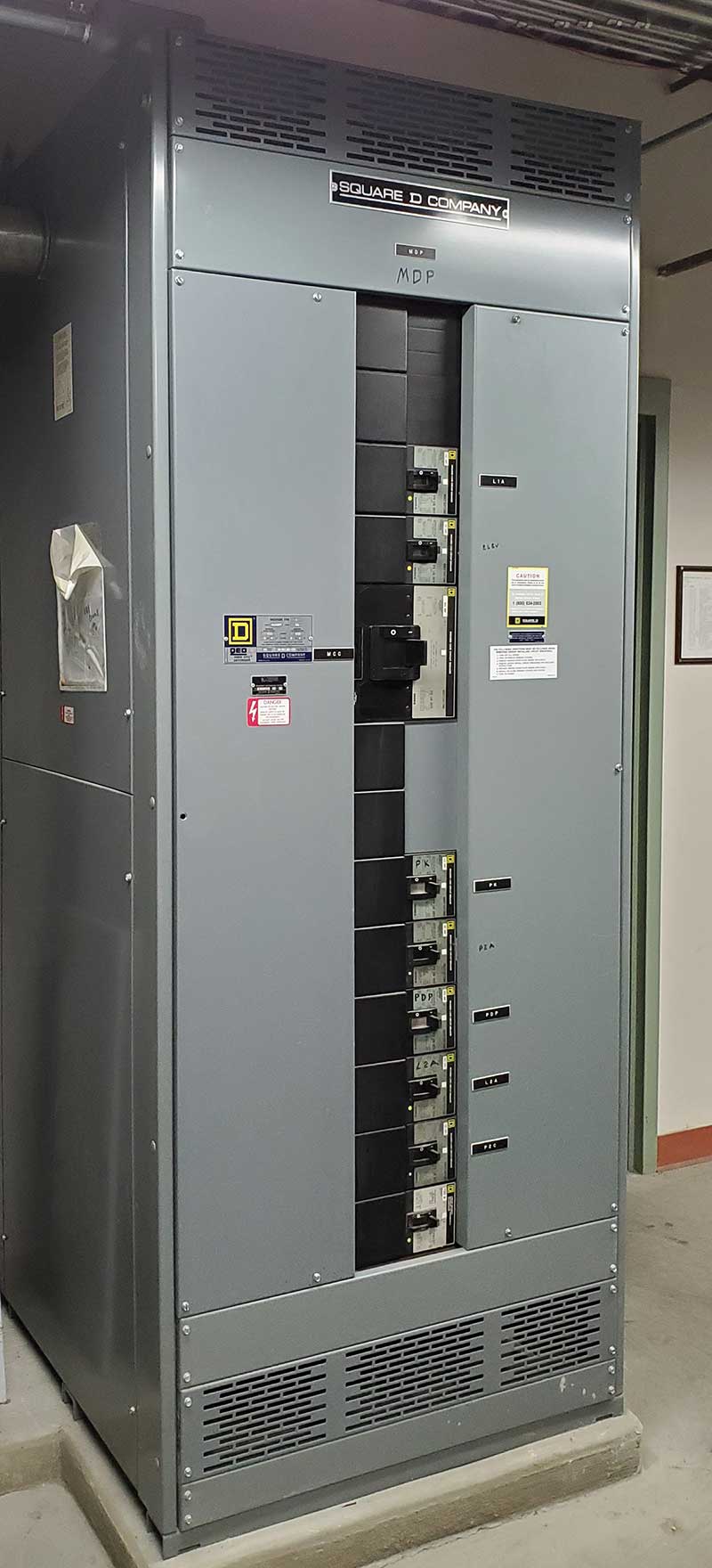
Panelboards. The NEC defines a panelboard as: “A single panel or group of panel units designed for assembly in the form of a single panel, including buses and automatic overcurrent devices, and equipped with or without switches for the control of light, heat, or power circuits; designed to be placed in a cabinet or cutout box placed in or against a wall, partition, or other support; and accessible only from the front” [NEC 100]. These can be divided into load centers and panelboards, both of which are often referred to as “Panels.”

Load centers are commonly used in residential and small commercial applications. Since nearly every house in America has one, they are the least expensive way to accommodate circuit breakers. The breakers themselves are usually less expensive because they are mass-produced and simply plug into the load center bus. Load centers are primarily intended for applications up to 240V and are normally only rated up to 225A. At those ratings, they are shallow enough to recess into a 2×4 stud wall and narrow enough to fit between studs on 16″ centers. With larger, surface mount enclosures, one manufacturer offers load centers rated up to 600A. Also, voltages up to 277V can be obtained, but are not common.
Both load centers and panelboards are mounted in cabinets “. . . provided with a frame, mat, or trim in which a swinging door or doors are or can be hung.” [NEC 100] As required in NEC 408.38, they also have dead fronts, meaning that there are no “. . . live parts exposed to a person on the operating side of the equipment” [NEC100]. Normally, panelboards are used for voltages up to 600V, but higher voltage ratings are also available. Panelboards can be rated for up to 1,200A. Smaller panelboards can accommodate plug-in or bolt-on breakers. Larger panelboards only utilize bolt-on breakers and can have a standard thermal-magnetic trip or electronic trip breakers with adjustable settings. Panelboards are deeper than load centers. The wall into which a recessed panelboard is mounted must be constructed using 2×6 studs. Panelboards rated 600A, and higher are deeper and surface mounted on the wall.
Switchboards. Switchboards are defined in the NEC as “A large single panel, frame, or assembly of panels on which are mounted on the face, back, or both, switches, overcurrent, and other protective devices, buses, and usually instruments. These assemblies are generally accessible from the rear as well as from the front and are not intended to be installed in cabinets” [NEC 100].
Switchboards are similar to panelboards in that they are normally rated for up to 600V, but they can handle higher fault currents than panelboards and load centers. They are floor mounted and are deeper than panelboards, usually starting at 18″ deep. Since switchboards are larger and more expensive than panelboards, they are seldom used for bus ratings less than 1200A and can be rated for up to 5,000A. Both bolt-on breakers and draw-out breakers can be installed inside a switchboard line-up. Often, just access to the front is required, but rear and side access may also be required.
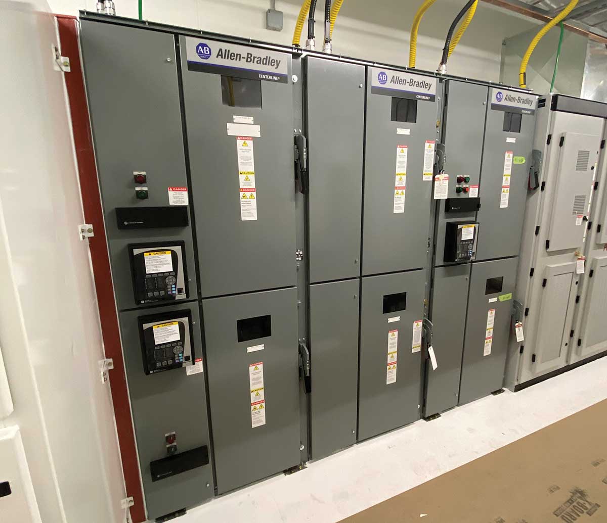
Switchgear. The NEC identifies switchgear as: “An assembly completely enclosed on all sides and top with sheet metal (except for ventilating openings and inspection windows) and containing primary power circuit switching, interrupting devices, or both, with buses and connections. The assembly may include control and auxiliary devices. Access to the interior of the enclosure is provided by doors, removable covers, or both.”
Switchgear is the largest of the three. It can be rated for up to 38 kV and can have current ratings up to 6,000A. Normally draw-out breakers are used, and therefore, access to the front and rear of the gear is required. Switchgear is tested to a different UL standard than panelboards and switchboards. Because the breakers in switchgear are each in their own compartment, the gear is rated to withstand a short circuit condition for up to 30 cycles. Panelboards and switchboards are only rated to withstand a short circuit condition for up to 3 cycles.
Switchgear often utilizes draw-out breakers. These breakers can be detached from the bus and removed for maintenance or replacement without shutting down the main or affecting the other breakers in the gear lineup. With moving parts, a draw-out breaker does need to be maintained on a regular basis to ensure that the mechanisms are adequately lubricated and will function properly when required. Working with the breaker energized also requires particular attention to potential arc fault dangers, and personal protective equipment must be utilized.
When One Type Of Gear Is Preferred Over The Others
Factors that drive decisions about which type of gear to use include economics, space constraints, utility service requirements, ability to shut down the facility, and the electrical system size (voltage and current ratings).
- Economics often drive decisions regarding which type of equipment to use. If the loads are few and small, a load center may do the job. Since specialty enclosures can get very expensive, if the environment requires such an enclosure, the smallest feasible panelboard is normally used.
- Required space for switchboards or switchgear frequently becomes an issue, especially in a leased facility where square footage equals income to the owner. Wherever possible, panelboards are used to minimize wall and floor space needed for the electrical equipment.
- In order to meet the utility’s service requirements, or to save space inside, often the main service switchgear is mounted outside the building. This alleviates the need for a Current Transformer (C/T) enclosure for the service entrance, as a section of the gear can accommodate the utility C/Ts and meter.
- Shutting down the electrical system for maintenance may not be economically feasible in industrial or critical operation facilities. Therefore, switchgear with draw-out breakers is used.
- Depending on the facility’s power requirements, switchboards or switchgear may be needed for the main distribution equipment. However, for the economic and space considerations noted above, panelboards are used wherever possible throughout the building.
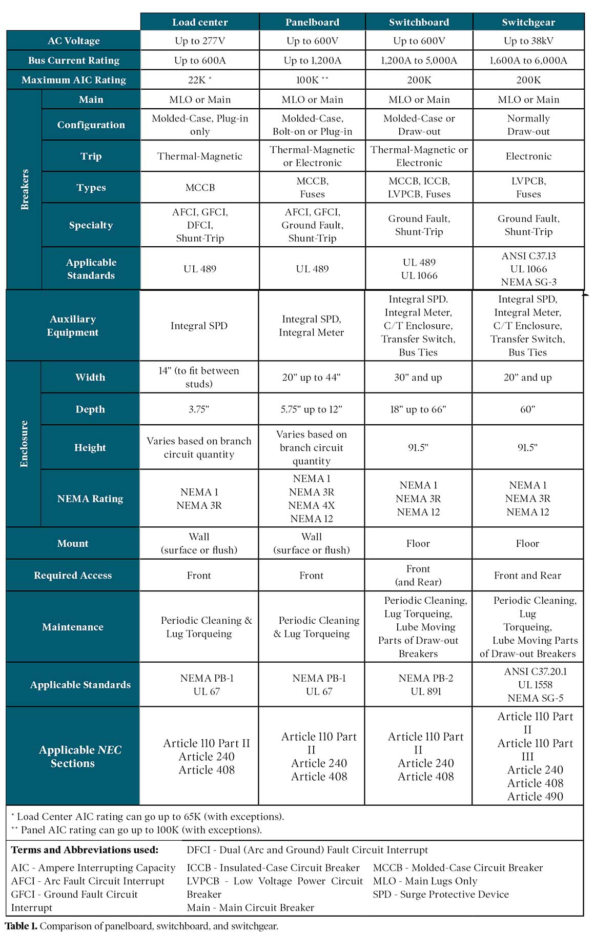
Panelboard, Switchboard, Switchgear Comparison Table
The following table provides a comparison of the various aspects of the different styles of gear. Note that the NEC does not limit the use of any gear types to particular voltages or current ranges. These are products that the electrical gear manufacturers have created to meet the Code requirements and the needs of the electrical construction industry. This table is based on gear ratings and sizes by ABB, Eaton, and Schneider Electric for equipment commonly used in residential and commercial facilities. Industrial facilities may use gear by other manufacturers with additional ratings and sizes.
Conclusion
With options of panelboards, switchboards, and switchgear, the electrical system designer has a robust palette of options to provide the required overcurrent protection for conductors throughout the facility. Based on whatever factors are in play at a particular facility, there are always workable solutions.