
Example Calculations
Now that we have a series of equations relating to power, voltage, current, and resistance, I want to crank through some simple example calculations.
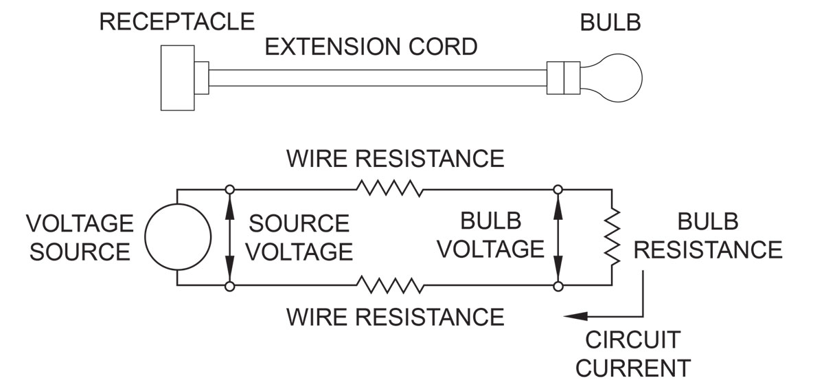
Problem 1: I want to operate a 60-watt light bulb temporarily in a chicken coop 100 feet from my house to keep some chicks warm at night. We will assume the outside air temperature is constant at 20°C (68°F). I have a 100-foot extension cord with 18 AWG copper wire. What voltage do I need at the house receptacle to ensure the voltage at the bulb is 120 V? The circuit diagram looks like figure 4.
The resistance of the 18 AWG copper wire at 20°C is 6.39 W / 1000 ft per manufacturer’s data. Since the cord is only 100 feet long, the resistance of the wire is one-tenth of 6.39 or 0.639 W. The resistance of the 60-watt bulb operating at 120 volts is 240 W, as calculated previously. Note that the amount of power the bulb uses, and the bulb’s light output vary with operating voltage. If the bulb voltage is below 120 V, the bulb uses less power, the light output is reduced, and the bulb’s life increases. Likewise, if the voltage is greater than 120 volts, the bulb uses more power, the light output is greater, and the life of the bulb decreases.
The receptacle at the house is the source of EMF (voltage). How much current is flowing in the circuit? We know that the voltage across the bulb is 120 volts and the power the bulb is using is 60 watts. From this information, we can calculate the current in the circuit using equation I = P / V = 60 W / 120 V = 0.5 A. If the bulb were connected at the source receptacle, the source voltage and the bulb voltage would be the same. In this example, the bulb is connected to the source receptacle by a 100-foot extension cord. The resistance of the extension cord reduces the voltage that gets to the bulb. This reduction in voltage is called voltage drop.
Since we know the resistance of the extension cord and how much current is flowing in the extension cord, we can calculate the voltage drop using equation V = I circuit x R extension cord = 0.5 A x 0.639 W = 0.3195 V. This is the voltage drop in just one wire of the extension cord.
There is also voltage drop in the other wire, so we have to multiply the voltage drop times two. The total voltage drop in the extension cord is 2 x 0.3195 V = 0.639 V. This voltage drop is quite low because the current is low. If we were trying to use a 1500 W electric heater at the end of the same extension cord to heat the entire chicken coop, the voltage drop would be so high the heater would produce much less heat. For the light bulb circuit to deliver 120 volts to the bulb, the source voltage will have to be 120 V plus the voltage drop in the extension cord or 120.639 V.
Problem 2: Let’s consider the problem of heating the entire chicken coop with a 1500 W electric heater at the end of the same extension cord. Note that the nameplate rating on the heater is 1500 W at 120 volts. When the voltage is lower than 120 volts, the heat output of the heater goes down. When the voltage is above 120 volts, the heat output goes up. What source voltage do we need at the house so that the heater gets 120 volts?
We can calculate the current the heater draws using equation I = P / V = 1500 W / 120 V = 12.5 A.
We can calculate the voltage drop in the extension cord using equation (1) V = I circuit x R extension cord = 12.5 A. x 0.639 W = 7.9875 V. Again, the voltage drop is in both wires of the extension cord, so we have to multiply by two. The total voltage drop = 2 x 7.9875 V = 15.975 V. In this case, the source voltage would have to be 120 V + 15.975 V = 135.975 to maintain the heater voltage at 120 V. I wired up the above example in my lab with the source voltage at 120 V. With the 100-foot extension cord, the voltage at the heater was only 105.1 V and the circuit current was 10.5 A.
Using equation (4) P = V x I, the amount of power the heater was producing was only 105.1 V x 10.5 A = 1103.55 W. Note that the reduced voltage at the heater greatly reduces the heat output of the heater. The voltage drop in the extension cord was 120 V – 105.1 V = 14.9 V. Using equation (3) R = V / R, the resistance of the extension cord wire is 7.45 V / 10.5 A = 0.709 W. I used half the voltage drop in the equation because half the voltage drop is in each wire. Note that this resistance is higher than the manufacturer’s data. One difference might be because the manufacturer’s data was at 20°C (68°F). When I did the test, the room temperature was 80°F, and this test was not the first one I did with the extension cord. You will recall that the resistance of the wire produces heat.
That heat gradually raises the temperature of the wire. As the temperature increases, the resistance of the wire increases. After several tests or after running one test for several minutes, the wire within the extension cord may be considerably hotter than 68°F. Using equation (7), we can calculate the amount of heat being produced by each wire of the extension cord. P = I 2 x R = 10.5 A x 10.5 A x 0.709 W= 78.16 W. The total heat produced by the extension cord is two times that produced by each wire or 2 x 78.16 W = 156.32 W. This type of wasted power is called loss. Not only is it important to use adequate wire size to ensure the heater gets the correct voltage and produces the expected amount of heat, but it is also important to reduce the losses.
In this example, the total power being used by the circuit is 1103.55 W + 156.32 W = 1259.87 W. Only 1103.55 W or 87.6 % is being used where we want it in the chicken coop. The other 12.4% is heating up the back yard. If we left the circuit running for several hours, the heating of the extension cord might eventually cause the wire to melt and start a fire. Note that the 15-amp fuse or breaker that protects the 14 AWG copper house wiring will not protect the 18 AWG extension cord.
That’s another story I will eventually get to. If I had used an extension cord made with 12 AWG copper wire (1.59 W/ 1000 feet), the voltage drop in the extension cord would only be 3.975 volts, and the heat loss associated with the extension cord would only be 49.68 W.
Instrument accuracy
The accuracy of an instrument is a statement of the largest allowable error expressed as a percentage. Seventy years ago, the most accurate instruments were ones designed to measure one thing. For example, the Weston DC voltmeter had six voltage ranges, 0 to 25 millivolts (0.025 volts), 0 to 50 millivolts, 0 to 500 millivolts, 0 to 5 volts, 0 to 50 volts, and 0 to 150 volts.
The accuracy of the instrument is described on the meter in the following manner: “This instrument indicates International Volts and is correct within ½ of 1% of the full-scale value at any part of the scale at 75°F.” That means that the limit of inaccuracy for this instrument connected on the 0 to 150-volt scale is 0.005 x 150 = 0.75 volts plus or minus (±).
By “plus or minus,” I mean the reading could be off by as much as 0.75 volts high or low. In comparison, the Fluke Model 175, digital multimeter, set to measure DC volts ranges from 0.1 millivolts (0.0001 volts) to 1000 volts. The limit of inaccuracy for the instrument is ± 0.15% of the reading.
That means the limit of inaccuracy when the meter is reading 120 volts is 0.0015 x 120 = 0.18 volts. The limit of inaccuracy when the meter is reading 1.0 millivolts is .0015 x 1 millivolts = 0.0015 millivolts (0.0000015 volts). The Fluke multimeter also measures AC volts from 0.1 millivolts to 1000 volts, DC and AC amps from 0.01 milliamps to 10.00 amps, and resistance from 0.1 W to 50.00 MW (50 million W). I will talk about measuring currents greater than 10 amps in another segment.
Resistance variation with temperature
Earlier, I calculated the resistance of the filament of a 60-watt light bulb to be 240 ohms. That is the resistance when the bulb is energized at 120 volts. If you connect the terminals of a 60-watt bulb to a digital multimeter set to measure resistance, the meter will read about 17 W. The reason the multimeter measures 17 W is that the multimeter is measuring the resistance of the filament at room temperature. When the bulb is energized at 120 volts, the temperature of the filament is around 2200° F. When the bulb is first energized, for an instant, the current drawn by the bulb is 120 V / 17 W = 7 A.
In the first few milliseconds after closing the switch, the current heats up the filament from room temperature to 2200°F, the resistance changes from 17 W to 240 W, and the current drops from 7 A to 0.5 A. If we wire an ammeter in the bulb circuit, the ammeter would not measure the surge in current because it happens too quickly. The bulb filament is a perfect example of the resistance of material increasing with temperature.
The multimeter can measure the temperature of the filament at room temperature because the voltage being applied to the bulb by the multimeter is very low, typically 0.5 to 1.5 V. If the multimeter applies a voltage of 1.5 volts to measure resistance, the initial current in the bulb filament per Ohm’s law (equation 2 of part two) is the voltage divided by the resistance, 1.5 V / 17 W = 0.088 A (88 milliamps).
That is a very low current, and yet if you continue to measure the resistance of the bulb filament with the multimeter for a few minutes, you will notice the resistance of the filament gradually increasing. That is because the 88 milliamp current is heating up the filament. The instrument measuring the resistance of the bulb filament is changing the resistance.
Instrument effect on the quantity being measured
When we use instruments to measure quantities like voltage, current, and resistance, it is very important that the instrument doesn’t affect the quantity being measured. Voltmeters must have a very high internal resistance, and ammeters must have a very low resistance to keep the instrument from affecting the quantity being measured.
The Weston DC voltmeter, vintage 1936, has an internal resistance of 3000 W when connected on the 0 to 150-volt scale. In contrast, the Fluke digital multimeter, vintage 2004, has an internal resistance of 10 MW (10 million W) when set on the DC voltage scale.
In general, modern multimeters have very little effect on the voltage, current, or resistance being measured in electric power circuits. When measuring these quantities in electronic circuits, the same is not always true.
Alternating Current
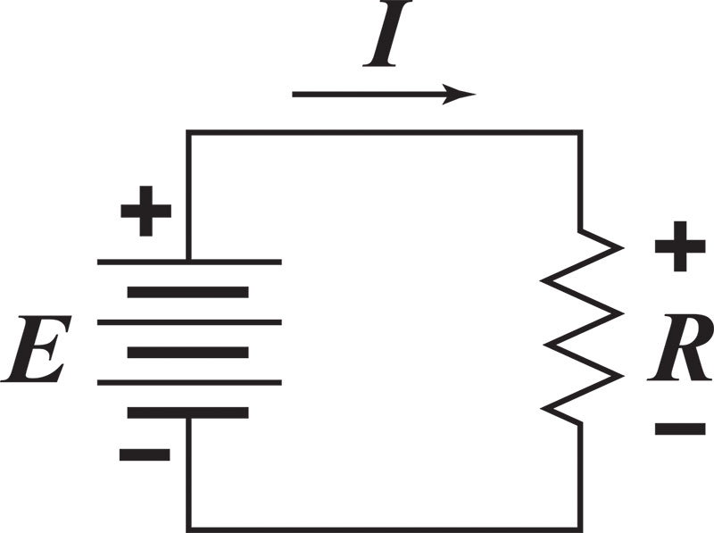
Up until now, I have been talking about dc, direct current, in which the current in the circuit travels in one direction. Batteries and other sources of dc are marked with what we call polarity marks, + and –. When a battery is connected in a circuit, the current comes out of the positive (+) end of the battery and returns to the battery at the negative (–) end.
This is true for all sources of dc. If we connect the test leads of a volt-ohm meter (VOM) to a battery with the red colored positive (+) lead connected to the positive end of the battery and the black negative (–) lead connected to the negative end of the battery, the voltage reading on the display will be positive. Most VOMs do not display a plus sign (+) for positive readings, but they do display a negative sign (–) for negative readings. If we swap the leads by connecting the red lead to the negative end and the black lead to the positive end, the VOM will display a negative voltage. For loads, elements of a circuit that use electricity, the voltage that appears across a load is positive at the terminal in which current enters the load and negative at the terminal where the current exits the load (see diagram 1).
The other type of current is called ac, alternating current. In alternating current, the magnitude and polarity of the voltage and current are continuously changing. At one instant in time, the current flows in one direction. A moment later, the current flows in the opposite direction. Alternating current is often pictured graphically by diagram 2, a graph of voltage with respect to time. This graph of voltage versus time is often called a sine wave.
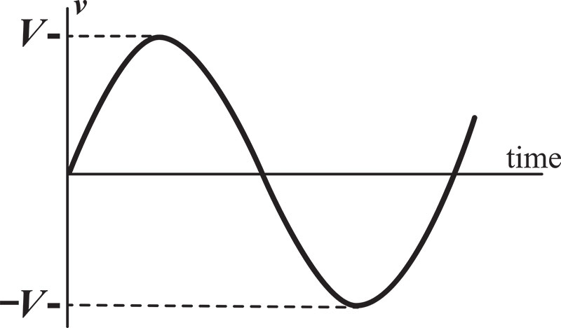
For most electric power sources in the U.S., the frequency is 60 cycles-per-second or 60 Hertz. That means that the voltage and current complete a complete cycle sixty times per second. Looking at diagram 2, the voltage starts off at magnitude. The voltage increases with time until it gets to a maximum and then decreases with time until it gets back to 0. During this first half cycle, the current flows in one direction. Then the current reverses, and the voltage increases back up to a maximum and then decreases back down to 0. In this second half cycle, the current flows in the opposite direction.
At this point, 1/60 of a second or 16 2/3 milliseconds have passed. The voltage reverses and starts the next cycle, identical to the first cycle. When ac was first generated, it was difficult to measure the voltage of the ac source without an oscilloscope. An oscilloscope is an instrument that looks like a miniature television set that is used to display voltage waveforms. Oscilloscopes are frequently used in hospitals to display the human heartbeat. The oscilloscope shows a graph of the voltage very similar to diagram 2.
In the example pictured in diagram 2, the maximum voltage Vm is the peak voltage. How does this peak voltage of an ac source relate to dc voltage? This was a question Thomas Edison and other early electric power inventors asked over a hundred years ago.
To answer the question, they applied a dc voltage of known magnitude to a known resistance and recorded the amount of heat given off by the resistance. They then applied an ac voltage of known peak voltage to the same resistance. They adjusted the ac voltage until the amount of heat generated by the resister was the same. They found by experimentation that the equivalent dc voltage of an ac voltage was the peak voltage divided by the square root of 2.
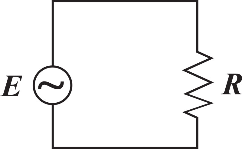
What was later to be called effective voltage was 0.707 x Vm where 0.707 is 1 / √2. The effective value is now called the root mean squared (RMS) value. I’m not going to get into the mathematical derivation of RMS. When we use a modern VOM to measure ac voltage, the meter reads volts RMS. What is important to know is that a 120-volt, 100-watt light bulb will produce the same heat and light magnitude, whether it is energized from an ac source supplying 120 volt RMS or a bank of batteries supplying 120 volts dc. AC sources in electrical diagrams are often pictured as a sine wave inside a circle (see diagram 3).
Measuring Large Magnitude Currents
There are two methods for measuring high magnitude currents in a circuit. The clip-on ammeter is the easiest method for spot-checking current in cables. The advantage of the clip-on ammeters is that the circuit does not have to be modified to measure the current. By squeezing the lever on the side of the ammeter, the jaws open. We place the jaws around the cable and then release the lever. If the jaws do not close completely, the meter will not measure the current accurately. Note the size of the window created by the jaws when purchasing a clip-on ammeter. To measure the current in large conductor cables or small cables with thick insulation will require a large window ammeter.
Current Transformers
The other method is to use a current transformer, often referred to as a CT. A current transformer looks like a large donut. The current transformer transforms high currents to low currents. The circuit in which the current is to be measured must be routed through the donut hole of the CT. There is a pair of terminals on top of the CT. These are the secondary terminals. A low current, usually 0‒5-amp ammeter, must be connected to these terminals.
The large number painted on the side of the CT is part of the CT ratio. The nameplate on the side of the CT gives the ratio for the CT. A CT with a ratio of 400 to 5 means that when 400 amps are flowing in the conductor that passes through the CT donut hole, 5 amps will pass through the secondary terminals of the CT. In the case of a 400 to 5 amp (400:5) CT, the manufacturer will paint “400” on the side of the CT. 600-volt insulated CTs are available in ratios up to 6000:5. Some CTs are available in dual ratio.
CT Shorting Bar
When you receive a CT from the manufacturer, you will find a shorting bar connecting the secondary terminals of the CT together. The bar should be removed only after the low current ammeter is connected to the terminals. Some shorting bars do not have to be removed. They can be rotated 90 degrees so that they are no longer shorting the terminals. The circuit in which a CT is wired should never be energized without the low current ammeter connected to the CT secondary terminals or the shorting bar in place. This is a safety issue! The CT can produce a high voltage on the secondary terminals if this rule is not followed.
CT Rating Factor
CT rating factor lets us know the maximum current the CT can handle. For some CTs, the maximum current is the higher number of the ratio. For those CTs, the rating factor is 1. The General Electric JAKO 400:5-amp CT has a rating factor of 4. The maximum current the CT can handle is 4 x 400 =1600 amps. Note that if you want to measure currents up to 1600 amps with this CT, the low current meter you connect to the secondary terminals of the CT must be capable of measuring current up to 4 x 5 = 20 amps.
Conductors
Most of my training in college was in electronics. When I graduated in 1971, most electronics companies were not hiring, so I took a job with the local electric utility until I could find a job in electronics. Thirty-three years later, I’m still with the utility. I have become accustomed to referring to bare wire as wire and insulated wire as cable over the years working for an electric utility. In general, most of our aerial or overhead construction involves wire, and most of our underground construction involves cable. These are the definitions that are commonly used in many electric utilities around the country. Unfortunately, the published definitions for wire, cable, and conductor vary with the source.
The definitions in the National Electrical Code (NEC) are different from those in the National Electrical Safety Code (NESC), which are also very different from slang some industries use. To reduce confusion, I recommend that if you are dealing with the NEC requirements, use the terms as defined in the NEC. Likewise, with the NESC or other industry standards. Be aware that there are differences. Since most of the readers of this series are familiar with the NEC, I will try to use the NEC terms and definitions in this segment.
While working for an electric utility, it didn’t take me long to realize that the main difference between electronics and electric power is a few zeroes. Electronic equipment usually deals with very small currents and voltages, milliamps, and millivolts. One milliamp is 0.001 amp. Electric power distribution equipment usually deals with high currents and voltages, kilo-amps, and kilovolts. One kilovolt is 1000 volts. The same is true for conductor sizes relative to electronics and electric power. Since the currents in electronic equipment are small, the conductors are usually small, 14 AWG to 24 AWG. Since the currents in electric power supply facilities are large, the conductors are usually large, from #4/0 AWG to 2000 kcmil.
Conductor area
The current-carrying capacity or ampacity of a conductor is directly proportional to the conducting material’s cross-sectional area. We usually measure the area in square inches, or square feet, or square yards, etc. In the late 1800s, the U.S. electric industry standardized on using circular mils for measuring the cross-sectional area of conductors. A circular mil is the area of a circle with a diameter of one mil (0.001 inch). The abbreviation for circular mils is cmil. There are 1,273,200 circular mils in one square inch. For conductors having a cross-sectional area smaller than or equal to 211,600 circular mils, the industry elected to adopt the Brown and Sharpe wire gage designation of 1857, what we now call American Wire Gage (AWG). The area of large conductors is often designated in kcmil (thousand circular mils) rather than cmil. For example, the cross-sectional area of 4/0 AWG is 211,200 cmil or 211.2 kcmil. Before 1972, the abbreviation for thousand circular mils was MCM.
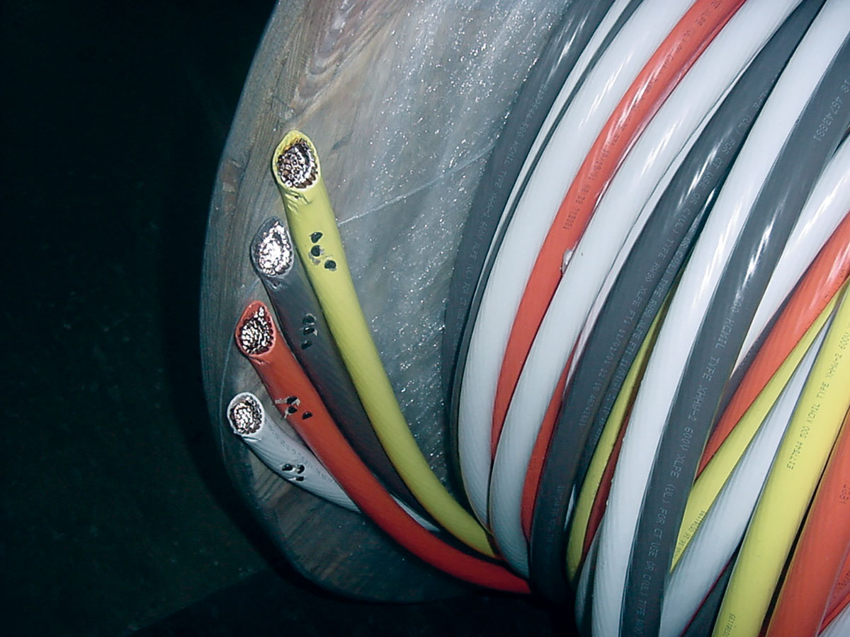
Stranding
The conductor most commonly used in houses for receptacle circuit wiring is two-conductor 14 AWG copper with the ground. The phase and neutral conductors are insulated conductors. The ground conductor is bare. Each conductor is a single solid wire. The cross-sectional area of the 14 AWG solid wire is 4,110 cmil. The 14 AWG power cord on a circular saw is very different.
On the circular saw cord, each conductor is made up of numerous small wires or strands all twisted together. This is often referred to as multiple strand conductor. The manufacturer uses multiple strands because multiple strand conductors are flexible and can be flexed hundreds of times before breaking.
A single strand conductor is usually used for installation where the conductor is not subject to flexing. If you measure the diameter of each strand of the saw cord, calculate the cross-sectional area of the strand, and multiply it times the number of strands, you will find the cross-sectional area is 4,110 cmil. I cut open the power cord of an old electric drill.
The cord was not marked as to the wire size. Using a micrometer, I measured the diameter of one of the strands. The diameter was 0.010” or 10 mils. The area of that strand is the diameter squared times p divided by 4 (p is 3.14159). The area of each strand is 0.000078539 square inches or 100 cmils. To convert square inches to cmil we multiply by 1,273,200. If we then multiply the area by the number of strands (24), we find the total cross-sectional area of the conductor is 2,400 cmil, just short of 16 AWG (2,580 cmil). 17 AWG is 2,050 cmil. It doesn’t matter if the conductor is 17 AWG single strand or 17 AWG 24 strand; the cross-sectional area is the same. With multi-strand conductors, the only way to positively identify the wire size is to use a micrometer to measure the diameter of the strands, count the number of strands, and work through the calculation. I have found that the marking on the jacket isn’t always correct.
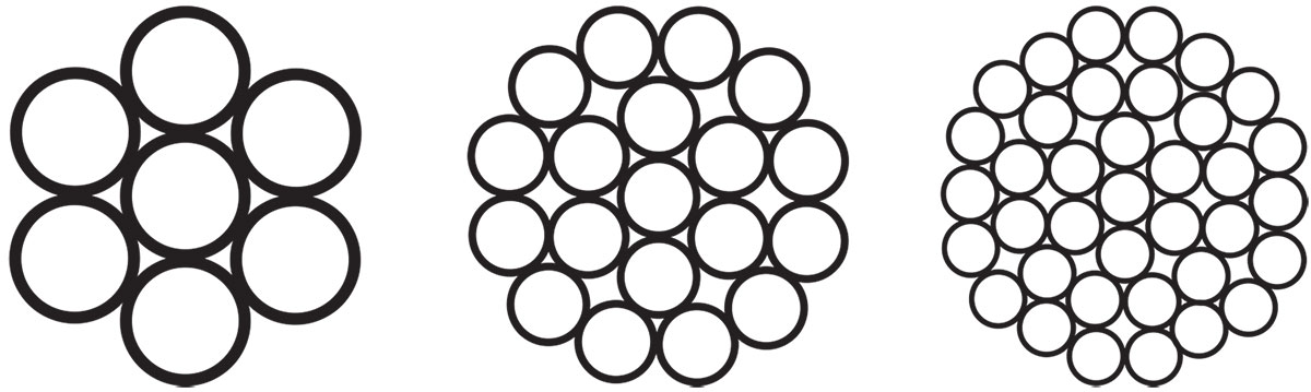
Number of strands
Conductor manufacturers make conductors in a wide variety of stranding. A few examples of stranding are shown in diagram 4.
Compressed and compact conductors
Insulated conductors are often compressed or compacted to reduce the diameter. To create compressed or compact conductors, the manufacturer draws the full strand conductors through a series of funnel-shaped dies to reduce the diameter. Full strand conductors have air space between the strands. The compression process squishes the air space out, thus reducing the diameter without reducing the cross-sectional area of the conductor.
An example of a compact conductor is shown in diagram 5. Note that the following compression, the strands are no longer round. The diameter of compressed conductors is reduced by approximately three percent. The diameter of compact conductors is reduced by approximately nine percent. If you elect to purchase compressed or compact conductors, the compression connectors that are designed to fit full strand conductors may not work on compressed or compact conductors. Compact conductors are almost as small as solid conductors. Check with the connector manufacturer before purchasing the connectors (see diagram 5).

Alloys and temper
Conductor manufacturers use many different alloys of aluminum to make aluminum conductors. The alloy of a metal defines what elements and what proportions of elements are used to make the metal. The alloy is like a recipe for the metal. Alloys are identified by number. The temper of a wire defines how the wire is thermally treated after it is manufactured. If you have ever seen a blacksmith making something out of iron, you might have noticed the blacksmith putting the item into a bucket of water while the item is still very hot. By cooling the item very quickly, the metal becomes very hard and brittle. Drill bits and other tools are tempered in this manner. Items that are cooled slowly stay soft and easy to bend.
The temper of copper wire is identified by three terms, hard drawn, medium-hard drawn and soft drawn. Copper wire that is cooled quickly to make it hard is referred to as hard drawn (HD). If copper wire is cooled slowly to make it soft and easy to bend, it is referred to as soft drawn (SD).
The temper of aluminum is usually identified by a combination of letters and numbers. For example, 1350-H19, 1350 is the aluminum alloy, H19 is the temper. This aluminum is commonly used to make what the industry calls all aluminum conductor (AAC). 6201-T81, 6201 is the aluminum alloy, T81 is the temper. This is a high strength aluminum alloy commonly used to make what the industry calls all aluminum alloy conductor (AAAC). The resistance, strength, and flexibility of the conductor are a function of the alloy, temper, and stranding.
Composite conductors
Composite conductors are conductors made up of strands of different alloys or materials. One example is the use of 1350-H19 aluminum and 6201-T81 high strength aluminum alloy. This conductor is called aluminum conductor alloy reinforced (ACAR). Some common stranding for ACAR is four strands of 1350 and three strands of 6201 or 15 strands of 1350 and four strands of 6201. Another example of composite conductors is the use of 1350-H19 aluminum and steel. This conductor is called aluminum conductor steel reinforced (ACSR). Some common stranding of ACSR is six strands of aluminum around one strand of steel or twelve strands of aluminum around seven strands of steel. Note that the cross-sectional area of aluminum in a 4/0 AWG ACSR conductor is the same as the cross-sectional area of the aluminum in a 4/0 AWG AAC conductor. That is why the diameter of an ACSR conductor is much greater than the same wire size AAC conductor. This is particularly important when ordering connectors. Some connectors designed to work on AAC conductors will not fit on the same conductor size ACSR conductors.
Code words
As you can see, if we consider the number of standard conductor sizes, the number of different stranding options, the variations in alloy, temper, insulation, and composite conductors, there are hundreds of different conductors available from the manufacturers. Rather than trying to identify each conductor with a lengthy description, the conductor manufacturers decided to assign code words to each conductor. Some of the code words are plant names and animal names. Some are just common words like Razor, Fly, and Vienna. It is so much easier to call up a supplier and ask for 10,000 feet of Celtic, rather than asking for aerial quadruplex consisting of 3-1C, 2/0 AWG, 7 strand, AAC phase with 60 mils of PE Insulation, 1-1C, 123.3 kcmil (1350 equivalent 1/0 AWG), 7 strand, 6201-T81 AAAC, bare neutral. The index for aluminum aerial conductors is published in Code Words for Overhead Aluminum Electrical Conductors. The index for aluminum underground conductors is published in Code Words for Underground Distribution Cables. The Aluminum Association publishes both standards.
If you want to learn more about aluminum conductors, I suggest you consult the Aluminum Electrical Conductor Handbook, a publication of the Aluminum Association.
Electrical resistance
Electrical resistance is not the only property of materials that resists the flow of current. Let us consider an experiment. Let’s purchase a 12,000-foot spool of insulated 20 AWG copper wire commonly used as communications wire and pull the wire off the spool, laying it out on the ground.
If we take the two ends and connect them to a male electrical plug and plug it into a 120 V AC source, we would expect the current magnitude that would flow in the wire to be equal to the source voltage divided by the wire’s resistance.
Since the resistance of 20 AWG copper wire is 10.1 W / 1000 ft at a temperature of 20°C, then 12,000 feet would have a resistance 12 x 10.1 or 121.2 W. From Ohm’s law, the current we would expect to see would be the voltage divided by the resistance, 120 / 121.2 = 0.9900 amperes. If we take the same wire and wrap it tightly around a 4-inch diameter solid rod of iron and then energize it from the 120-volt source, as before, we would find that the current is considerably less.
If the current is less, then the resistance must have increased. If the current is now 0.7682 amperes, the resistance must now be equal to the voltage divided by the current or 120 / 0.7682 = 156.21 W. How did the resistance increase from 121.2 to 156.21? It didn’t. We introduced another form of resistance to current flow into the circuit by wrapping the wire around the iron rod.
This second form is called inductive reactance. Inductive reactance is created any time we wrap wire in a coil. The current in the coiled wire creates a magnetic field around the coil. The inductive reactance is particularly high when the space inside the coil is filled with iron.
Electrical resistance in a conductor resists the flow of current by generating heat. Inductive reactance resists the flow of current by generating a magnetic field. The symbol we use in calculations to represent inductive reactance is XL. The unit of measure is the same as for electrical resistance, the ohm symbolized by W.
Impedance
In our voltage-drop calculations we performed as part of this series of articles, to calculate the current in the circuit, we divided the source voltage by the total resistance in the circuit. The total resistance in the circuit was the sum of the resistance of each element of the circuit, the service wire, the wire within the house, the extension cord, and the load. Resistance elements that are in series can be added to determine the total resistance.
When we deal with resistance and inductive reactance in the same circuit, the current in the circuit is the source voltage divided by the total impedance. Impedance is used in place of total resistance because what impedes the flow of current is a combination of resistance and inductive reactance. The term impedance is also used because resistance and inductive reactance cannot be added together.
For calculation purposes, the symbol for impedance is Z. To calculate the total impedance, we have to refer to what we call the impedance triangle. Resistance forms one side of the triangle, inductive reactance forms the other side of the triangle, and the total impedance is the hypotenuse.
The Pythagorean theorem covers the relationship between resistance, inductive reactance, and impedance; the square of the hypotenuse is equal to the sum of the squares of the other two sides. Z2 = R2 + XL2 If we solve for Z, we get:
Z = square root (R2 + XL2)
In our experiment, we found the impedance of the 12,000 feet of wire wrapped around the iron rod is equal to the source voltage divided by the current, 120 / 0.7682 = 156.21 W. Since the resistance of the wire is 121.2 W, and the total impedance of the wire is 156.21 W, the inductive reactance must be:
XL = square root (Z2 – R2)
XL = 98.54 W
Electric Motors
In general, the amount of power consumed by an electric motor is a function of the motor’s rated horsepower and how much mechanical load is placed on the motor. A motor with 100 percent efficiency would draw 746 watts of power for every horsepower of mechanical load placed on the motor. A motor with a more realistic efficiency of 80 percent would draw almost 900 watts of power for every horsepower of mechanical load placed on it. When motors run without load, they draw anywhere from 30% to 70% of their full load power.
When motors are first energized, some draw several times their full load power in the form of a current surge until the motor is up to speed. For example, my hand-held circular saw draws 22 amps for about a second when it is first turned on. After the initial surge of current, it draws 9 amps. When I’m cutting through a 4 by 4 of treated lumber, it draws 13 amps.
In general, electric motors have high levels of inductive reactance because the magnetic field is a very important part of motors. When my saw is cutting through the 4 by 4, the resistance of the saw is 7.384 W and the inductive reactance 5.538 W.
The total impedance is:
Z = square root (R2 + XL2)
Z = 9.23 W
Power
When we looked at conductors and loads with little or no inductive reactance, we only considered the resistance. We calculated the power consumed by the resistance by multiplying the voltage across the resistance times the current flowing through the resistance. Now that we are looking at a load that has both resistance and inductive reactance, we have to consider other forms of power. The power associated with the heat generated by current flowing through a resistance is called real power. It is calculated as we did before by multiplying the voltage across the resistance times the current flowing through the resistance.
The symbol for real power is P.
The unit of measure is the watt. The abbreviation for watt is W.
The power associated with inductive reactance, which maintains the magnetic field within the motor, is called reactive power. The symbol for reactive power is Q.
The unit of measure is var. There is no abbreviation.
The combination of real power and reactive power is called apparent power. The symbol for apparent power is S. The unit of measure is volt-amperes. The abbreviation is VA. To calculate the apparent power, we have to refer to what we call the power triangle. Real power forms one side of the triangle, reactive power forms the other side of the triangle, and the apparent power is the hypotenuse. The Pythagorean theorem covers the relationship between real power, reactive power, and apparent power; the square of the hypotenuse is equal to the sum of the squares of the other two sides. S2 = P2 + Q2. If we solve for S, we get:
S = square root (P2 + Q2)
The apparent power can also be calculated by multiplying the voltage times the current. For my saw, the apparent power is 120 x 13 = 1560 VA. The real power is I2 x R or 13 x 13 x 7.384 = 1248 W. The reactive power is I2 x XL or 13 x 13 x 5.538 = 935.9 var. The term power factor is commonly used to measure how much inductive reactance is in a load. Power factor is abbreviated PF and is calculated by dividing the real power by the apparent power. For my saw, the PF is 1248 / 1560 = 0.8, commonly referred to as 80% power factor. Another way of calculating PF is to divide the load resistance by the load impedance. For my saw, the PF is 7.384 / 9.23 = 0.80 or 80%.
Aught is a Middle English word meaning “a cipher; zero.” It is pronounced “ôt.”
Reprinted from IAEI Magazine. Author is David Young, “Basic Electricity Series,” from September/October 2004 through January/February 2006.