
Establishing an Electrically Safe Work Condition (ESWC) is essential for a safe working environment. NFPA 70E Article 120, Establishing an Electrically Safe Work Condition, provides the lockout and tagout requirements necessary to provide an electrically safe work environment for the employee. It differs from the OSHA requirements in that it does not distinguish between general industry and construction, nor does it specifically speak to employees that are performing servicing or maintenance of machines and equipment. Historically, lockout and tagout requirements were concerned with protecting electrical workers by controlling shock hazards. As the realization of potential hazards due to arc flash events became more predominant in the mid-nineties, the Committee on Electrical Safety Requirements for Employee Workplaces, NFPA 70E, introduced the concept of the Electrically Safe Working Condition.
Section 130.2 of NFPA 70E requires that energized electrical conductors and circuit parts that are operating at or over 50 volts be put into an electrically safe working condition if: (1) the employee is working within the limited approach boundary, or, (2) the employee is interacting with equipment where circuit conductors or parts are not exposed, but an increased likelihood of injury from exposure to arc flash hazard exists.
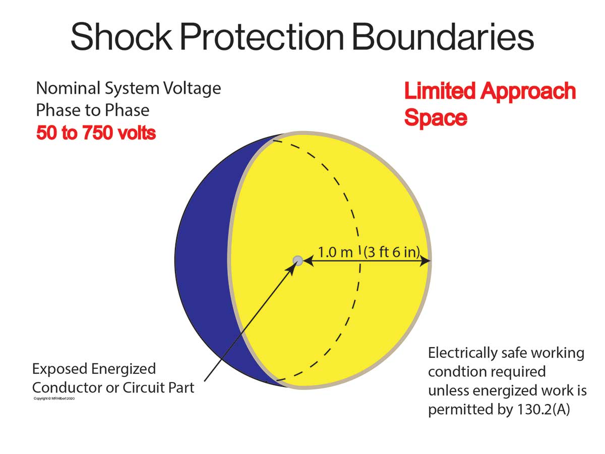
Limited approach boundary is defined in Article 100 of NFPA 70E as “an approach limit at a distance from an exposed energized electrical conductor or circuit part within which a shock hazard exists.” Therefore, in order to have a limited approach boundary, the cover(s) would have to be removed or the door(s) open, and there would have to be exposed live electrical conductors or circuit parts. In accordance with Table 130.4(d), for systems operating at 50 volts to 750 volts ac, the limited approach boundary from fixed circuit parts is 3 ft. 6 in. So, the main rule would be to place the equipment in an electrically safe working condition if the worker was going to be in the limited approach space (figure 1) unless energized work was justified per 130.4(A).
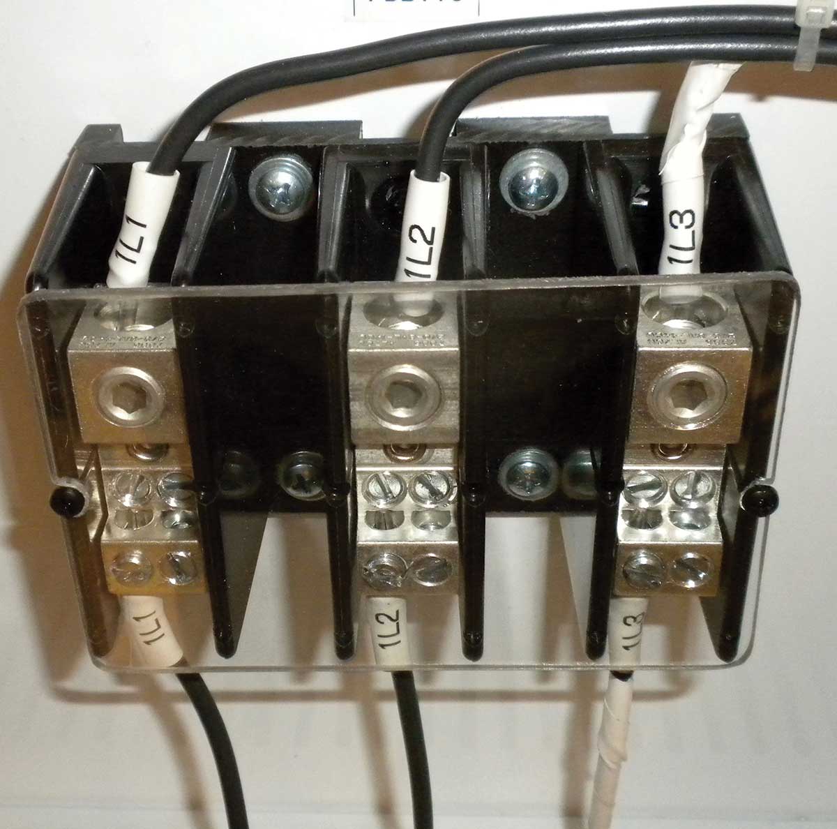
The term exposed is defined in NFPA 70E as “Capable of being inadvertently touched or approached nearer than a safe distance by a person. It is applied to electrical conductors or circuit parts that are not suitably guarded, isolated, or insulated,” which are also defined terms. So out of the gate, the definition speaks to “inadvertent touch or approach.” If the intent is to make contact, then it is not inadvertent. Quite often, electrical parts have “finger-safe terminals” or are guarded by a barrier (see photo 1). Either of these conditions would prevent inadvertent contact, so the parts would not be considered “exposed.” The term “ isolated” is clear as it is generally applied to something that is elevated, such as a gang operated switch at the top of a pole. The term that is often misunderstood is “suitably insulated.”
Conductors that are insulated can provide indirect protection as, by definition, the insulation is intended to “separate them from other conductive surfaces by a dielectric.” However, the insulation on conductors is not intended to protect from direct contact. An arc flash hazard can exist with or without exposed live parts. For example, electrical equipment that is not maintained or otherwise in generally poor condition can present an increased likelihood of injury from an exposure to an arc flash hazard when being operated.
Establishing an electrically safe work condition (ESWC) is a process. ESWC is defined as “a state in which an electrical conductor or circuit part has been disconnected from energized parts, locked/tagged in accordance with established standards, tested to verify the absence of voltage, and, if necessary, temporarily grounded for personnel protection.” The employer is required to establish, document, and implement a lockout/tagout program that specifies the lockout/tagout procedures for safeguarding employees from exposure to electrical hazards. The lockout/tagout program must be applicable to the experience and training of the workers and the workplace conditions and be applied to all fixed, permanently installed equipment, temporarily installed or portable equipment. Although not defined in NFPA 70E, OSHA identifies “fixed equipment” as equipment that is fastened in place or connected to permanent wiring methods.
The employer is responsible for providing the equipment necessary to execute lockout/tagout (LOTO) procedures, the lockout/tagout training, auditing of the lockout/tagout program, and auditing the lockout/tagout procedures. The employee is required to comply with the safety-related work practices and procedures provided by the employer.
The boundaries of the ESWC must be defined, and all exposed conductors or circuit parts tested. Establishing an ESWC complies with the traditional “lockout or tagout” but is more. It not only can protect those performing servicing or maintenance on the machine or equipment from electrical hazards, but it can also be used to protect those working in the immediate vicinity as well by providing a safe zone or area around a machine or electrical equipment being worked on. For example, if a group of carpenters were building a wall near a machine that was shut down for servicing or maintenance, they would not be required to have a lock on the lockbox or isolating device as they are not working on the machine. However, their supervisor could have a personal lock on the lockbox or isolating device as a means of protecting the carpenters building the wall.
Testing for the absence of voltage at the source of supply to the machine and at the work location on the machine would establish ESWC boundaries (safe work area) between the two points provided that all exposed conductors or circuit parts between the locations are tested. If an absence of voltage test (AVT) is performed at the source, then a test before you touch would be required at the work locations. Of course, the shock and arc flash risk assessments will determine what PPE is necessary to perform the voltage tests.
Hazardous Energy Control Procedures
There are two forms of hazardous energy control procedures permitted in NFPA 70E. They are the simple lockout/tagout and the complex lockout/tagout.
Simple lockout or tagout procedures only involve one set of conductors or circuit parts being de-energized. These procedures that are often known as “single source LOTOs” in the industry are not limited to just one qualified person, but each worker is responsible for his or her own lockout. Single source LOTO procedures are not required to be written for each application so they can be performed under the employer’s general LOTO procedure requirements. Whether the procedure is simple or complex, it is all about a worker having exclusive control of the hazard. Therefore, any individual that working on the equipment being serviced or maintained must have exclusive control of the hazard. This is generally accomplished by affixing a personal lock to the isolating device (disconnecting means).

The only exception to affixing a lock to the isolating device for the equipment being serviced or maintained, since the removal of the “individual lockout procedure” from NFPA 70E, is for cord- and plug-connected equipment where the exposure to the hazards or unexpected energization of the equipment is controlled by unplugging the equipment and the individual performing the servicing or maintenance maintains exclusive control of the plug.
The complex lockout or tagout procedures are more comprehensive procedures. Complex LOTO procedures can involve multiple sources, multiple trades, and when the job or task will continue for more than one shift. The complex or group lockout or tagout procedure is often described as a “permitted lockout or tagout” as it is required to have a written procedure for each application and many employers require a “permit” for this type of lockout.
From an NFPA 70E standpoint, the complex lockout or tagout is a permitted (optional) procedure when there are multiple energy sources, crews, crafts, locations, employers or disconnecting means or there are particular sequences, or the job or task continues for more than one shift. Although the complex lockout procedure is optional in NFPA 70E, most employers make it mandatory when you have any of the stated conditions. When it comes to group or permitted lockouts or tagouts, because they are “site-specific,” there are as many different types of procedures in the industry as there are types of locks. They are all a little different but ultimately must protect all those working under the procedure by each of those working on the equipment having exclusive control. Photo 5 is an example of a complex (group) lockout in a process facility where the operations department has control of the process. The green lock is placed by the Operations Department after the equipment has been de-energized, and the only key to it is placed in a lockbox (photo 6). Each qualified person working on the equipment being serviced or maintained has a personal lock on the lockbox thereby maintaining exclusive control of the isolating device.

Complex lockout or tagout procedures are required to have a written plan of execution that identifies the person in charge. Where employees are working under the protection of a group lockout or tagout device such as an operations lock or lockbox, the procedure vests the primary responsibility for the safety of the employees performing the job or task in an authorized employee. Therefore, the person in charge is held accountable for the safe execution of the complex procedure. They have the overall responsibility for coordinating personnel and implementing and monitoring the complex lockout or tagout. The term “authorized employee” is not defined in NFPA 70E, but OSHA’s 1910.147 defines the term as a person who locks out or tags out machines or equipment to perform servicing or maintenance on that machine or equipment. By requiring the person in charge to be an authorized employee, there is a high level of assurance that a person has been trained to and understands the procedure.
For each worker to maintain exclusive control of the hazardous energy, each authorized person must affix a personal lockout or tagout device to the group lockout device or lockbox or comparable mechanism when they begin work and must remove the device when they stop working on the machine or equipment being serviced or maintained. The person in charge would have the responsibility to ensure that each person that is working on the equipment has a lockout or tagout device in place. There can be confusion related to what “removes the lockout or tagout device when he or she stops work” means. Does it mean the end of the job or task or the end of the shift? The answer is yes! It could be either.
Quite often, when the job or task extends beyond one shift, it is desirable to have workers remove their lock from the lockbox or another comparable device when their shift ends and reinstall it when the shift begins again. In this manner, there is a reduced number of locks affixed at any given time, and if the machine or equipment being serviced or maintained needs to be temporarily reenergized for set up or troubleshooting all workers with locks affixed are present to remove them.
All complex lockout and tagout programs must identify the method of accounting for all persons who might be exposed to the electrical hazards during the course of lockout or tagout. The person in charge also has the responsibility for administrating the removal of the devices and returning the machine or equipment to service.
Process for verifying and establishing an electrically safe working condition (ESWC)
Step 1
The first step in the eight-step process of verification of an ESWC is to determine all possible sources of electrical supply to the equipment. This would include backup or alternates sources of supply and sources from equipment that has not been commissioned but is connected to a source of voltage. This is typically done using up-to-date drawings, diagrams, and identification tags. If these are not available, the onus is on the employer to find an equally effective measure.

Step 2
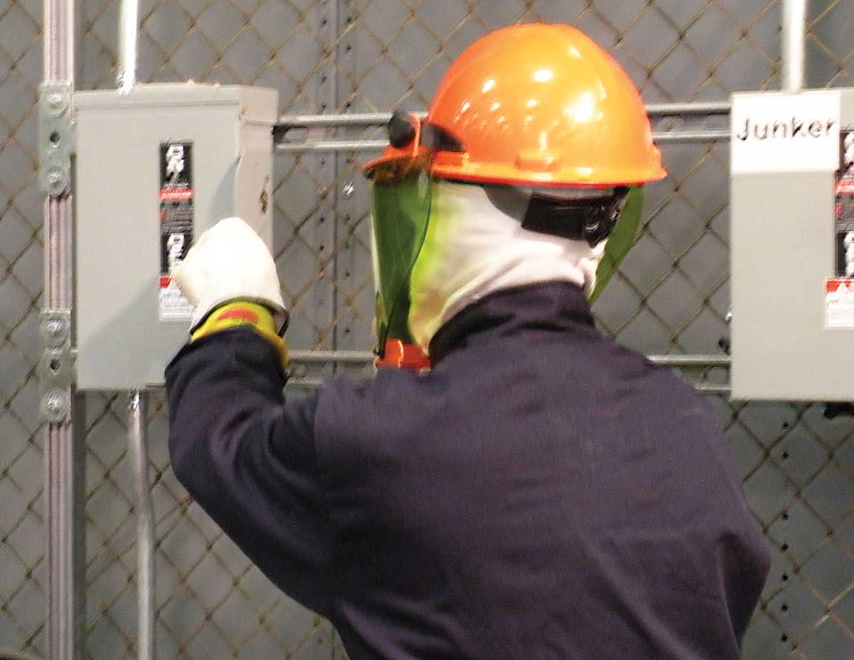
The second step is to properly interrupt the load and then open each disconnecting means (see photo 8). Proper interrupting the load is accomplished by simply turning off the equipment by the normal operating means such as pushbuttons, etc.
Step 3
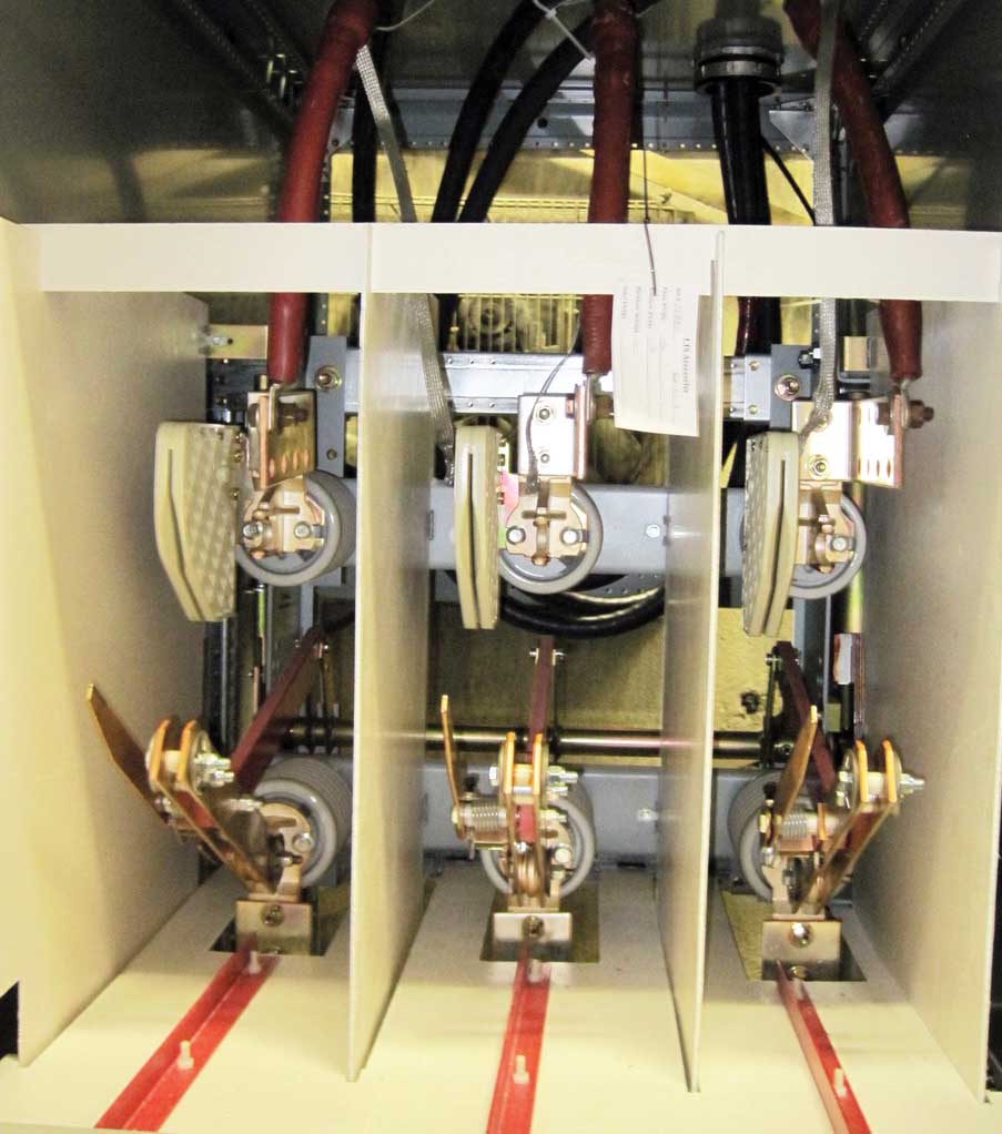
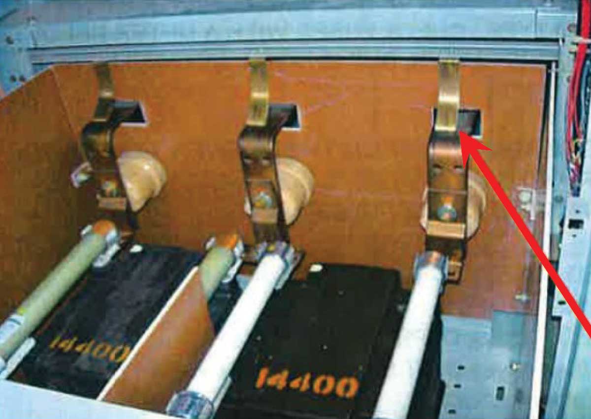
The third step in the verification process is to visually verify that all blades of the disconnecting means are open or that drawout-type circuit breakers are withdrawn to the fully disconnected position whenever possible (see photo 9). The key wording in this section is “whenever possible.” This means that it is not necessary to dismantle the equipment beyond normal applications such as the opening of doors or using viewing windows to determine if the blades are open. In some cases, such as molded case circuit breakers, there is no way to visually determine if the blades have opened.
Steps 4 and 5
The fourth and fifth steps in the verification process require the release of any stored electrical energy and the release or blocking of any stored mechanical energy, respectively. Stored electrical energy can originate from many different sources. The source could be from batteries, capacitors, long shielded cables or variable speed drives which can carry a high level of stored energy that must be dissipated prior to accessing internal connections. Where mechanical energy is a concern, the equipment must be blocked so it can’t move or the mechanical energy released, such as with spring tensions.
Step 6
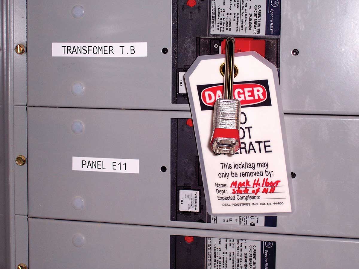
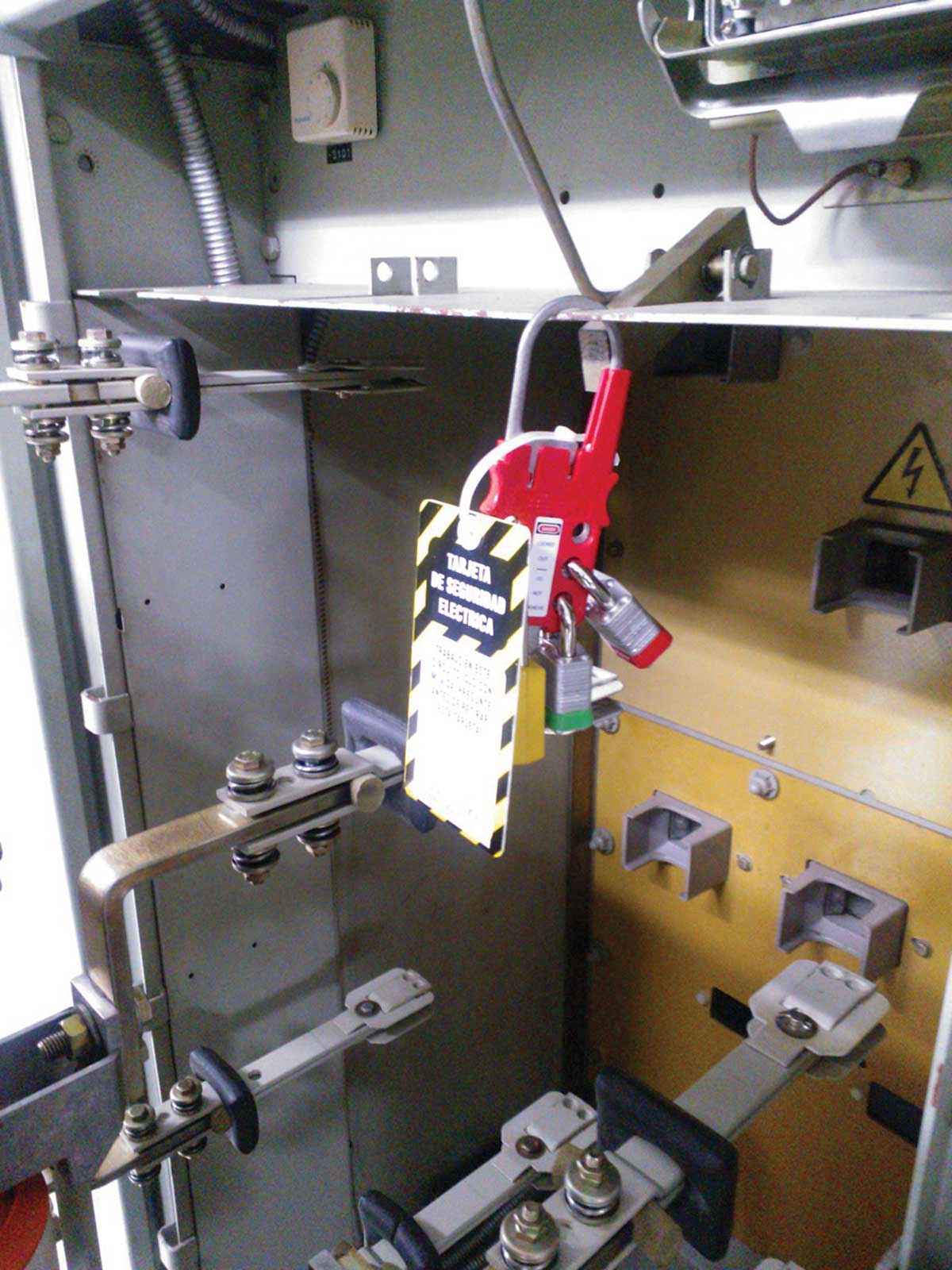
The sixth step in the verification process is for an authorized person(s) (qualified to perform lockout or tagout) to apply a lockout or tagout device in accordance with the employer’s documented and established procedure (see photo 11).

Step 7
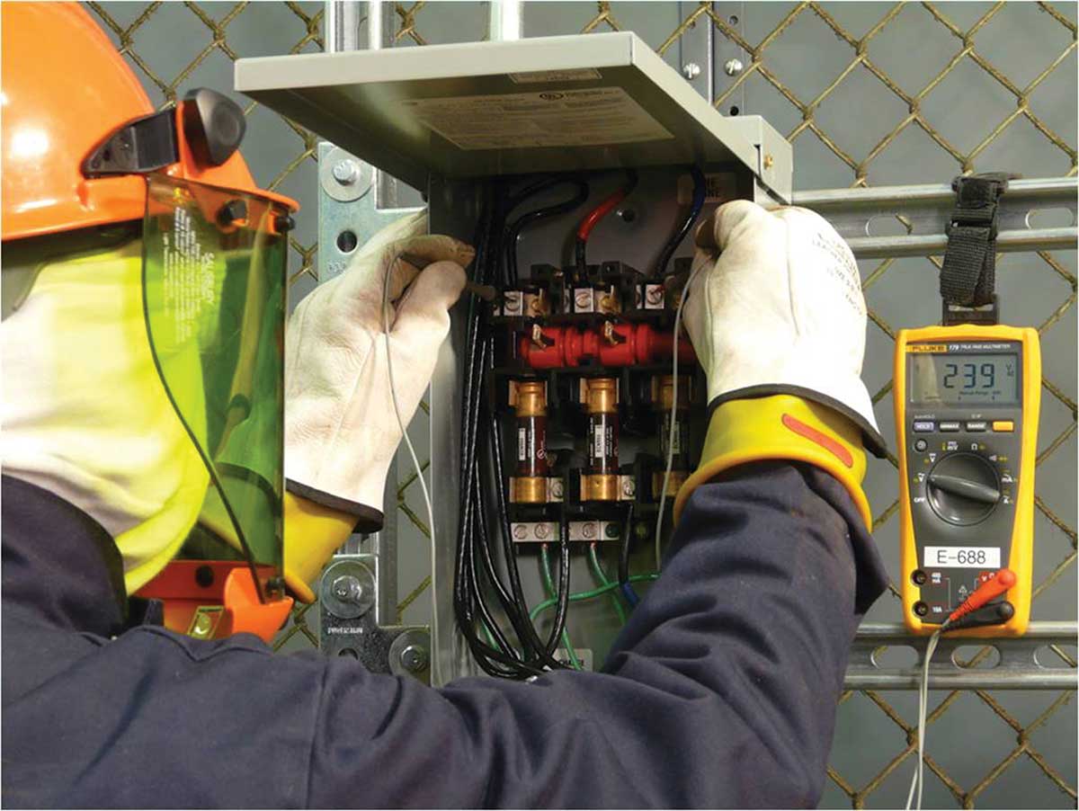
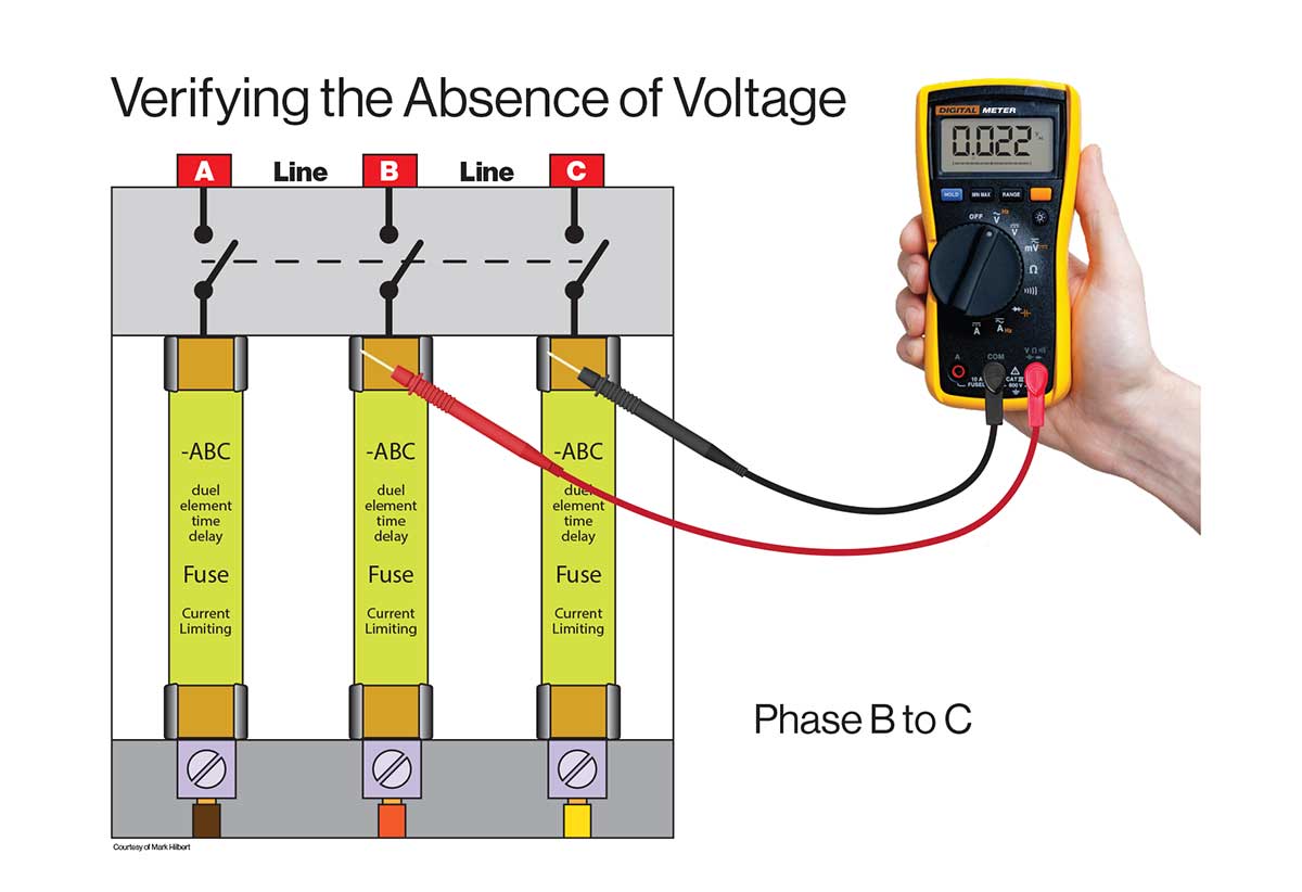
The seventh step in the process is to use an adequately rated portable test instrument to test each phase conductor or circuit part to verify it has been de-energized. This will require testing of each phase conductor or circuit part, both phase-to-phase and phase-to-ground. Before and after each test, the test instrument must be verified on any known voltage source (live-dead-live test). Each time that an absence of voltage test (AVT) is performed by a qualified person (only qualified persons can perform voltage testing), the test instrument must be verified before and after performing the phase-to-phase and phase-to-ground tests.
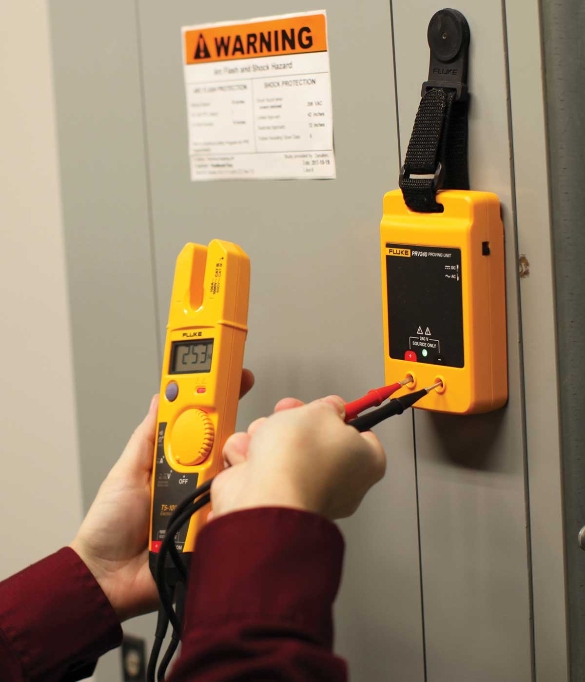
A common question about verifying the operation of the test instrument is: “does the test instrument have to be verified at the same voltage as the equipment where the AVT is being performed?” The answer is no. NFPA 70E clearly states the verification the test instrument is operating satisfactorily can be performed on “any known voltage source.” Known voltage sources could be from permanently installed equipment, as in photo 12 or from a portable means is illustrated in photo 13. Using a portable means for verifying the operation of a test instrument is extremely beneficial when working in elevated conditions such as on lift.
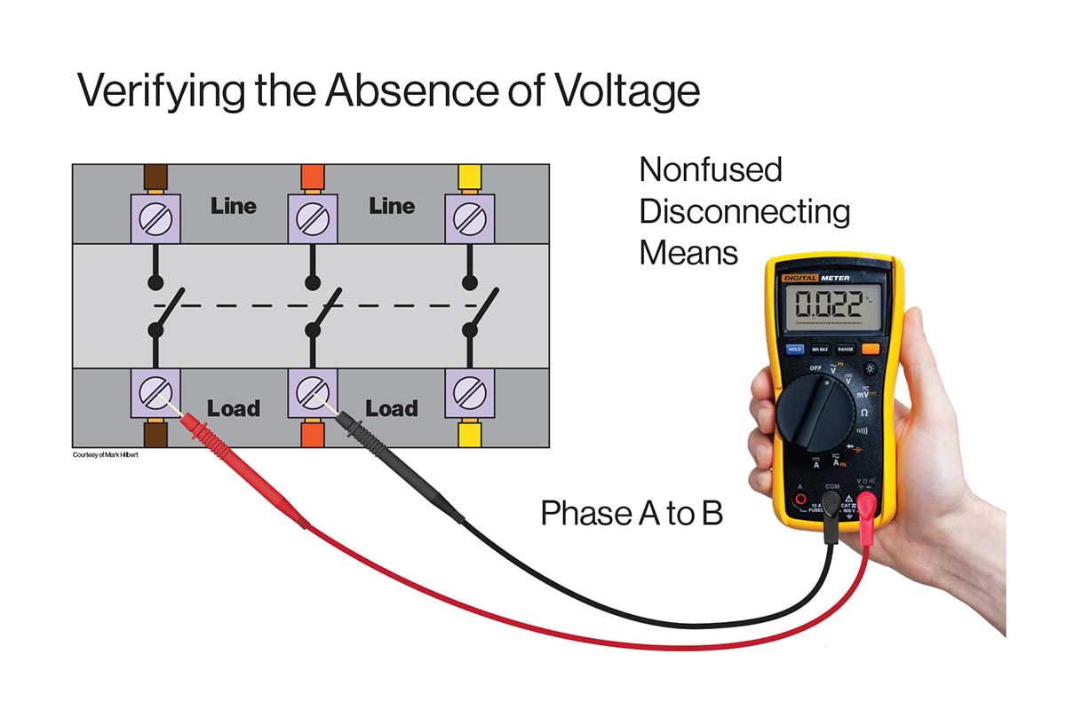
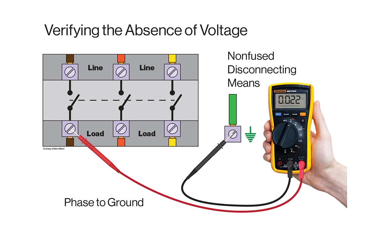
As noted above, Step 7 in the verification process requires testing each conductor or circuit part, both phase-to-phase and phase-to-ground. It is essential that both tests be performed as they “back each other up.” On the other hand, if testing on a grounded system and only a phase-to-phase test is conducted and two of the three phases were not energized because of blown fuses or faulty switching mechanisms, the test instrument may not show a presence of voltage. A phase-to-ground test here would show the presence of voltage.
Performing a phase-to-phase test may be the only valid test if the system is an ungrounded delta system. Because the “system” is not grounded, there is no connection between the equipment enclosure and the source. Therefore, performing a phase-to-ground (phase-to-enclosure) test will not likely indicate a source of voltage even if a phase conductor were still energized.
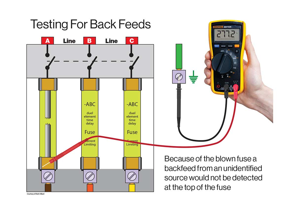
Care must be taken when performing an AVT with fused equipment. After performing the phase-to-phase and phase-to-ground tests across all phases at the load terminals of the switch (top of the fuses) as shown in figures 4 and 5, a phase-to-ground test must be performed at the load terminals of the fuses. Performing the required tests at the top of the fuses verifies all the blades of the switch have opened but may not identify a backfeed if there was a blown fuse as illustrated in figure 6.

By exception, permanently mounted testing devices are permitted for absence of voltage tests. Because verifying the absence of voltage is a hazardous task, the industry has long-sought-after alternative methods of verifying the absence of voltage that would not expose a worker to possible hazard(s). Until recently, there were no products available that were designed for the purpose, and that would perform the necessary steps. Recognizing new devices on the market, the use of permanently installed testing devices is permitted for performing an AVT. The device must be adequately rated, installed at the work location, used in accordance with the manufacturer’s instructions, the conductors and circuit parts are tested at the work location, the devices are listed and labeled for the purpose of performing an AVT, each conductor and circuit part is tested both phase-to-phase and phase-to-ground and the device is verified as operating satisfactorily on a known voltage source before and after verifying the absence of voltage.
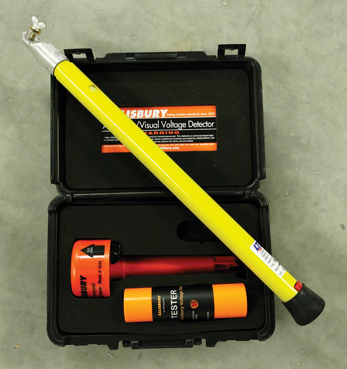
Using noncontact test instruments to verify the absence of voltage. Using noncontact test instruments to verify the absence of voltage is permitted for systems over 1000 volts. Although non-contact or proximity testers are manufactured in both low and high voltage models, they can only be used for verifying the equipment is de-energized (performing an AVT) on systems that operate over 1000 volts. With systems over 1000 volts, there are generally other safeguards that are required, such as visually verifying the blades of a pole switch are open and placement of safety grounds in addition to the performing a test for the absence of voltage. With systems over 1000 volts, the “test” does not require a phase-to-phase and phase-to-ground contact.
Low-voltage noncontact or proximity testers are reliable devices that are available as both listed and category rated devices. They cannot be used alone to perform an AVT on systems 1000 volts or less because a phase-to-phase and phase-to-ground test cannot be made. However, they can be used to verify if there is a presence of voltage before performing the AVT with a contact test instrument and, if the company policy permits, they can be used to perform an unattended test or test before you touch if the AVT was performed upstream of the location where the job or task is being performed. As with any test instrument, proper training and understanding of the device are paramount, and the device should be verified as operational before and after use. Low-voltage proximity testers are capacitive type devices that measure the field around the conductor, so they do have limitations. They may not detect voltage if the user is isolated from ground, the test point touches metal, it is used inside of a metal enclosure, or it is used with shielded cables. These devices also have a low voltage threshold of 50 to 70 volts and as the battery weakens, the threshold may increase. For these reasons, it is necessary to use a contact type test instrument for the AVT.


Step 8
The eighth step in the process would be to establish temporary protective grounding. This may be necessary when there is the possibility of induced voltages or stored electrical energy and when it could be reasonably anticipated that circuit parts being de-energized could contact other exposed energized equipment. The phase conductors and circuit parts must be grounded before touching them when these conditions exist. The main reason for applying temporary grounding is to provide protection against electric shock. Temporary protective safety grounds are often applied on medium and high voltage installations as induced voltages can occur with long runs, and there are energized conductors adjacent to those being worked on (inductive coupling). It is also common for sources of power to originate at locations such as switchyards which may not be under the exclusive control of the facility where the job or task is being performed. These systems also often run outside overhead, where higher voltage conductors could fall and reenergize de-energized lower-voltage conductors.
Of course, the absence of voltage must be verified before the application of protective grounding equipment as essentially, the installation creates a phase-to-phase and phase-to-ground faults. The placement location, sizing, and application of temporary protective grounding equipment must be identified as part of the job safety planning. Temporary protective grounding equipment must be sized to safely carry the maximum fault current for the time it takes to clear the fault and the equipment and connections made in a manner the provides a low enough impedance pathway to cause immediate operation of the overcurrent device.
Remember, establishing an electrically safe working condition is a process that must be completed in its entirety and to always: test before you touch!