Intrinsic safety is the method of protection for control and instrumentation circuits where the nominal voltage is 24 VDC or less and the current is normally less than 100 mA. The concept of intrinsic safety is to limit the voltage and current so that there is never a spark with enough energy to create an explosion. Intrinsic safety when properly used removes the ignition from the explosion triangle.
There are three components to an intrinsically safe circuit: the field device, intrinsically safe barrier and field wiring.
- Field devices known as intrinsically safe apparatus are classified as simple or complex.
- Simple apparatus, which do not need to be approved, are non-energy storing devices such as contacts, thermocouples, RTDs, LEDs and resistors.
- Complex apparatus such as transmitters, solenoids, relays and transducers may store excess energy and need to be approved by a third party.
- Contacts, transmitters and temperature sensors are the most commonly used field devices in intrinsically safe applications.
- The intrinsically safe barrier limits the current with a resistor and the voltage with a zener diode.
- Intrinsically safe circuits are designed so that they operate properly under normal conditions, but keep the energy levels below the ignition curves when a fault condition occurs.
Three components to a barrier limit current and voltage: a resistor, at least two zener diodes, and a fuse. The resistor limits the current to a specific value known as the short-circuit current(Isc). The zener diode limits the voltage to a value referred to as open-circuit voltage (Voc). The fuse will blow when the diode conducts. This interrupts the circuit, which prevents the diode from burning and allowing excess voltage to reach the hazardous area. There always are at least two zener diodes in parallel in each intrinsically safe barrier. If one diode should fail, the other will operate providing complete protection.
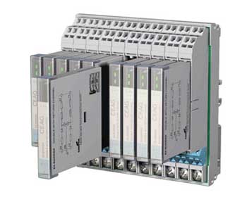
Photo 1. Cooper Crouse-Hinds offers grounded and isolated intrinsically safe barriers in addition to intrinsically safe remote I/O.
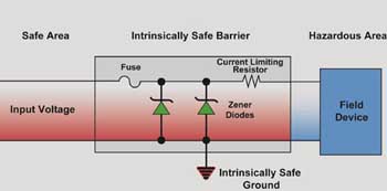
Figure 1. Barrier circuit with an intrinsically safe barrier
A simple analogy is a restriction in a water pipe with an overpressure shutoff valve. The restriction prevents too much water from flowing through the point, just like the resistor in the barrier limits current. If too much pressure builds up behind the restriction, the overpressure shutoff valve turns off all the flow in the pipe. This is similar to what the zener diode and fuse do with excess voltage. If the input voltage exceeds the allowable limit, the diode shorts the input voltage to ground and the fuse blows, shutting off electrical power to the hazardous area.
Determining Safe Energy Levels
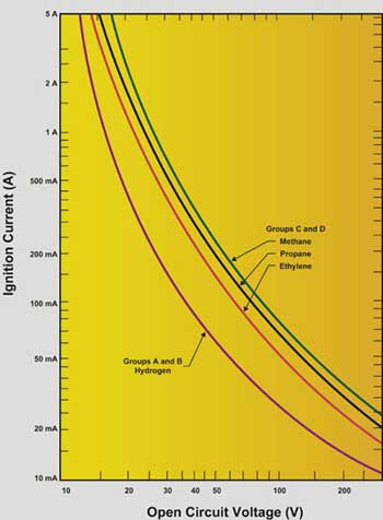
Figure 2. If the energy level of a typical thermocouple circuit were plotted on the ignition curve in figure 2, it would not be close to the ignition levels of the most volatile gases in Group A.
Voltage and current limitations are ascertained by ignition curves, as seen in figure 4. A circuit with a combination of 30 V and 150 mA would fall on the ignition level of gases in Group A. This combination of voltage and current could create a spark large enough to ignite the mixture of gases and oxygen. Intrinsically safe applications always stay below these curves where the operating level of energy is about 1 watt or less. There also are capacitance and inductance curves which must be examined in intrinsically safe circuits. [See figure 1]
Consider the ignition curves to demonstrate a point about thermocouples. A thermocouple is classified as a simple device. It will not create or store enough energy to ignite any mixture of volatile gases. If the energy level of a typical thermocouple circuit were plotted on the ignition curve in figure 2, it would not be close to the ignition levels of the most volatile gases in Group A. Is the thermocouple which is installed in a hazardous area (see figure 3) intrinsically safe? The answer is no, because a fault could occur on the recorder which could cause excess energy to reach the hazardous area, as seen in figure 4. To make sure that the circuit remains intrinsically safe, a barrier to limit the energy must be inserted (see figure 5).
Approvals—Start with the Field Device
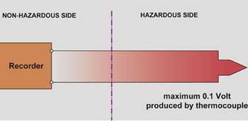
Figure 3. Is the thermocouple which is installed in a hazardous area (see figure 3) intrinsically safe? The answer is no, because a fault could occur on the recorder which could cause excess energy to reach the hazardous area, as seen in figure 4.
All intrinsically safe circuits have three components: the field device referred to as the intrinsically safe apparatus, the energy-limiting device also known as the barrier or intrinsically safe associated apparatus, and the field wiring. The design of the intrinsically safe circuit begins with the analysis of the field device. This will determine the type of barrier that can be used so that the circuit functions properly under normal operating conditions but is still safe under fault conditions.
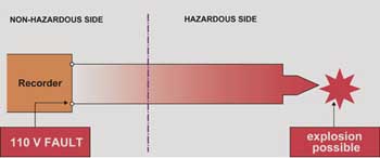
Figure 4. A fault could occur on the recorder which could cause excess energy to reach the hazardous area
An intrinsically safe apparatus (field device) is classified either as a simple or non-simple device. Simple apparatus is defined in paragraph 3.12 of the ANSI/ISA-RP12 12.6-1987 as any device which will neither generate nor store more than 1.2 volts, 0.1 amps, 25 mW or 20 µJ. Examples are simple contacts, thermocouples, RTDs, LEDs, nonincendive potentiometers and resistors. These simple devices do not need to be listed as intrinsically safe (see 504.4, Exception). If they are connected to an approved intrinsically safe apparatus (barrier), the circuit is considered intrinsically safe.
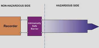
Figure 5. To make sure that the circuit remains intrinsically safe, a barrier to limit the energy must be inserted
A non-simple device can create or store levels of energy that exceed those listed above. Typical examples are transmitters, transducers, solenoid valves, and relays. When these devices are approved as intrinsically safe, under the entity concept, they have the following entity parameters: Vmax (maximum voltage allowed); Imax (maximum current allowed); Ci (internal capacitance) and Li (internal inductance).
The Vmax and Imax values are straightforward. Under a fault condition, excess voltage or current could be transferred to the intrinsically safe apparatus (field device). If the voltage or current exceeds the apparatus Vmax or Imax, the device can heat up or spark and ignite the gases in the hazardous area. The Ci and Li values describe the devices’ ability to store energy in the form of internal capacitance and internal inductance. [See photos 1, 2, and 3]
Limiting Energy to the Field Device
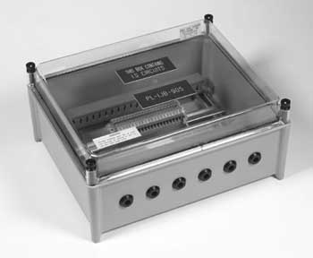
Photo 2. Terminal boxes and conduits carrying intrinsically safe circuits must be separated from all other wiring and properly labeled.
To protect the intrinsically safe apparatus in a hazardous area, an energy-limiting device (barrier) must be installed. Under normal conditions, the device allows the intrinsically safe apparatus to function properly. Under fault conditions, it protects the field circuit by preventing excess voltage and current from reaching the hazardous area. When conducting the safety analysis or inspection of the circuit, it is important to compare the entity values of the intrinsically safe apparatus against the associated apparatus. These parameters usually are found on the product or in the control-wiring diagram from the manufacturer.
Intrinsically Safe Barriers
Three types of barriers are most commonly used:
1. Zener barriers—passive devices which required grounding for safety
2. Isolation barriers—do not require grounding and contain additional electronics for isolation and signal conditioning, or
3. Ex-ia I/O—combines I/O with intrinsic safety into one package.
Grounded Zener Barriers
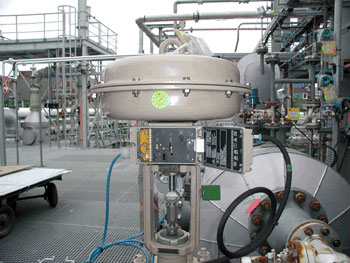
Photo 3. Intrinsically safe circuits can be worked on while live without danger of creating sparks with enough energy to cause ignition.
Grounded barriers, also referred to as zener barriers, are passive devices which contain zener diodes to limit excess voltage, resistors to limit current and fuses. These are the basic building blocks which are contained in all other intrinsically safe barriers. There is always a voltage drop across grounded barriers because of the resistors so some selection is required as well as a ground connection. This selection has been greatly simplified in recent years as manufacturers make them more application specific. Grounded barriers are also very versatile and can be applied in many other applications. If your application has less than 20 outputs or inputs and grounding is not a consideration, this may be the best solution.
DIN Rail Grounded Barriers
Advantages include:
- lowest initial cost per unit;
- very small < 1/2″ wide;
- very precise signal response;
- small power requirements; and
- versatile for “other” circuits.
Other considerations include:
- requires ground; and
- barrier resistance can influence circuit function.
Isolation Barriers
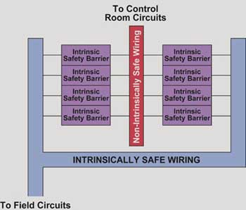
Figure 6. The intrinsically safe conductors must be separated from all other wiring by placing them in separate conduits or by a separation of a minimum of 2 inches of air space.
DIN rail isolated barriers, also referred to as transformer-isolated or galvanically-isolated barriers, are zener barriers with additional electronics to isolate and condition the signals. Adding the isolation has the advantage that an intrinsically safe-ground connection is not required. The signal conditioning of isolated barriers simplifies the selection process as each isolated barrier is manufactured for specific functions such as switching, temperature measurements or 4-20 mA readings. These isolated units are ideal for digital inputs or for OEMs where grounding may cause problems at the local installation.
Din Rail Isolated Barriers
Advantages include:
- does not require IS ground;
- loop layout and barrier selection is easier; and
- integrated signal conditioning.
Other considerations include:
- higher cost than grounded barriers;
- larger width ˜1″” wide; and
- larger power requirements.
Remove I/O Products
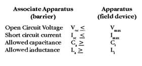
Table 1
Until recently there were limited improvements made in this industry. The latest generation of products now reduce the total installed cost by combining the intrinsically safe barriers with the I/O eliminating extra hardware. These new systems called intrinsically safe remote I/O can be mounted almost anywhere in hazardous or ordinary locations reducing the wiring and terminations. These systems were initially designed for the German Chemical industry which wanted to reduce installation costs and no longer had enough space in control rooms to house termination panels. Their reasoning was to extend the 2-wire communication lines out as far away as possible in the process area to minimize field wiring to the sensors and extra termination cabinets.
Signals to and from the hazardous area are made intrinsically safe, processed by the remote I/O electronics, and transmitted to a memory module through a communication link that is normally mounted on the backplane, which holds the electronics. These signals are updated every 5 milliseconds and stored for pickup and transport to the main control system. The intrinsically safe remote I/O system is connected to the controller by a simple 2-wire or fiber optic link to relay information back and forth.
These systems are ideal for users, who want to eliminate wiring from the control system to the I/O and can communicate via a bus system such as Modbus, Profibus, or Fieldbus.
Intrinsically Safe Remote I/O Systems
Advantages include:
- lowest installed cost (40 percent savings);
- uses digital communications for more accurate and faster readings;
- easy product selection;
- least amount of wiring;
- no ground required; and
- easiest add-on for future.
Other considerations include:
- some expertise required in “systems.”
Remember the keys to intrinsic safety are:
- it is used only on instrumentation and control circuits that operate on 24 volts or less;
- it is not used on power circuits of 30 volts and definitely not 120 volts and above;
- it is used in Division 1 and Zones 0 and 1 areas; and
- intrinsic safety barriers prevent ignition of volatile gases and dusts by limiting the voltage and current into hazardous areas.
Three solutions depend on the number of devices that need to be protected in the hazardous area ranging from simple passive devices which require grounding, isolated devices which do not need a ground, and the intrinsically safe remote I/O which eliminates hardware and field wiring.
Select the Proper Product for Your Intrinsically Safe Application
Before selecting the best protection method, examine the mix of analog and digital signals, whether a ground is available, amount of cabling required, and space in the control room. There are enough options available now to simplify the installation and reduce the system costs.
Many different products will make a sensor or instrument intrinsically safe. Many times selecting the correct product is troublesome for the first time user. For a complete explanation on how to select the proper barrier refer to the website. www:ISBARRIERS.com
Installation, Maintenance and Troubleshooting of Intrinsically Safe Circuits
Explosionproof seals are not required if a suitable mastic is used that prevents the transmission of gases. No special maintenance for intrinsically safe circuits is required.
- Intrinsically safe circuits use normal wiring practices, but care must be taken to separate and identify these circuits.
- A proper grounding system will have only one grounding point.
- There are five rules of grounding to ensure the system is safe.
- Explosionproof seals are not required.
- Intrinsically safe seals must prevent the transmission of gases.
- No special maintenance is required.
- Troubleshooting the system includes: checking that the wiring is installed correctly, the circuit is powered, the barrier resistance is not too high and the fuse is not blown.
The intrinsically safe system must be properly installed and provisions must be made to maintain and troubleshoot it. These provisions are discussed in detail in Article 504 of the National Electrical Code (NEC) and the ANSI/ISA RP 12.6-1987 Recommended Practice Installation of Intrinsically Safe Systems For Hazardous (Classified) Locations.
Wiring
Intrinsically safe circuits may be wired in the same manner as comparable circuits installed for unclassified locations with two exceptions summarized as separation and identification. These wiring practices are simple and clear; however, they often are overlooked and are the source of potential problems. The intrinsically safe conductors must be separated from all other wiring by placing them in separate conduits or by a separation of a minimum of 2 inches of air space. Within an enclosure the conductors can be separated by a grounded metal or insulated partition (see figure 6).
Barrier Installation
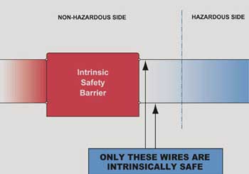
Figure 7. Conductive dust or moisture could lessen the required distance of 2 inches between intrinsically safe and non-intrinsically safe conductors
The barriers normally are installed in a dust- and moisture-free IP 54 or NEMA 4 or 12 enclosure located in the non-classified area. Only the barrier outputs are intrinsically safe. Conductive dust or moisture could lessen the required distance of 2 inches between intrinsically safe and non-intrinsically safe conductors (see figure 7). The enclosure should be as close as possible to the hazardous area to minimize cable runs and increased capacitance of the circuit. If they are installed in a hazardous area, they must be in the proper enclosure suited for that area.
Grounding
First determine if the intrinsically safe barriers used in the system are grounded or isolated. The isolated barriers normally are larger, more expensive, and do not require a ground for safety. The grounded safety barriers are smaller and less expensive, but require a ground to divert the excess energy. The main rules of grounding intrinsically safe systems are:
- The ground path must have less then 1 ohm of resistance from the furthest barrier to the main grounding electrode.
- The grounding conductor must be a minimum 12 AWG.
- All ground path connections must be secure, permanent, visible, and accessible for routine inspection.
- A separate isolated ground conductor normally is required since the normal protective ground conductor (green or yellow/green wire) may not be at the same ground potential because of the voltage drop from fault currents in other equipment.
- For installations designed to Canadian standards, the Canadian Electrical Code (Appendix F) recommends redundant grounding conductors.
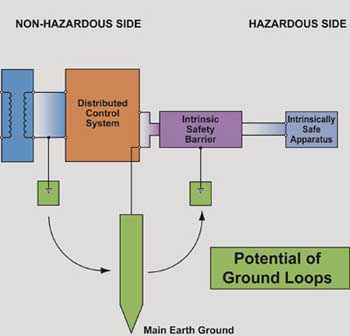
Figure 8. Figure 8 shows an improperly grounded system
A poor grounding system can influence the function of the system by creating noise on the circuit or modifying the signals. Figure 8 shows an improperly grounded system. The numerous grounding points create ground loops which can modify the signals and induce stray voltages into the intrinsically safe circuits. The correct method of grounding is shown in figure 4 where all the grounds are tied together at one single point in the system. [See figure 9]
Sealing
The requirements for sealing intrinsically safe circuits have been discussed by a panel of experts and published in “”Seals for Intrinsically Safe Circuits,”” EC&M, September 1992, pp. 48-49. The panel’s conclusion is that boundary seals are required to prevent the transmission of gases and vapors from the hazardous area to the non-hazardous area, not to prevent passage of flames from explosions. Explosionproof seals are not required as long as there is some other mechanical means of preventing the passage of gases such as positive pressure in the control room and/or application of an approved mastic at cable terminations and between the cable and raceway. Many experts generally agree that a commercially available silicon caulk is a suitable mastic which would minimize the passage of gases. This must, however, be acceptable to the authority having jurisdiction.
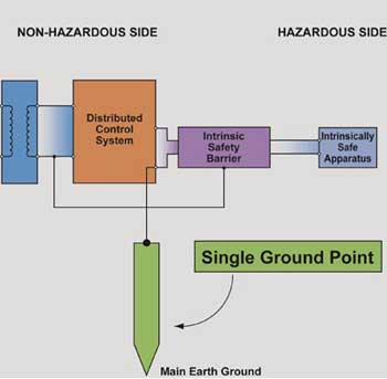
Figure 9. Correct grounded system where all the grounds are tied together at one single point in the system
When barriers are installed in explosionproof enclosures, which are located in the hazardous area, explosionproof seals are required on the enclosure (see figure 10). Since other conduits containing non-intrinsically safe conductors between the hazardous and non-hazardous areas require explosionproof seals, it is good practice to maintain consistency and install explosionproof seals on the conduits containing intrinsically safe conductors also. The exception to this would be where multi-conductor shielded cable is used. This cable may be difficult to seal in some explosionproof fittings. However, it will be necessary to seal both the cable terminations and between the cable and raceway to minimize the passage of gases, vapors, or dust.
9.5.5 Maintenance
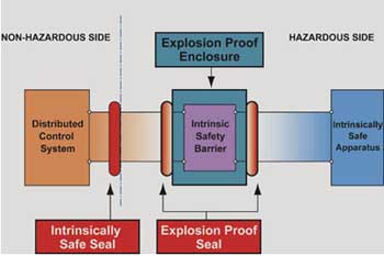
Figure 10. When barriers are installed in explosionproof enclosures, which are located in the hazardous area, explosionproof seals are required on the enclosure
No special maintenance of intrinsically safe systems is required. Once a year the barriers should be checked to ensure that the connections are tight, the ground wiring has less then one ohm of resistance, and the barriers are free from moisture and dirt. Check the panel and conduits for separation and identification of the intrinsically safe wiring. Never test the barrier with an ohmmeter or other test instrument while it is connected in the circuit (see figure 11). This bypasses the barrier and could induce voltages into the intrinsically safe wiring.
9.5.6 Troubleshooting
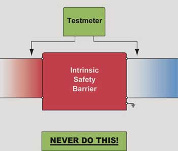
Figure 11. Never test the barrier with an ohmmeter or other test instrument while it is connected in the circuit
If the intrinsic safety circuit does not operate properly once it is completed and energized, follow these troubleshooting guidelines:
- Make sure the connections are tight.
- Check the wiring to the appropriate terminals against the control wiring diagram. A control wiring diagram is defined by the NEC as “a drawing or other document provided by the manufacturer of the intrinsically safe or associated apparatus that details the allowed interconnections between the intrinsically safe and associated apparatus.” These diagrams are easier to obtain than in the past. Make sure that one of the manufacturers provides not only diagrams which show the interconnections between the field device and barriers, but also wiring diagrams which demonstrate that the circuit functions properly and is safe by comparing the safety parameters of the field device and the barriers.
- Make sure the circuit is powered.
- Check to see if the resistance in the barrier is too high for the circuit. As stated in the previous articles in this series, circuits are analyzed for the proper loop resistance (barrier and cable) and supply voltages. If the circuit does not operate properly, check the circuit against the design in the control wiring diagram.
- Check for a blown barrier fuse, by disconnecting the barrier from the circuit and measuring the end-to-end resistance of the barrier. If the ohmmeter registers an infinite resistance, the fuse in the barrier is blown. The fuse has opened because of a fault in the circuit, so reevaluate the entire circuit before reinstalling a new barrier.
9.5.7 Barrier Replacement
If the barrier’s fuse has opened, it usually is the result of excessive voltage being applied to the barrier. This causes the diode to conduct, which results in high current in the fuse. After determining the cause of the excess voltage, the barrier must be replaced. The procedure is to disconnect the wiring from the safety barriers in the proper order of non-hazardous terminal first, hazardous terminals next, and the ground last. Cover the bare wire ends with tape, replace the barrier, and then reverse the procedure to mount the new barrier. Always install the ground first and disconnect the ground last.