In the world of electrical systems, the selection of conductors and the overcurrent protective devices (OCPDs) that protect those conductors is crucial for ensuring safe and efficient installations. Conductors are the glue for the electrical power distribution system, and the overcurrent protective devices (OCPDs) that protect them are there to ensure they perform their function with proper protection. The bottom line is that conductors connect equipment and devices so they can perform their function without damage to themselves, all while under the watchful eye of an OCPD.
This article breaks down the process of conductor selection and protection, providing the fundamental critical factors and techniques to avoid common pitfalls.
The Basics – Establishing the Process
It is quite possible to establish a process that, when followed, will reduce the likelihood of pitfalls that lead many to make mistakes. As a young engineer, I struggled with this topic because, quite frankly, the electrical code is not easy to follow. To me, this was one of the great mysteries of the electrical industry. My frustration was real and what I didn’t realize was that I was not alone. The electrical code language does not make the topic of ampacity nor the proper selection of an OCPD easy. This challenge was real 35 years ago and is real today. What I hope to do in this article is to add clarity on the proper selection of both the conductor and the OCPD to serve a known load. I plan to focus this on branch circuits and feeders. Future articles will dig deeper into service applications, motor applications and small conductors. We will navigate the electrical code to determine ampacity and establish the key components of a circuit that align with the electrical code and with product standards. Let’s take what is almost pure madness and make it clear.
The first thing we need to do is to establish a fundamental separation between the ampacity of the conductor and the limitation placed upon the circuit by the equipment at each end of the conductor. These are two separate yet interrelated worlds. The conductor has capabilities we know as ampacity and must be protected to ensure it performs its function without damage to itself. Equipment also has capabilities such as the maximum current that the equipment or termination can carry based on the conductor size terminated and the temperature rating of the equipment. These two electrical components must be understood and addressed separately when selecting a conductor and OCPD that works. It is often the case that either the equipment or the conductor is the limiting factor for proper protection. Once you know your boundaries, proper selection of conductor and OCPD can be made.
Once we separate these two areas of consideration, the requirements begin to make sense and selection becomes logical and hence easier.
Load Current
One of the first steps necessary in determining the appropriate conductor size for any electrical application is identifying the load current to be served. It is equally important to distinguish between continuous and non-continuous loads. A continuous load is defined as one where the maximum current is expected to continue for three hours or more. This distinction is particularly relevant to the equipment connected to the conductor, rather than the conductor itself. Keep in mind, too, that a device such as a motor can never be a continuous load even if the motor runs for 3 hours or more. The reason is because of the definition of continuous load, which includes the words maximum current, as the maximum current for a motor would be the locked rotor current, which would not persist for 3 hours or more.
The determination of the load current can be based on the specific load being served or on Article 220 load calculation methods. The bottom line is that the current that the conductor must deliver will be required before we begin the process of selecting a conductor and determining proper overcurrent protection.
Conductors
The conductors addressed in this article are insulated—encased within a material of recognized composition and thickness that meets the electrical code requirements for electrical insulation. While this insulation protects against physical and electrical hazards, it can only tolerate a limited amount of heat. When current flows through a conductor, electrical resistance generates heat, and if the heat is not properly managed, the insulation can degrade or fail. This relationship between current and heat leads to the concept of ampacity—the ability of a conductor to carry current continuously under its conditions of use without exceeding its temperature rating or damaging itself.
Conductors, when properly selected according to their conditions of use, can safely carry current indefinitely without degradation. The ampacity values provided in Table 310.16 of the electrical code are based on specific conditions of use: no more than three current-carrying conductors in a raceway or cable, and an ambient temperature of 86°F (30°C). Provided these conditions are met, the current values of the table can be sustained continuously by the conductors, as the insulation of the conductors is rated to handle such loads without sustaining damage.
It’s critical that we understand ampacity and the conditions of use to properly apply a conductor when those conditions of use do not equate to that which is found for example in Table 310.16. Two primary factors influence a conductor’s ampacity. The first is the ambient temperature surrounding the conductor; higher ambient temperatures reduce the conductor’s ability to shed heat, causing its temperature to rise more quickly. The second factor is the number of current-carrying conductors installed together in a raceway or cable; additional conductors generate more heat in a confined space, further increasing conductor temperature. Both factors directly affect the insulation’s ability to withstand heat and must be considered in every installation.
The electrical code addresses these considerations in several key locations. Table 310.16 provides conductor ampacity values based on specific conditions of use—specifically, not more than three current-carrying conductors in a raceway or cable, and an ambient temperature of 86°F (see Note 1 to Table 310.16). When installation conditions differ from these assumptions, the ampacity values in Table 310.16 must be adjusted using correction and adjustment factors found in 310.15. For ambient temperatures other than 86°F, the appropriate correction factors are found in Tables 310.15(B)(1)(1) and 310.15(B)(1)(2). When there are more than three current-carrying conductors in a raceway or cable, the adjustment factors in 310.15(C)(1) apply.
The result of applying these corrections and adjustments is the ampacity under actual conditions of use—the maximum continuous current the conductor can safely carry without exceeding its own temperature rating. Properly determining this value is essential to ensuring conductor longevity, equipment performance, and compliance with the electrical code.
To demonstrate, let’s use a 2 AWG copper conductor with 90°C insulation as an example. Based on the conditions of use as identified in Table 310.16 of the electrical code, a 2 AWG copper conductor with 90°C insulation can carry 130A continuously without damaging itself. If this conductor is in an application that includes conditions of use other than those identified in Table 310.16, these ampacity values must be adjusted. The following demonstrates the proper application of the adjustment and correction factors of 310.15.
Example 1
What is the ampacity of a 2 AWG copper 90°C insulated conductor when in a raceway with 5 other current-carrying conductors and an ambient of 154°F?
Table 310.16 Ampacity: 130A
Table 310.15(B)(1)(1) Correction Factor: 0.58
Table 310.15(C)(1) Adjustment Factor: 0.80
Adjusted and corrected ampacity = 130A x 0.58 x 0.8 = 60.32A
In this example, the 2 AWG copper 90°C insulated conductor can only carry 60.32A continuously without damaging itself because of the new conditions of use.
In this second example, we’ll flex the ability to select a conductor based upon a load current value. In this case, because we are dealing with conductor ampacity, whether or not the load current is continuous doesn’t make a difference. This process will be selecting a conductor that can carry the load current indefinitely.
Example 2
Select a conductor that is of copper construction and an insulation rated for 90°C when installed in a raceway with 5 other current-carrying conductors and in an ambient of 154°F for a load of 88A.
To begin in this example, one can start with the load amps and adjust it based upon the multipliers for the correction and adjustment factors as follows:
Necessary Ampacity = 88A / (0.58 * 0.80) = 189.7A
The next step is to use Table 310.16 and find a copper conductor size that has an ampacity based on the 90°C column that is equal to or greater than 189.7A. A 2/0 conductor in Table 310.16 fits this need at 195A.
To check our answer, applying the adjustment and correction factors to a 2/0 copper 90°C conductor with an ampacity from Table 310.16 of 195A must result in an ampacity greater than or equal to the load current of 88A.
Table 310.16 Ampacity: 195A
Table 310.15(B)(1)(1) Correction Factor: 0.58
Table 310.15(C)(1) Adjustment Factor: 0.80
Adjusted and corrected ampacity = 195A x 0.58 x 0.8 = 90.48A
In this example, the 2/0 AWG copper 90°C insulated conductor can carry 90.48A continuously without damaging itself based on the identified conditions of use.
The bottom line is the fact that the ampacity of a conductor is only impacted by the number of conductors in a raceway and the ambient temperature within which the conductors are placed. The ampacity of a conductor is not impacted by the equipment to which it is attached.
Electrical Equipment
In the context of the electrical code, equipment is a broad term encompassing fittings, devices, appliances, luminaires, apparatus, machinery, and similar items used as part of, or in connection with, an electrical installation. A device, more specifically, is a unit of an electrical system—other than a conductor—that carries or controls electric energy as its principal function. Both equipment and devices are tested under controlled conditions using specific conductor sizes and a target current to determine their heat profile. These thermal evaluations establish safe operating limits, and because the ratings are based on the conductor size used in testing, applying them in the field with smaller conductors can cause overheating and potential failure. Correct application therefore requires selecting at least the minimum conductor size used during testing to ensure both safety and compliance with the intended design.
Prior to the 1993 edition of the National Electrical Code, the details regarding which conductors must be used with electrical equipment were addressed indirectly through Section 110.3(B) which requires equipment which is listed, labeled, or otherwise identified for a particular use to be installed and used in accordance with any instructions included in its listing, labeling, or identification. In practice, this meant that the minimum conductor size and temperature rating associated with the equipment’s testing were often buried in testing laboratory directories or manufacturer documentation—if they were provided at all. As a result, many in the field were unaware of these limitations, leading to installations that technically violated the equipment’s listing but were not explicitly addressed in the Code itself.
Section 110.14(C) of the electrical code first appeared as part of the 1993 edition and marked an important shift in how the electrical code addressed the proper application of electrical equipment. The public input that drove this new section highlighted the fact that this information, which was left to manufacturer instructions, was too critical to remain buried in external directories or implied through other sections, such as 110.3(B). By codifying termination provisions directly in 110.14(C)—and allowing for exceptions where equipment is specifically marked otherwise—the NEC made this essential application guidance visible, ensuring that minimum conductor sizes and temperature ratings are considered in every installation.
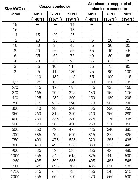
Section 110.14(C) establishes the maximum current that a termination can carry based upon the conductor and the temperature rating of the equipment. This section provides information for when the equipment is not marked and provides requirements for when it is marked. Section 110.14(C) uses Table 310.16 in a different way than how that table is used in other areas of the electrical code. This is one example of a section or table that is used for two different purposes by two different sections of the electrical code. When applying Table 310.16 in relation to the requirements of 110.14(C), the user of the electrical code must ignore the conductor insulation ratings contained in that table and focus only on the temperature values of the table when selecting conductors for the application. These values identify the maximum current permitted through a termination based on the size of the conductor. Table 310.16 in NFPA Link or your copy of the NEC provides these values in a concise manner losing the extra information that Table 310.16 includes that are not pertinent to equipment.
The table of Figure 1 depicts the maximum amount of current permitted through the termination within the equipment when terminating a conductor on that equipment. There are critical factors that must be understood, including the size of the conductor, conductor material, and the temperature rating of the equipment. Larger conductors can carry more current and smaller conductors less current. It’s all about the amount of conductor material present and the amount of current generating heat. The ampere value in the column of this table that aligns with the temperature rating of the equipment is the maximum value of current that the termination can carry for each size of conductor landed on the terminal. We must protect this termination at that ampere value. It is not possible to go to the next larger size OCPD, as is done in the case of a conductor ampacity value that does not align with a standard ampere-rated OCPD. [Ref. 240.4(B).]
To demonstrate the limitations that the equipment places upon the circuit, let’s use the 2 AWG copper conductor with 90°C insulation from example 1. Based on the conditions of use for example 1, the conductor for that application was limited to 60.32A. If this conductor was landed at either end on equipment rated 75°C, the equipment would limit this circuit to 115A, which is the value for the 2 AWG conductor from the 75°C column of Table 310.16. In this case, the ampacity of the conductor based on conditions of use (60.32A) is less than the rating of the equipment within which this conductor is terminated (115A). An overcurrent protective device can be selected such that the next larger OCPD from 60.32A would be adequate to protect the conductor at its ampacity, and the OCPD selected could not be greater than 115A. Based on Table 240.6(A), the next standard OCPD size greater than 60.32A is 70A. This circuit breaker does not exceed 115A and so provides both equipment and conductor protection. The OCPD could never be greater than 115A for this conductor, regardless of the conditions of use.
If the conditions of use for this 2 AWG copper conductor with 90°C insulation had the same conditions of use as those identified in Table 310.16, the circuit would be limited by the termination and not the ampacity of the conductor. The ampacity of this conductor is 130A but because the conductor is terminated in 75°C equipment, the circuit is limited to only 115A. This circuit must be protected at 115A or less (110A OCPD) even though the conductor itself can carry 130A. This same 2 AWG copper conductor with 90°C insulation landed at one end on equipment with a 60°C temperature rating would be restricted to 95A (90A OCPD).
Circuit Selection and Protection
Proper application of a circuit is comprised of understanding the load to be served, selecting the correct conductor for the application, and protecting the conductor and equipment with the proper selection of OCPD. It sounds more complicated than it really is when you understand the fundamentals. Let’s establish the process, align with specific sections in the electrical code, and implement through examples.
I have to say here that we are not exploring the application of Table 310.4(1) as a basic assumption is being made that the proper insulated conductor is being selected for the application. Keep in mind this table is critical to understand the insulation temperature rating of the conductor. This article is omitting that process.
Minimum ampacity based on conditions of use
The minimum conductor size based only on conditions of use is an evaluation that is included for branch circuits [Reference 210.19(A)(2)], feeders [Reference 215.2(A)(2)], and service entrance conductors [Reference 230.42(A)(2)]. This determination is only based on the conditions of use that include adjustments or corrections made to the ampere value located in the column of Table 310.16 that aligns with the temperature rating of the conductor.
Example
Select the correct THHN conductor that can serve a continuous load of 45A in a dry location, an ambient of 145°F and with two current carrying conductors in a raceway. The equipment at both ends of this conductor is rated for 75°C.
For this application, Table 310.15(B)(1)(1) Ambient Temperature Correction Factors Based on 30°C (86°F), requires a multiplier of 0.76 for a 90°C insulated conductor as a THHN conductor has a 90°C insulation as found in Table 310.4(1) Conductor Applications and Insulations Rated 600 Volts.
To address this example, we will divide the load amperes by the adjustment or correction factors and then find the ampacity value in Table 310.16 that is equal to or greater than the calculated value.
Adjusted Load Amps = 45A / 0.76 = 59.21A
Table 310.16 is used to find a conductor size that is equal to or greater than 59.21A. This yields a 6 AWG copper conductor. Multiplying the ampacity of this conductor based on the 90°C column is 75A. Adjusting this ampacity value based on conditions of use yields the following:
Adjusted Ampacity = 75A × 0.76 = 57A
The ampacity of a 6 AWG conductor based on these conditions of use is 57A, which is greater than the 45A of load current and adequate for this application.
Minimum size considering continuous and non-continuous loads
The minimum conductor size based only on continuous and non-continuous load current is an evaluation that is included for branch circuits [Reference 210.19(A)(1)], feeders [Reference 215.2(A)(1)] and service entrance conductors [Reference 230.42(A)(1)]. This evaluation is related to the equipment to which the conductor is terminated. Equipment like an overcurrent protective device (OCPD) is typically evaluated to ensure it can carry continuous current restricting the continuous current to 80% of the rated current of the equipment. The selection of the conductor size to serve this equipment must take continuous current into consideration. To ensure this consideration, a conductor is selected based on an adjusted load current. A multiplier of 1.25 is used as this is the same as dividing the load current by 0.8.
1.25 = 1 / 0.8
The conductor size based on the lowest temperature rated termination must be equal to or greater than the non-continuous load current plus the continuous load current multiplied by 1.25.
Ampere Value ≤ (noncontinuous current)+(1.25)(continuous current)
Example
Select the correct THHN conductor that can serve a continuous load of 45A in a dry location, an ambient of 145°F and with 2 current carrying conductors in a raceway. The equipment at both ends of this conductor is rated for 75°C.
For this example, considering only the continuous and non-continuous current, the adjusted load is calculated as follows:
Ampere Value ≤ (0) + (1.25)(45A) = 56.26A
The conductor size is selected based upon the 75°C column of Table 310.16 because that aligns with the temperature rating of the equipment hence following the rules of 110.14(C). A 6 AWG copper conductor has a value of 65A for 75°C equipment which is greater than the calculated 56.26A. The minimum size conductor based solely on the continuous and non-continuous current and not the conditions of use is a 6 AWG copper conductor.
Minimum size conductor
The minimum conductor size must be the larger of that which was selected based only on conditions of use and that which was selected based on continuous and non-continuous load currents without consideration of conditions of use. The example used thus far yields a 6 AWG copper THHN conductor as being the minimum size conductor for this application.
Minimum size based on conditions of use: 6 AWG Copper THHN conductor
Minimum size based on continuous and non-continuous loads: 6 AWG Copper THHN conductor
The minimum size conductor based on this information is a 6 AWG Copper THHN conductor.
Circuit Protection
The next step in this process is the selection of the OCPD that will provide protection of the conductor and the equipment. Parameters for this circuit must take into consideration the load current, continuous current, conductor ampacity, and finally the maximum current for the equipment based on the temperature rating and size of conductor selected. Once the upper and lower limits for OCPD size are established, if the OCPD does not provide proper protection, changing the conductor size is required.
Some of the parameters to consider include the following:
- The OCPD size must be greater than or equal to the non-continuous load plus 125% of the continuous load. This requirement can be found in 210.20(A) and 215.3. This principle is not found in Article 230 for the service-disconnecting means.
For this 45A load example, the OCPD must be greater than or equal to 45A * 1.25 or 56.25A.
- The OCPD must protect the conductor at its ampacity. This means the maximum size OCPD is equal to or less than the ampacity of the conductor. 240.4(B) permits the OCPD to be the next size larger than the ampacity of the conductor if the OCPD is not greater than or equal to 800A and the ampacity of the conductor doesn’t exactly match a standard ampere rated OCPD. Standard ampere-ratings of OCPDs are found in 240.6(A).
For this example, a 6 AWG conductor is the starting point as the minimum size conductor. A 6 AWG conductor, based on the conditions of use, has an ampacity of 57A. Because of 240.6(A), the largest OCPD that can be used to protect this conductor at its ampacity is a 60A OCPD. The OCPD must not be greater than 60A. It can be less than 60A.
- The OCPD must not exceed the value of current in the column of Table 310.16 that aligns with the lowest temperature rated equipment at either end of the conductor and corresponds with the size of the conductor being considered.
For this example, a 6 AWG copper conductor has a current value of 65A based on the 75°C column of Table 310.16. The OCPD must not be greater than 60A as that is the standard OCPD size of 240.6. A 70A circuit breaker would not be permitted as it exceeds the maximum value of 65A for this size conductor.
For this example, a proper OCPD can be selected for the identified 6 AWG conductor.
- The OCPD must be greater than or equal to 60A – addresses 125% of continuous load.
- The OCPD must be less than or equal to 60A – addresses ampacity of conductor.
- The OCPD must be less than or equal to 60A – addresses termination limitation
The correct selection of OCPD is a 60A device. It meets all of the criterial above.
Let’s review yet another example as follows:
Example
Select the correct THHN conductor that can serve a non-continuous load of 45A in a dry location, an ambient of 86°F and with 2 current carrying conductors in a raceway. The equipment at both ends of this conductor is rated for 75°C.
Let’s walk through the steps previously discussed to address this example.
Step 1: Determine the minimum size conductor based on the conditions of use only.
A THHN conductor capable of carrying 45A would be an 8 AWG conductor based on the 90°C column of Table 310.16.
Step 2: Determine the minimum size conductor based only on continuous and non-continuous current and not on the conditions of use.
The conductor size necessary to handle 45A of non-continuous current through a termination rated for 75°C is an 8 AWG conductor, as it is capable of 50A per the 75°C column of Table 310.16.
Step 3: The larger of the two conductors determined as part of Steps 1 and 2 is selected as the minimum conductor size for this application.
The minimum conductor size is an 8 AWG copper conductor.
Step 4: Select the OCPD to protect the conductor and equipment meeting the three key parameters.
Parameter 1: The OCPD must be greater than or equal to 45A of non-continuous current. A 45A OCPD is a standard ampere-rated OCPD based on Table 240.6(A). The OCPD must be equal to or greater than 45A.
Parameter 2: The OCPD must be less than or equal to the ampacity of the conductor. We can go to the next larger size OCPD as long as it is less than 800A. In this case, the ampacity of the 8 AWG conductor is 55A. The maximum size OCPD is 60A.
Parameter 3: The OCPD must not be greater than the value of current in the 75°C column of Table 310.16 for this 8 AWG copper conductor. In this case, the OCPD cannot exceed a 50A OCPD.
For this 8 AWG conductor, a 50A OCPD would satisfy all there parameters for this application. A 50A OCPD would provide adequate protection for the conductor and for the equipment.
Summary
Mastering ampacity and conductor protection is less about memorizing tables and more about understanding the logic behind the electrical code. By separating conductor ampacity from equipment limitations, applying correction and adjustment factors, and respecting the boundaries of equipment terminations, the process becomes clear and repeatable. The key is to approach each circuit systematically—define the load, establish conditions of use, determine the minimum conductor size, and then select an OCPD that protects both the conductor and the equipment. With practice, what once felt like confusion and complexity transforms into a straightforward application of principles. In the end, proper conductor sizing and breaker protection not only ensures compliance with the electrical code but, more importantly, safeguard the reliability and safety of every installation.
Annex with examples:
Example A1
Select the correct THHN conductor that can serve a continuous load of 104A in a dry location, an ambient of 86°F, and with 2 current-carrying conductors in a raceway. The equipment at both ends of this conductor is rated for 75°C.
- The minimum conductor size based on the larger of the two determinations is a 1 AWG conductor.
a. Conditions of use considerations require a conductor of an ampacity of at least 104A. A 3 AWG Copper THHN conductor would suffice.
b. Continuous current considerations require a conductor to handle 1.25 X 10⁴A or 130A in the 75°C column of Table 310.16. A 1 AWG copper THHN conductor would suffice.
2. Proper OCPD selection to protect the 1 AWG copper conductor with 90°C insulation supply a constant load of 104A must be based on the following evaluations:
a. OCPD cannot be less than a 150A-Rated device. The OCPD must be equal to or greater than the non-continuous load current plus 125% of continuous load current. The OCPD must be equal to or greater than 130A (1.25 X 10⁴A). The next larger standard OCPD size based on 240.6 is 150A.
b. OCPD cannot be greater than a 150A-Rated device. The ampacity of the 1 AWG copper THNN conductor based on the conditions of use is 145A. 4(B) permits protecting a conductor with the next larger size OCPD if the ampacity doesn’t equate to a standard ampere rating of an OCPD. In this case, it is permitted to protect the conductor that has a 145A ampacity with a 150A OCPD.
c. OCPD cannot be greater than a 125A OCPD. Because the lowest temperature rating is 75°C, the maximum current that a termination can handle when a 1 AWG conductor is landed on it is 130A which is that value from the 75°C column of Table 310.16. The OCPD must protect the equipment at that value but not be adjusted to the next larger. The next lower standard ampere rated OCPD based on 240.6 is 125A.
3. The evaluation of step 2 yields the fact that an OCPD cannot be selected and meet all of the conditions. Because the OCPD cannot be greater than a 125A device yet must be at least a 150A device to meet the continuous current requirement tells us that we must increase the size of the conductor from a 1 AWG to a 1/0 AWG conductor.
4. Proper OCPD selection to protect a 1/0 AWG copper conductor with 90°C insulation supplying a constant load of 104A must meet the following evaluations:
a. OCPD cannot be less than a 150A-Rated device. The OCPD must be equal to or greater than the non-continuous load current plus 125% of continuous load current. The OCPD must be equal to or greater than 130A (1.25 X 10⁴A). The next larger standard OCPD size based on 240.6 is 150A.
b. OCPD cannot be greater than a 175A-Rated device. The ampacity of the 1/0 AWG copper THNN conductor based on the conditions of use is 170A. 4(B) permits protecting a conductor with the next larger size OCPD if the ampacity doesn’t equate to a standard ampere rating of an OCPD. In this case, it is permitted to protect the conductor that has a 170A ampacity with a 175A OCPD.
c. OCPD Cannot be greater than a 150A OCPD. Because the lowest temperature rating D is 75°C, the maximum current that a termination can handle when a 1/0 AWG conductor is landed on it is 150A which is that value from the 75°C column of Table 310.16. The OCPD must protect the equipment at that value but not be adjusted to the next larger.
Based on the evaluation for the 1/0 AWG copper conductor, a 150A OCPD will adequately protect a 1/0 conductor and the equipment for this application.
Example A2
Select the correct THHN conductor that can serve a continuous load of 104A in a dry location, an ambient of 125°F and with 4 current carrying conductors in a raceway. The equipment at both ends of this conductor is rated for 75°C.
- The minimum conductor size based on the larger of the two determinations is a 2/0 AWG copper conductor.
a. Conditions of use considerations requires a conductor of an ampacity of at least 104A adjusted by 0.8 for 4 conductors in a raceway and 0.76 for the 125°F ambient. This equates to a value of 171.05 [(104A) / (0.8 x 0.76)]. A 2/0 AWG Copper THHN conductor would suffice for this application which has a 195A ampacity based on the 90°C column of Table 310.16.
b. Continuous current considerations requires a conductor to be selected based on 1.25 X 10⁴A or 130A in the 75°C column of Table 310.16. A 1 AWG copper THHN conductor would suffice.
- Proper OCPD selection to protect the 2/0 AWG copper conductor with 90°C insulation supplying a constant load of 104A must be based on the following evaluations:
a. OCPD cannot be less than a 150A-Rated device. The OCPD must be equal to or greater than the non-continuous load current plus 125% of continuous load current. The OCPD must be equal to or greater than 130A (1.25 X 10⁴A). Based on 240.6, the next standard ampere rated device is 150A.
b. OCPD cannot be greater than a 125A-Rated device. The ampacity of the 2/0 AWG copper THNN conductor based on the conditions of use is 195A X 0.8 X 0.76 = 118.6A. 240.4(B) permits protecting a conductor with the next larger size OCPD if the ampacity doesn’t equate to a standard ampere rating of an OCPD. In this case, it is permitted to protect the conductor that has a 118.6A ampacity with a 125A OCPD.
c. OCPD cannot be greater than a 175A OCPD. Because the lowest temperature rating is 75°C, the maximum current that a termination can handle when a 2/0 AWG conductor is landed on it is 175A, which is that value from the 75°C column of Table 310.16. The OCPD must protect the equipment at that value but not be adjusted to the next larger.
- The evaluation of step 2 yields the fact that an OCPD cannot be selected and meet all conditions. Because the OCPD cannot be greater than a 125A device yet cannot be less than a 150A device we must increase the size of the conductor from a 2/0 AWG to a 3/0 AWG conductor.
- Proper OCPD selection to protect a 3/0 AWG copper conductor with 90°C insulation supplying a constant load of 104A must meet the following evaluations:
a. OCPD cannot be less than a 150A-Rated device. The OCPD must be equal to or greater than the non-continuous load current plus 125% of continuous load current. The OCPD must be equal to or greater than 130A (1.25 X 10⁴A). Based on 240.6, the next standard ampere-rated device is 150A.
b. OCPD cannot be greater than a 150A-Rated device. The ampacity of the 3/0 AWG copper THHN conductor based on the conditions of use is 225A X 0.8 X 0.76 = 136.8A. 4(B) permits protecting a conductor with the next larger size OCPD if the ampacity doesn’t equate to a standard ampere rating of an OCPD. In this case, it is permitted to protect the conductor that has a 136.8A ampacity with a 150A OCPD.
c. OCPD cannot be greater than a 200A OCPD. Because the lowest temperature rating is 75°C, the maximum current that a termination can handle when a 3/0 AWG conductor is landed on it is 200A, which is that value from the 75°C column of Table 310.16. The OCPD must protect the equipment at that value but not be adjusted to the next larger.
Based on the evaluation for the 3/0 AWG copper conductor, a 150A OCPD will adequately protect a 3/0 conductor and equipment for this application.