Prior to the 2002 version of the National Electrical Code® (NEC®), incident energy and arc flash requirements were found in NFPA 70E, “Standard for Electrical Safety in the Workplace.” That is until the NEC introduced Section 110.16, Arc-Flash Hazard Warning, as part of NEC 2002. The submitters’ substantiation for this, then new, requirement summed up why it is important that the NEC include provisions to address the challenges and hazards of arc-flash. “Significant numbers of electricians are being seriously burned and often killed from an accidental electrical flash while working equipment ‘hot.’ Most of these serious accidents can be eliminated or significantly reduced if the electricians wear the proper type of protective clothing.” The intent of 110.16 in the NEC is to help ensure electrical workers wear proper PPE where justified energized work must be performed.
Today we are going to take a deeper look at 110.16 as it was recently modified during the NEC 2017 revision cycle. It has been separated into two first level sub-divisions with the existing language that has been in the NEC since NEC 2002 retained as first level subdivision (A) General, and a new labeling requirement is added in, (B) Service Equipment.
In this article, we will review what installations are impacted, what the options are for compliance, and reference other requirements of the NEC that we need to be aware of. In the next IAEI magazine, we will provide a real-life example for the practical application of this requirement.
Requirement Purview
We begin with an understanding of where this requirement has purview. We are in Chapter 1. Article 110 and its contents are general requirements for all electrical installations unless modified by those requirements found in Chapters 5, 6, or 7. Section 110.16(A) is a general requirement for electrical equipment located in other than dwelling units that will likely require examination, adjustment, servicing, or maintenance while energized. The electrical equipment includes but is not limited to:
- Switchboards
- Switchgear
- Panelboards
- Industrial control panels
- Meter socket enclosures
- Motor control centers
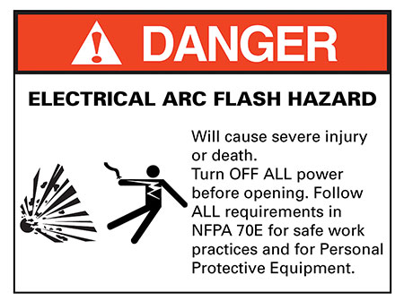
The requirement of 110.16(A) mandates a general arc flash hazard warning label, nothing more. (Reference Figure 1).
NEC 2017 introduced the new first level subdivision 110.16(B) Service Equipment. This new addition applies only to service equipment rated 1200 amps or more. Note that this is the rating of the equipment, not the rating of the OCPD protecting the service equipment.
Options for Compliance
There are two ways to satisfy the requirements mandated in 110.16(B). The first is a straight application of the requirement in positive text. The second is through the application of the exception to 110.16(B). They are illustrated as follows:
Applying the positive text of 110.16(B)
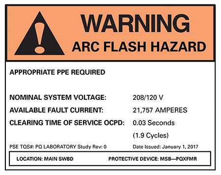
Provide a label that includes the following:
- Nominal system voltage
- Available fault current at the service overcurrent protective devices
- The clearing time of service overcurrent protective devices based on the available fault current at the service equipment
- The date the label was applied
Outside of the positive language found in 110.16(B) for labeling, there is an exception noting that “Service equipment labeling shall not be required if an arc flash label is applied in accordance with acceptable industry practice.” Let’s review this exception in detail as it is important to understand how it applies and will be used in practice.
Applying 110.16(B) Exception
The exception to 110.16(B) permits an alternate method where “an arc flash label is applied in accordance with acceptable industry practice.” This exempts all of the positive text of 110.16(B). It is important to understand “all of the requirements” for the arc flash label in an acceptable industry practice. The new informational note explains that acceptable industry practices are described in NFPA 70E. This means that where the exception is applied, all of the requirements that pertain to “application of an arc flash label” in NFPA 70E are enforceable.
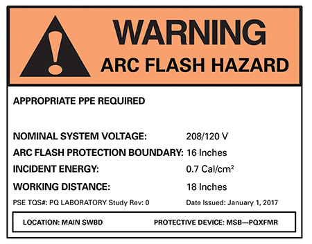
The labeling methods in 70E are based on one of two arc flash risk assessment methods which include calculation of incident energy or the application of the arc flash PPE category method, commonly referred to as the table method. The requirement is found in NFPA 70E Section 130.5, Arc Flash Risk Assessment, and requires that a label be placed on the equipment that includes the following:
- Nominal system voltage
- Arc flash boundary
- At least one of the following
- Incident energy and corresponding working distance or the Arc Flash PPE Category, not both
- Minimal arc rating of clothing
- Site-specific level of PPE(See Figure 3).
Label Discussion
The contents of the label will depend upon which method is used to satisfy this requirement found in 110.16(B). The label as required in the parent text of 110.16(B) must adhere to 110.21(B) and include the following information:
- Nominal system voltage
- Available fault current at the service overcurrent protective devices
- The clearing time of service overcurrent protective devices based on the available fault current at the service equipment
- The date the label was applied
Let’s address each of these bullet items but first remember that the requirements found in 110.21(B) mandate that where caution, warning, or danger signs or labels are required, the labels have to adequately warn of the hazard using effective words and/or colors and/or symbols. The labels must be permanently affixed to the equipment or wiring method and not be handwritten. And finally, the labels have to be of sufficient durability to withstand the environment. These are important characteristics that we cannot forget whether inspecting or creating such labels.
Nominal voltage
The first item included in the list of things required for the label is nominal voltage. This is the nominal voltage at the location of the service equipment and not the ratings of the equipment. For example, you may have 600 V equipment but the nominal voltage at that location is 480, 208 or 240-volts. Section 110.4, Voltages, requires that throughout the NEC, voltage shall be considered to be that at which the circuit operates. It also requires that the voltage rating of electrical equipment shall not be less than the nominal voltage of a circuit to which it is connected.
Available Fault Current
Application of the positive text in 110.16(B) requires obtaining the maximum available short-circuit current. This information has been required to satisfy Section 110.24 since NEC 2011. This is not arcing current. 110.16(B)(2) clearly requires the marking of “available fault current” at the service OCPDs. If the technical committee (CMP-1) wanted marking of arcing current, they would have put that in the requirement.
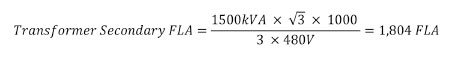
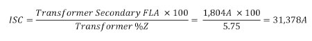
The available fault current can be obtained from the utility and is typically the maximum available fault current that is possible at the secondary terminals of the utility transformer, assuming an infinite bus on the primary of the utility transformer. The calculation for this value is made as follows:
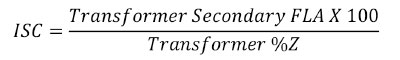
If we use an example 1500 kVA transformer, 4160/480 and 5.75% impedance, we calculate the maximum available fault current that the secondary of the transformer before any conductor run to the equipment.
The available fault current at the service entrance equipment is calculated using standard tools that consider the length of conductor run from the transformer. Free downloads such as Eaton’s Bussmann division Fault Current Calculator can be used to establish these values.
Application of 110.16(B) Exception permits two methods of arc flash risk assessment, as found in NFPA 70E, to be applied to an arc flash label. The first is the incident energy analysis method which uses a “calculated value of short circuit current available” from the utility and not the maximum available fault current that the utility typically provides. Depending upon the utility and how they derive these values, the “calculated value of short circuit current available” and the utility maximum available fault current may be the same value. This value is NOT an infinite bus calculation. Since this is the Exception, this fault current value is NOT printed on the arc flash label; it is simply used in the calculation to determine the level of incident energy available. The table method uses an “estimated maximum available short circuit current.” Again, this fault current value is NOT printed on the arc flash label; it is simply a parameter used in the table method to determine an Arc Flash PPE category.
Clearing Time
Each method of compliance with 110.16(B) requires a determination of clearing time of the upstream overcurrent protective device and is used in some manner to create the label. NEC 110.16(B) is only requiring that the characteristics of the service OCPD be considered. NEC 110.16(B) doesn’t provide clear direction for those applications where the service entrance equipment rated at 1200 amps or higher does not include a main OCPD but rather 2 – 6 OCPDs as permitted by Section 230.90(A) Exception No. 3. In this case, the installation can take the most conservative approach which would be to make an individual determination for each OCPD and apply a label with the most conservative requirements.
Obtaining clearing times for OCPD devices can be achieved from various sources including
- Software applications that are used for selective coordination studies
- Manufacturer websites where TCC curves can be accessed (www.eaton.com/tcc).
- Where the table method is applied, application of typical clearing times. NFPA 70E 2018 includes an informational note with typical device clearing times to aid in the application of the table method.
Date
The last part of the positive text of 110.16(B) is the Date. The only time a date is required to be placed on this label is when the positive text of 110.16(B) is applied to create a label. When the exception to 110.16(B) is leveraged, and NFPA 70E is used to create the label, a date is not required.
Related Code Requirements
The new requirement in 110.16(B) is safety driven and is perhaps the first step towards labeling of all electrical distribution equipment with a prescriptive arc flash label. There are other requirements for this same equipment that include:
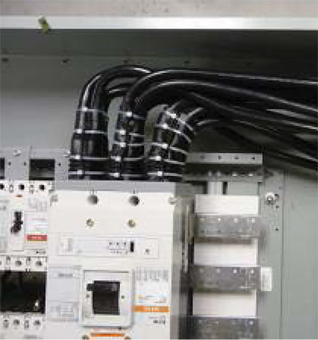
- 3(A)(2), Service Panelboards, Switchboards, and Switchgear
- 87, Incident Energy Reduction
- 67, Incident Energy Reduction
- 95, Ground-Fault Protection of Equipment
408.3(A)(2), Service Panelboards, Switchboards, and Switchgear
NEC 2017 has expanded a provision that is intended to provide more protection for those who work on or maintain service entrance panelboards where it is likely that the line terminals from the utility will be energized while work is performed. Article 408 focuses on Switchboards, Switchgear, and Panelboards. A review of some of the history associated with this section is quite telling.
NEC 1978 Section 384.3, Support and Arrangement of Busbars and Conductors, introduced the requirement for switchboards and Panelboards that “Barriers shall be placed in all service switchboards that will isolate the service busbars and terminals from the remainder of the switchboard.” The substantiation submitted with this proposal noted “Since it is usually impossible to kill the service feeding a service switchboard, it is universal practice to work on these switchboards with the service bus electrically alive. There can be no question of the serious hazard involved. Switchboard manufacturers have been supplying switchboards with these required barriers to several parts of the country that presently have this requirement. There is no real reason why all switchboards should not be made this way.”
NEC 1999 modified 384-3(A)(2) Service Switchboards and added a requirement for barriers on all service switchboards such that no uninsulated, ungrounded service busbar or service terminal will be exposed to inadvertent contact by persons or maintenance equipment while servicing load terminations. This change addressed issues around previous text noting that barriers are usually removed when servicing equipment and so energized components are exposed. The panel wanted to assure that personnel could not come in contact with these service entrance busbars as well as ensure a dropped tool would not come into contact with an energized service bus or service terminal doing routine maintenance.
NEC 2002 moved this article from Chapter 3, Wiring Methods and Materials (Article 384, Switchboards and Panelboards), to Chapter 4, Equipment for General Use (Article 408, Switchboards and Panelboards).
NEC 2014 modified the title of Article 408 from “Switchboards and Panelboards” to “Switchboards, Switchgear and Panelboards.” The term switchgear was added to various sections within this Article.
NEC 2017 expanded the requirements of 408.3(A)(2) by adding the word “Panelboards” to the list of equipment found in this Section. A new exception recognizes the challenges for applications where panelboards are used as well as when 2 – 6 service disconnects are employed as per Exceptions 1, 2, and 3 of Section 408.36. Those installations employing the “6 – Disconnect Rule” are now not afforded the same level of protection as those that employ a main disconnect. This new requirement applies to all panelboards, including residential panelboards commonly referred to in the industry as load centers.
240.87, Incident Energy Reduction
This section seeks to provide energy reduction methods for those applications more likely to have higher incident energy values due to longer clearing times for reduced values of arcing currents. First introduced as part of NEC 2011, this requirement focused on circuit breakers without an instantaneous trip. Modified as part of NEC 2014, this section now addresses any circuit breaker where the highest continuous current trip setting for which the actual overcurrent device installed in the circuit breaker is rated or can be adjusted to 1200 A or higher.
Section 240.87 requires documentation as well as one of the following technologies installed for these installations:
- Zone-selective interlocking
- Differential relaying
- Energy-reducing maintenance switching with local status indicator
- Energy-reducing active arc flash mitigation system
- An instantaneous trip setting that is less than the available arcing current
- An instantaneous override that is less than the available arcing current
- An approved equivalent means
There are no exceptions to this requirement. New for NEC 2017 is recognition of an instantaneous trip setting or instantaneous override where the arcing currents are in the instantaneous region as a method to reduce incident energy.
240.67, Incident Energy Reduction
This section, introduced as part of NEC 2017, seeks to provide energy reduction methods for those applications more likely to have higher incident energy values due to longer clearing times for reduced values of arcing currents. This requirement is the first of its kind for fuse applications in the NEC as Section 240.87 only applied to circuit breakers. The effective date for enforcement of this requirement is January 1, 2020.
There are no exceptions to this requirement and documentation is required. For fuses, where the arcing current clearing time is greater than 0.07 seconds, one of the following technologies must be employed:
- Differential relaying
- Energy-reducing maintenance switching with local status indicator
- Energy-reducing active arc flash mitigation system
- An approved equivalent means
230.95, Ground-Fault Protection of Equipment
This section of the NEC has been around a while as it was introduced as part of NEC 1971 to prevent burn downs. Section 230.95 requires that ground-fault protection of equipment be provided for solidly grounded wye electric services of more than 150 volts to ground but not exceeding 1000 volts phase-to-phase for each service disconnect rated 1000 amperes or more. This is a requirement for installations that have the grounded conductor for solidly grounded wye systems connected directly to ground through a grounding electrode system, as specified in 250.50, without inserting any resistor or impedance device. The rating of the service disconnect is considered to be the rating of the largest fuse that can be installed or the highest continuous current trip setting for which the actual overcurrent device installed in a circuit breaker is rated or can be adjusted. The ground-fault protection system shall operate to cause the service disconnect to open all ungrounded conductors of the faulted circuit. The maximum setting of the ground-fault protection shall be 1200 amperes, and the maximum time delay shall be one second for ground-fault currents equal to or greater than 3000 amperes.