In this article we will conclude our discussion of Chapter 3 of the 2011 National Electrical Code. Starting with Article 366, we will cover various portions in the code that I believe are relevant to a combination inspector, concluding with Article 394. As in the past, we are not going to cover every article in this portion of the code, partly due to time and space considerations, but mainly due to our focus on the information and items that are most relevant to a combination inspector’s application of the electrical code. Since this article is only an overview, you will need to follow along in the code to fill in the blanks of the material discussed.
Gutters and Wireways
Since Article 366 Auxiliary Gutters, Article 376 Metal Wireways, and 378 Nonmetallic Wireways are very similar, we will discuss them as a group. They are listed to UL Standard 870. All of these items serve as an enclosure for conductors, they look the same and perform essentially the same function; the difference is how they are marked and identified. If the label on one of these products states Gutter, then it must be used in accordance with Article 366. The unique feature of a gutter is found in 366.2, where we find the definition of a gutter. It states that it is to be used as a supplemental wiring space for other equipment. So, from this language, we know that if an enclosure is listed as a gutter, then it must be installed in combination with meter centers, distribution centers, switchboards, etc.; it can’t be used as a stand-alone wireway or raceway.
Some of the items you need to watch for on Gutters are found in 366.12 Uses Not Permitted, which states that no switches, overcurrent devices, appliances or similar equipment shall be enclosed, and the gutter shall not extend more than 30 feet from the equipment to which it is serving as an auxiliary. Another item unique to gutters is the securing and supporting found in 366.30. Gutters are to be supported and secured throughout the entire length at intervals not to exceed 5 feet. Notice it doesn’t just say supported, but also secured, so this is often an additional requirement. Supporting means it can rest on a support without being attached; securing means it has to be attached.
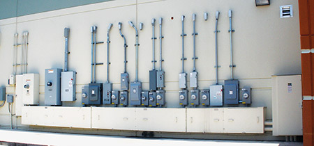
Photo 1. This is a Bus Gutter made in Texas that is fed by the 1200 amp disconnect at the very right of the photo. As you can see, it has allowed several taps to be made which feed different tenants.
Now we will cover the wireways, and I will note which of these items are also common to gutters. Wireways are basically raceway systems that are constructed in a boxy rectangular design. Wireways are typically a modular design with fittings permitting change of directions, “T” fittings and “X” fittings, and these generally require a coupler. Of course, we have to close any open ends of a wireway. Remember, wireways are basically a form of a raceway and have no limits to their length, and the securing and supporting methods are dependent on the orientation (vertical or horizontal). Horizontal installations shall be supported at each end and at intervals not to exceed 5 feet. If we have a continuous length longer than 5 feet, we have to support at each end or joint, which makes sense as the joints become our weak points. Sometimes these may have a listing permitting a different distance requirement, but if this is the case, have the contractor furnish you the information. In a vertical installation, we have to securely support at intervals not to exceed 15 feet; however, you can’t have more than one joint between these secure supports.
Now let’s cover some of the common items for all of these, starting with splices and taps. We are permitted to make splices and taps within wireways and gutters, but we can’t fill the wire way more than 75% at the point of a splice or tap. Years ago, we used to find split bolts used within enclosures, and often they took up so much space that we would find pieces of wood stuck in the lips of the wireway to hold the wire and split bolts inside so that you could get the cover on. In my mind, the preferred method to make taps or splices is the use of power distribution blocks. This is a much cleaner installation method; just remember that they have to be listed and have an insulating cover to make them finger safe, and they must be accessible.
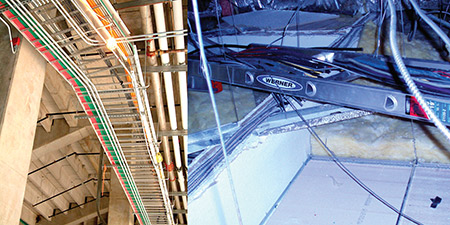
Photo 2. As inspectors and service electrical contractors, we often stumble onto some unique installations. On the left, we have a ladder cable tray properly installed, on the right you will find an actual ladder used as a cable tray – you never know what you will find! (The ladder installation was found by Roberts Electric in Las Vegas.)
Another common inspection item is the number of conductors, which is not allowed to exceed a 20% fill of any cross-sectional area. Also, if you have more than 30 current-carrying conductors at any cross section of the wireway, then the adjustment factors of 310.15(B)(3)(a) must be applied. These two items are often overlooked by inspectors; so just remember that wireways and gutters are not free territory. We have to address the cooling and heat dissipation problems that occur whenever you have a mass of current-carrying conductors and spacing is not provided, as is the case where they lay bunched up in the bottom of an enclosure.
Also, if conductors are being deflected or changing directions, for instance going out a connector, we will have to meet the requirements outlined in 312.6(A). If we are using these items as pull boxes, then we have to follow the requirements of Article 314 for sizing, depending on whether it is a straight pull or an angle pull. Remember, I just hit the highlights on Gutters and Wireways, so please refer to the code for more details. Then when you come across a wireway or gutter, you will know the unique requirements for each and the common requirements that apply. Also, please look closely at the label to see exactly what you have and then you will know how to enforce the code. The label will also help you determine if the gutter or wireway is listed for the environment (for example, indoors or outdoors).
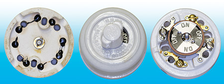
Photo 3. This is a knob and tube switch. Showing the back of the unit on the left, center is the entire switch and on the right is the switch with the cover removed showing the termination points.
Busways
In Article 368, we find the requirements for Busways. These are metal enclosures that contain factory-mounted conductors, such as copper or aluminum bars, rods, or tubes. Some of the items you need to pay special attention to here are the support requirements in 368.30, which has a maximum spacing of 5 feet. Please make sure you check this, as I have found times where they only support it at each floor. Sometimes you may find that a manufacturer will have different requirements, and this is permitted if the busway is marked that way. The other common inspection item addresses taps on the busway for a disconnect switch or overcurrent device, in which case the code kicks in for the maximum height of a switch and proper working clearances. Another inspection item to be aware of on busways concerns cord drops from the busway to power equipment. If you find these, then make sure you review the conditions required in 368.56(B). We can’t simply make a cheap cord from a non-metallic sheathed cable and connector, although it has been tried many times!
Cablebus
I will discuss Article 370 Cablebus only briefly. I’ve only seen it installed a couple of times, but I want you to be aware of it. It is an assembly of insulated conductors completely enclosed in a metal housing. It is generally assembled on site. The big advantage to using cablebus is that the ampacity of the conductors are based on a rating in free air as outlined in 370.4(B). This provides a huge advantage, so you may start to see this in the future due to the high prices of the materials used to make conductors. If you stumble on to a cablebus installation, get into Article 370 fast.
Multioutlet Assembly
Now we will jump up to Article 380 Multioutlet Assembly. If you do a computer search for “multioutlet assembly” the first thing that will come up is Wiremold. This is the trade name often used for this wiring method, but it is also a manufacturer’s name, which just happens to be the largest maker of these surface-mounted raceway/outlet assemblies. These assemblies are a surface-mounted wiring method generally used to provide power to locations that have a lack of sufficient outlets, such as along work benches and school lab counters. They are also excellent in retail establishments where there are various display cabinets that need power to sales equipment. This is a very short article, but we have specific conditions that must be followed, the most important being that they have to be installed only in dry locations and shouldn’t be concealed.
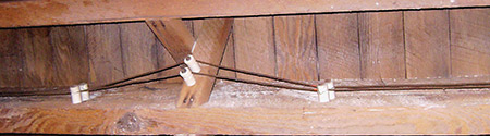
Photo 4. Here is an example of knob and tube wiring still installed in a facility.
There are two other articles that have a similar product; these include Article 386 Surface Metal Raceways and Article 388 Surface Nonmetallic Raceways. These are often used along concrete walls where we don’t have the ability to provide concealed wiring methods once the construction has been completed. Remember to take a close look at these installations, as I have seen instances where they didn’t effectively clean up field cuts of the pieces to deburr them. This is important to make sure we don’t have any sharp or rough edges that will cause damage to the conductors inside. Also, make sure that the proper factory-made fittings are used when going around corners, or making transitions from normal conduit, or from one size to another. Some of these larger assemblies also have individual chambers for different wiring systems, which could include telephone, computer and other systems that are not allowed to be run with power conductors. The manufacturers actually publish a very good pocket catalog that I used to carry in my truck, which helped when I was an electrician and an inspector.
Strut-Type Channel Raceway
Another raceway I want to make you aware of is covered in Article 384 Strut-Type Channel Raceway. This is a raceway system that is made from strut, which we generally use to mount and support electrical equipment. Strut is the universal method used for wiring installations due to the ease of use and the wide arrangement of fittings, sizes and materials that make it compatible with any location. This article covers an entire set of fittings and accessories that make the common u-shaped strut into a wireway through the use of snap-in covers and other pieces. I personally thought we’d see a lot more of this used for photovoltaic installations to provide protection of the conductors. However, I haven’t seen it applied there, even though strut is typically used to mount the PV equipment. Instead, we frequently see these conductors running exposed (often not in the most attractive method) and looped from tie-wrap to tie-wrap. The conductors are listed to be run exposed so it is code- compliant; however, it just doesn’t provide a lot of protection in my opinion. Sometimes you will see strut raceway systems used to run the conductors and provide support for lighting fixtures. So just be aware that this is an approved raceway system and it has its own article where it covers the fill, conductor ampacity adjustments, splices, mounting and grounding.
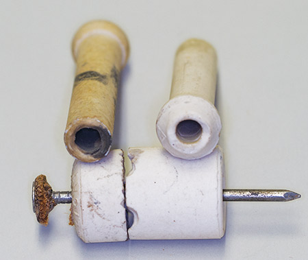
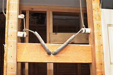
Photo 5. Here is a close up photo of typical knob and tube insulators. The knobs provide conductor support when run along framing members and the tubes provide protection when running through framing members.
Underfloor Raceways
Article 390 covers Underfloor Raceways. These are used more than you probably realize; most of the larger grocery chains all have underfloor raceways that contain all the required wiring to the checkout stands. These come in various configurations, totally concealed under the concrete floors or exposed where the top covers of the raceway are exposed, with removal covers. The common names associated with these are Walker Duct for the concealed (again this is a manufacturer’s name, but the industry uses it as a slang term for this type of system) and the exposed system is called trench duct, which signifies that the duct is like a trench, with the top covers being exposed. The trench duct is often used in medical installations for the required wiring needed for various pieces of equipment, such as X-ray, CT-scan, and MRI equipment. When I worked as an electrician, we were often called upon to add to the underfloor systems in grocery stores for additional check-out locations. It takes a little care to locate the proper channel you want to drill down to for the installation of the insert for the new location. Often, you are drilling through several inches of concrete, then into the metal raceway, while not damaging any conductors that may be in the duct. I would personally oversee my employees during this process to make sure we didn’t knock out the power to the existing cash registers in the store.
Cable Trays
Next in the code is Article 392 Cable Trays. This is an article that went through an entire reorganization in the 2011 code cycle, as you can see in your books by the vertical lines alongside the text. We won’t cover this article in depth, but please read this article (which is several pages long) if you have a cable tray installation in your area. A few warnings with tray: be careful to make sure the system is properly grounded, look for any sharp edges that may cause damage to the conductors, make sure it is supported properly, and make sure that the proper conductors are installed. Also make sure the correct fittings are used for any directional changes; I have seen some real butcher jobs when attempts have been made to do cable tray installations. If you have any doubt, check with the manufacturer’s published information to make sure you are doing a good inspection of the system. At times, these installations get abused and misapplied, so make sure it’s right when you do your inspection. We can’t control what happens after we are gone, but at least we can make sure it is done properly at the beginning.
Concealed Knob-and-Tube Wiring
The last article I will cover in this issue is Article 394 Concealed Knob-and-Tube Wiring. While it is rare to find this wiring method in use today, there are still systems in operation. It has always been one of my favorite, due to its rarity and simplicity. In many cases those who live in homes with this type of system don’t know it, since as far as they are concerned the power is there when they plug in a cord or turn on a light. This system is perfectly good if it has been maintained properly and hasn’t been damaged in any way. As mentioned in 394.10 Uses permitted, it is still allowed to use this type of installation in existing locations having this method and by special permission. What it consists of is a system of individual conductors run between supports (known as knobs). Where these conductors pass through framing members, they must pass through a tube, which is generally made of a porcelain or glass for isolation and protection. I will include several photos of these systems so you can see what they look like.
Once again, we are at the end of an article. I remind you to use your codebook to follow along as you read these articles and fill in the details I have passed over. This will make you a better code person whether you are an inspector or contractor. Anytime you get more familiar with the code, the better we all are.