This is a question many inspection departments ask as budgets for governmental agencies are scrutinized and cut back. It is the field inspector that has the visibility to the customer, so this is where the priority also seems to be set. Just recently I was at a meeting with other inspection jurisdictions in the area and one is having some personnel changes and where do they cut at this time? Plan review. The state rules in my area require electrical plan review only for health care, education, and prisons. It leaves the entire inspection process to the field inspector for large commercial and industrial projects.
In my last eight years of doing electrical plan review, it has been amazing the number of code violations I find daily. Many of these violations are items I would have overlooked when I was doing field inspections. Electrical systems seem to be getting more and more complex with the use of computerized control systems and complex alternate power systems. I really do not know how a field inspector running from project to project could ever do a really complete inspection without the aid of the plan review tool.
Who benefits from an electrical plan review?
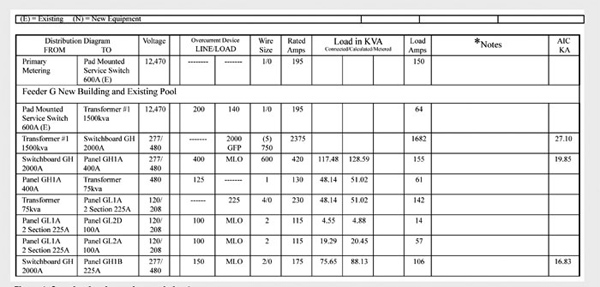
Figure 1
Plan review benefits many: the field inspectors, the designer/engineer, and the end user customer. A plan review should first of all create a tool for the field inspector, in order for a thorough inspection to be made. It should also reduce the time spent in the field inspection process because many issues have been looked at ahead of time. The designer/engineer may receive some of the biggest payoffs. Finding missing or wrong equipment on paper is much easier than finding problems in the field, after it is installed. Imagine a new 1200-amp switchboard with 6 mains being installed when it is required to have a main breaker or no second level of ground-fault protection in a switchboard in a health care facility. These can be very major repairs after installed but if caught during plan review, it just requires the right equipment ordered in the first place. The end user will have a finished project that is less likely to have any code violations when this extra process is added to the inspections.
Does the NEC address electrical plan review?
In the 2002 NEC, Article 80 was added and in the 2005 this has moved to annex G. This section lays out how to set up an electrical inspection program, and plan review is spelled out as a part that can be used. Also, Section 215.5 Feeder Diagrams is basically the outline for needed documents used in plan review.
Who should do the plan review?
Both of the inspection agencies I have worked for and most of the others in the area have an electrical plan review staff, which has this specific task. I really see pluses and negatives for this system. The plus is, once the staff is trained and has the system down, the process becomes much more thorough and much quicker. The negative is, having done plan review I believe I am now a much better field inspector and really have a better understanding of items that need to be looked at much closer. I would have to say that if an individual has the skills and time to do both, starting with the plan review and then doing the field inspections on the same job could be the best option.
Should the reviewer have engineering experience?
Having worked in an engineering office and then working as a wireman and inspector, I believe that someone with hands-on field experience would probably have better Code perspective. Most of the engineers are very good at knowing how to make the system work but sometimes overlook the code violations that a full-time student of the Code will catch.
The process of a plan review will vary from person to person just as the inspection of a single-family residence varies. The first thing I do when receiving a new plan is to log it into a database, assigning it a number and a place in line for review. A quick screening or run-though is done to make sure all the needed information is included with the submittal. If not, two options are available: one, to just reject the plans and send them back; the other is to ask via fax or email for the information needed. You notice I recommend fax or email. I really try to use these written medias rather than just phone calls, because this way both your correspondence and the engineer/designer’s correspondence are in writing and you can file it for future reference. A good filing system with these correspondences and other information is very important when issues arise in the field or at a later date.
When a plan comes up for the review process then the putting of the pieces together really begins. The plans on many projects are like a puzzle that needs to be aligned in order to understand the system. Many questions must be asked and answers searched out. I will spend some time with sticky notes or a note pad just thumbing through the sheets and making notes just to understand the scope, find schedules, and any other information that is needed in the review process. I may make tabs with post-its for the sheets with information that will be referenced through the process. I also normally photocopy the panel schedules and lighting schedule input volt-amps so these can be referenced while working on the plan sheets.
What is the facility?
The next question asked is, Is it a commercial building, residential, industrial, healthcare, and does it have a place of assembly? Do the units of an assisted living facility meet the requirements of a dwelling unit? These and many other questions must be answered in order to know what direction and requirements apply. In recent code cycles, the construction type has become important in order to know if NM cables can be used. Many of these questions are important for the review but, also, as equally important to note for the field inspector.
Where is it located?
Another one of the big questions that must be answered is where is the location of the service point as defined in NEC 100? This is where the review must start and NEC requirements followed. In the area I have been working, more and more we are seeing the service point out at some primary voltage metering point and the customer owning the primary distribution system on the site. Now this primary system must meet NEC requirements rather than utility standards. This can create many problems with service disconnects, transformer secondary conductor protection (240.21), and grounding.
What is the main review process?
After I have the scope somewhat hammered out, then comes the main review process. I spend time verifying loads from the plan sheets to the panel schedules. This will vary from project to project and will normally depend on what is found as to the detail. I do a few random checks of outlet and lighting counts on each plan. If things check out, then I may move on. If I start finding inaccuracies, then more time must be spent. The personal system I use is to use different colored highlight pens for the different load types on the panel schedule. This really speeds up the load calculation process. I may also at this time look at the designer’s load calculations for the service and feeders. If these have extra capacity, then branch circuits load verification may not be so critical. On the other hand, I have had projects where the NEC calculated load is within amps of the service capacity. Some designers push these to the limit because they figure they can just use meter demand calculations after the project is up and running for future expansion. On projects like these I may have to verify each and every circuit in order to make sure no errors have been made.
The random check of branch-circuit loads seems to work fine for receptacles and lighting; but when it comes to HVAC, kitchen equipment, and motor loads, I normally check all of these to the panel schedule loads. Just one or two missed or incorrect loads of larger equipment can really cause problems with distribution system equipment sizing. I also always verify all loads installed on panels fed from emergency power sources. These are so critical and misplaced loads seem to be common on these panel schedules.
During the branch circuit verification stage, other items come to light. Hazardous (classified) locations may be spotted by the types of equipment being serviced. If so, I will then ask for the documentation that is required by NEC 500.4(A). This documentation will then become part of the approved set of plans for the field inspector’s use.
Other issues that can be looked at—such as outlet spacing, required number of outlets for health care facilities, and other circuit types of items—can all be part of this circuit verification process.
If it is health care facility, many other questions must be answered. Does it have critical care areas, where are the patient care areas, are there wet locations, is it a hospital, nursing home, or other health care facility? These types of facilities really require close scrutiny, as many extra requirements are needed for safety of the occupants during a power outage and the possibility of electrocution during procedures. Items that must be checked include: number of outlets, grounding, ground-fault protection, emergency and standby systems.
All facilities with emergency power systems must also be looked over much more carefully. What loads are on which branch of the backup system, and how many transfer switches have been installed? Are the NEC 700 emergency systems run in their own raceway system and not intermixed with other wiring systems? Are battery emergency lights on the normal lighting circuits for the area served? Does the system require load shedding? These are all common areas of corrections found during the plan review process.
How are load calculations handled?
Once I have panel schedules that I feel are accurate, I then move on to the load calculation portion of the review. A plan reviewer must know Article 220 inside and out. I normally just do my own calculations on how I see the system, using the color code from the load verification process to plug the loads into the correct categories. I use a spreadsheet program for this process but these can also be done by hand. Once I have completed my calculations then I will look at the designer’s loads. Many times we may have items a bit different, but a lot of the time the calculated load is very close. If I find major discrepancies, then the search begins for why. One of the major errors I find is designers not carrying the categories through downstream in the distribution system and using only the connected loads or even having entire panels dropped in calculations. Another common error is applying code diversity multiple times on the same loads at different parts of the distribution system.
Much care must be taken when the designer uses metered demand calculations as allowed by NEC 220.87. I find many designers that attempt to subtract connected load removed during remodel from a meter demand calculation. The only way this could even be considered as valid is if the loads could be verified at full load during the metered peak (this normally cannot be verified). Other things that need to be considered with a 30-day demand reading are heating and cooling loads and occupancy of the facility at time of peak demand. It seems each year I do school portable classroom reviews and designers submit metered demand records during summer months with no students in class.
Why is the one-line diagram important?
Once I have load calculations competed then I move on to the one-line diagram. This is probably the one most important document for both the plan reviewer and the field inspector. Because of the importance, I build a worksheet that goes through the entire distribution service and feeder system. Each service or feeder has a separate line in my worksheet and, when completed, gives the inspector an easy-to-carry 8 ½ x 11 package to use in the field. This is also my tool to verify each feeder for loading, sizing of overcurrent protection, conductor sizing and equipment sizes. Each feeder has the starting equipment or panel, ending equipment or panel, voltage, phase, starting overcurrent protection, ending overcurrent protection, phase conductor size, phase conductor fampacity, connected load, calculated load, metered demand load (if used), calculated amps, and any special notes or calculations (see figure 1). With each line, overloads can be caught quite easily and transformer protection can be verified. I have laminated tables for transformer protection, motor loads in VA per horsepower, conductor ampacities, and conversion multipliers for converting from kVA to amps for all voltage and phase levels, all on the wall in front of my desk, that really help with these verifications.
Other things that can be looked at on the one-line are grounding, building disconnects, ground-fault protection of equipment, and fault current levels at different levels of distribution system. Many of the parts of plan review are limited to what can be seen on a piece of paper and field inspection still must verify a code-compliant installation. Just because a plan is stamped approved does not mean the Code does not need to be followed. One example is the distance of secondary conductors on a step down transformer. The plan may show a short distance that would fall within the 15´ requirement but if the conduit routing was not a straight line then this would not be met. So plan review is definitely not a replacement to a good field inspection; it is only a tool to supplement the inspection.
When the plans have been reviewed and all error corrections have been received from the designer and incorporated into the plans, then they can be stamped approved. These approved plans are then sent to the job site for the use of both the installer of the system and the field inspector during the duration of construction. The department I work for does not keep records of the plans, but as mentioned before, a file is kept for each review. This file would include all correspondence during the review process, my load calculations, a copy of the worksheet for the distribution system, and the approval letter. With this information most issues that arise in the future can be addressed. The files also become quite useful when doing future reviews of remodels on the same facility to see if plans are accurate with loads and how distribution system is shown. The only plans I keep in our office are one-line diagrams of systems like hospitals and school campuses that are complicated and have frequent projects and remodels.
So is plan review really needed? Yes, I would say it is a vital part of the inspection process and without some type of review a complete inspection really cannot take place.