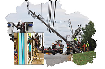
 Recognizing shock hazards can be difficult to the untrained or inexperienced eye on job sites and especially areas / facilities that have experienced storm damage. An electrocution is the result of coming in contact with a lethal amount current. Shock protection comes in many forms with ground-fault circuit interrupters (GFCIs) being that last line of defense of protection; as long as you are lucky enough that this type of protection has been installed and installed correctly. There are many ways to stay safe, we simply need to train our eyes and implement the correct procedures and tools to facilitate it.
Based on data from the National Institute for Occupational Safety and Health (NIOSH) National Traumatic Occupational Fatalities (NTOF) surveillance system, electrocutions were the fifth leading cause of death from 1980 through 1995. The 7,326 deaths caused by electrocutions during this period accounted for 7.8% of all fatalities in the workplace and averaged 488 deaths per year. Electrocutions were fifth as compared to motor vehicle incidents (#1), machine related deaths (#2), homicides (#3) and, finally, falls (#4). Yes, it is hard to protect from something you can’t see, but there are lines of defense that you can use to ensure you do not come in contact with energized conductors and/or equipment.
Based on data from the National Center for Health Statistics (NCHS), the total number of electrocutions in the United States has decreased from 670 in 1990 to 400 in 2000. This is a reduction of 40%. During this same period, an estimated number of electrocutions related to consumer products decreased from 270 to 150, a whopping 44%. The work we do in codes and standards is driving these numbers in the right direction. Product standards are making the necessary changes to ensure products are more robust with this regard, installation codes like the NEC are including changes that help to provide the protection needed in new structures being built and work practices standards like NFPA 70E help to address safety in the workplace. On top of all of this activity, we are more educated on the topic of shock protection through articles such as this and IAEI training events like those held across the country every day.
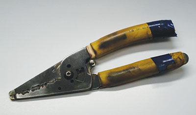
Figure 1. Electrical tape or similar methods are not a fix for these types of severe neglect.
Lines of Defense
There are many ways to avoid coming in contact with energized conductors and equipment and there are various documents that help us understand how to do just that. The primary document that comes to my mind on this topic is the National Fire Protection Association’s (NFPA) number two best seller, NFPA 70E, “Standard for Electrical Safety in the Workplace.” In addition to this document, the National Electrical Code, NFPA 70, also helps. Let’s review some important lines of defense.
Grounding and Bonding: NEC 2011’s Article 250 takes a total of 31 pages to help ensure the grounding and bonding of your system is such that equipment type ground faults have the lowest amount of impedance possible, resulting in them being high enough to be overcurrents that are cleared by the overcurrent protective devices in the circuit. Ground faults can be overcurrents if they are high enough to exceed the ratings of the conductors and other equipment. In fact, NEC 2011 Article 100’s definition of overcurrent includes ground faults; it states that an overcurrent is “any current in excess of the rated current of equipment or the ampacity of a conductor. It may result from overload, short circuit, or ground fault.” By ensuring an effective ground path, overcurrent protective devices can do their job in clearing these dangerous faults that if left unattended due to high impedances, could result in fires and even electrocutions should someone touch these energized parts. Acting to de-energize problem circuits before a person comes in contact with them or the equipment they energize helps avoid an electrocution from occurring.
Distance: Putting distance between yourself or others and a hazardous location is one sure way to prevent electrocutions. Barriers and guards can help ensure only qualified individuals are in work areas. NFPA 70E has provisions for limited approach boundaries and advises that physical mechanical barriers should be installed no closer than the restricted approach boundaries defined within that document. It’s advisable to use non-conductive barriers, especially where they may come in contact with energized parts. Tools also help to put some distance between you and the work you are performing that may present opportunities for you to come in contact with energized equipment. Tools such as communicating management systems will provide the ability to open or close protective devices or switches from the safety of an office well away from the equipment. Hot sticks and similar type devices also facilitate the separation needed. Your equipment, though, must be well maintained and inspected before every use.
Insulated Tools: Insulated hand tools, matting and other personal protection equipment (PPE) can help prevent electrocution should you or your tool come in contact with energized equipment. Ensure your tools have not fallen in to disrepair, as insulation that is there to protect you could be jeopardized. You may have hand tools with insulated handles worn through, creating safety concerns. Figure 1 is a severe case of neglect. Electrical tape or similar methods are not a fix for these types of problems. There comes a time when if your tools don’t pass basic visual inspections, they should be replaced. Some tools require more than just a visual inspection; specific testing to identified standards may be required. NFPA 70E’s Table 130.7(C)(14), “Standards on Protective Equipment,” provides reference documents for various PPE items you will use on projects.
Rubber protective products require visual inspection before every use. Table 130.7(C)(14) has the following with respect to these types of products. Rubber Protective Products — Visual Inspection Standard Guide for Visual Inspection of Electrical Protective Rubber Products ASTM F 1236 – 96(2007)
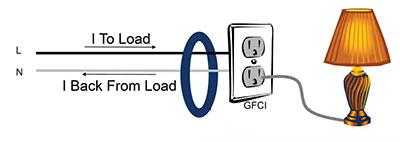
Figure 2. This drawing Illustrates that the ground-fault sensor must have both conductors passing through the device. This sensor senses an imbalance in current and sends the difference of current between that which is going to the load and that which is coming back from the load to the relaying equipment.
For even more detail on rubber insulating equipment, NFPA 70E has Table 130.7(C)(7)(c), “Rubber Insulating Equipment, Maximum Test Intervals,” yet another good example of testing frequency and reference test standards. This table advises that blankets should be tested before first issue and every 12 months thereafter. Gloves should be tested before first issue and every 6 months thereafter. Gloves are tested to ASTM F 496. This table addresses blankets, covers, gloves, line hose and sleeves.
Personal Protective Equipment: Your personal protective equipment is important on every job. You must not only maintain your PPE, but you must also ensure you are using the correct equipment for the job at hand. NFPA 70E 130.7(C)(15), “Selection of Personal Protective Equipment When Required for Various Tasks,” is the perfect reference for this line of defense. This section includes a wealth of information providing guidance on which PPE should be utilized for various types of projects. This section includes those tables illustrated above as well as hazard / risk category guidance to help convey which PPE is required when working on various types of equipment.
Working De-Energized / Lockout-Tagout: Yet one more way to ensure your team avoids electrocution is to work on de-energized equipment. We should always strive to work de-energized. Proper lock-out tag-out procedures should be followed, and effective testing techniques to ensure equipment is de-energized are important as well.
GFCI Protection: The acronym GFCI is used quite often and if I were to hazard a guess, I would say that very often it is used incorrectly. It is not only important to use terminology correctly but to also understand the limitations of the various ground-fault devices out there to facilitate in their proper application. GFCI protection is your last line of defense that is hopefully provided in your situation. The next few sections will take a high level look at a few different types of ground-fault devices.
Safety Plan: Last but not least is your safety plan. This is that document that pulls together all of your safety procedures and policies providing your plan to electrical safety. This document is your springboard for safety training and reporting. It is the glue to all that is safety for your organization.
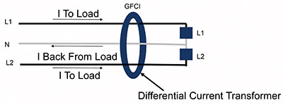
Figure 3. This image demonstrates all of the conductors passing through the sensor, as it is the job of the sensor to ensure all current is accounted for. Only 2-pole devices are adequate for these types of applications.
UL 943 vs. UL 1053 Ground-Fault Protection Devices
We’re talking people protection versus equipment protection when we set these two UL standards side-by-side. A device tested to UL 943, “Ground-Fault Circuit Interrupters,” is one that is intended for the protection of personnel. The Scope of UL 943 reads as follows: “This Standard applies to Class A, single- and three-phase, ground-fault circuit-interrupters intended for protection of personnel, for use only in grounded neutral systems in accordance with the National Electrical Code (NEC), ANSI/NFPA 70, the Canadian Electrical Code, C22.1 (CEC), and Electrical Installations (Use), NOM-001-SEDE. These devices are intended for use on alternating current (AC) circuits of 120 V, 208Y/120 V, 120/240 V, 127 V, or 220Y/127 V, 60 Hz circuits.”
A UL 1053, “Ground-Fault Sensing and Relaying Equipment,” device on the other hand is one that is designed to protect from equipment damage due to ground fault. The scope of this standard reads as follows: “These requirements cover ground-fault current sensing devices, relaying equipment, or combinations of ground-fault current sensing devices and relaying equipment or equivalent protection equipment for use in ordinary locations that will operate to cause a disconnecting device to open all ungrounded conductors at predetermined values of ground-fault current, in accordance with the National Electrical Code, ANSI/NFPA 70.” These types of devices help to prevent burn downs and other types of electrical fires.
A ground-fault device is going to be present to serve one of two basic needs: provide people protection or provide equipment protection. We’ll discuss the applications of both of these types of devices after covering some of the basics of ground-fault protection to help us understand their goals and their proper application. Suffice it to say that a device listed to UL 943 is designed for personnel protection and a device listed to UL 1053 is designed for equipment level ground-fault protection. Let’s take a quick refresher on how a GFCI device works before addressing the differences between these two basic types of devices.
Ground-Fault Device Operation Basics
A ground-fault device operates off of the basic principle of differential current; that current which goes out to the load through the hot conductor has to come back from the load over the neutral conductor. (Reference figure 2). The conductors involved are the expected paths for current. This applies to 2-wire, 3-wire or even more conductors in the case of three-phase installations. A three-phase device may appear to get a little more complicated due to phase angles and more hardware that needs to be installed, but you are still working off the basic fundamental principal of what goes out must come back over the expected paths, the conductors for the circuit.
A ground-fault device will employ two key components that work together to determine if ground-fault current is flowing. The system is comprised of sensing equipment and relaying equipment. The sensing equipment will come in the form of a current transformer that can be placed at various locations within the circuit. Sensing equipment and relaying equipment do not have to all be in one self-contained device. Industrial power systems will employ separate sensing equipment in the form of current transformers around bus bars or large conductors that must be wired back to the equipment. In the case of smaller ground-fault type devices like those you will find in residential applications, both sensing equipment and relaying equipment are located in the same small enclosure. Just to keep things simple, we’ll address what you would find in a residential ground-fault device as both of these key components are typically located within one small compact device.
Your basic ground-fault breaker or receptacle-type devices include a current transformer that surrounds the hot and neutral conductors of the circuit and a small circuit board that receives the signal from this sensor and makes the decision of whether or not to open the circuit. The conductors that pass through the sensor window must include all hot and neutral conductors serving the load. This is why, for shared neutral applications, you cannot apply a handle tie to two single-pole breakers and share the neutral. Both breakers need their own neutral return path. A two-pole GFCI device ensures the integrity of current flow through the internal current transformer for proper operation. (Reference figures 2 and 3 for examples of this).
Ground- fault currents are seeking the path of least resistance back to the source. NEC 2011’s Article 250 takes the time in a total of 31 pages to help you ensure the grounding and bonding of your system is the best it can be. For equipment ground faults, you want a low impedance path to the source. Article 250 helps get you there. Every wire connector and connection point in the grounding system is important to achieve your goals. If you have a good low impedance path to ground, your equipment type ground faults will become overcurrents that are acted upon by your standard overcurrent protective devices up stream.
Personnel Protection – UL 943
Now that we have a basic understanding of how ground-fault devices work, let’s explore what makes a ground-fault device a GFCI, one that is intended to protect personnel. To get electrocuted, three things are important: (1) the amount of current, (2) the path it takes through the body and (3) the amount of time it flows. A GFCI device does not know the path that current takes through your body and can have no control over that, but it can detect the amount of current and identify when to open the circuit. UL 943 defines these two key parameters for these types of devices. A GFCI device is designed to not trip for currents less than 4 mA and to always trip for currents above 6 mA. The amount of time it takes is determined by a couple of equations. For low-resistance faults, the equation is as follows:
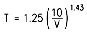
For high-resistance faults, the equation is as follows:
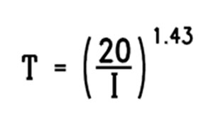
So as an example, for a high-impedance fault which would result in a small current flowing, say 6mA as an example, the GFCI device as per the above equation will take 5.59 seconds to trip.
In reality, all GFCI devices trip much faster than that required by UL 943 and a 6mA fault would normally take no more than 0.1 seconds, with some margin for error, to be cleared by an off-the-shelf GFCI device.
To understand what this means to a person, the following table is used by many documents to describe the effect of current.
A GFCI device is designed to open the circuit to avoid the problems identified in table 1.
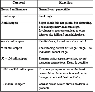
Table 1. The effect of current on humans
Equipment Protection – UL 1053
A device designed to this standard for equipment level protection is not meant to protect a person from electrocution. The UL standard for this type of device does not specify the current level at which it will pick up; it merely defines, amongst many other requirements, the amount of time it can take to clear. A UL 1053 device establishes the time criteria for clearing a ground fault at the pick-up level defined by the manufacturer of the device.
This performance criterion is not based on when the heart goes into defibrillation or when it may stop. This is an important thing to remember as it would be a mistake to apply a UL 1053 device, thinking you are going to achieve personnel protection.

Table 2. A UL 1053 device establishes the following as the time criteria for clearing a ground fault at the pick-up level defined by the manufacturer of the device.
Parting Remarks
There are many ways to prevent electrocution. Leverage your various lines of defense to avoid coming in contact with energized conductors and/or equipment; and as your last line of defense, ensure you have employed the correct GFCI device for personnel protection. GFCI devices are not required on every circuit at every voltage and for every application. Do everything you can to keep your distance, use insulated equipment, take care of your tools, and think and observe before proceeding in and around hazardous areas.
As always, keep safety at the top of your list and ensure you and those around you live to see another day.