Up until now, I have been talking about dc, direct current, in which the current in the circuit travels in one direction. Batteries and other sources of dc are marked with what we call polarity marks, + and –. When a battery is connected in a circuit, the current comes out of the positive (+) end of the battery and returns to the battery at the negative (–) end. This is true for all sources of dc. If we connect the test leads of a volt ohm meter (VOM) to a battery with the red colored positive (+) lead connected to the positive end of the battery and the black negative (–) lead connected to the negative end of the battery, the voltage reading on the display will be positive. Most VOMs do not display a plus sign (+) for positive readings but they do display a negative sign (–) for negative readings. If we swap the leads by connecting the red lead to the negative end and the black lead to the positive end, the VOM will display a negative voltage. For loads, elements of a circuit that use electricity, the voltage that appears across a load is positive at the terminal in which current enters the load and negative at the terminal where the current exits the load (see diagram 1).
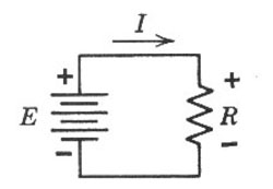
Diagram 1. For loads, elements of a circuit that use electricity, the voltage that appears across a load is positive at the terminal in which current enters the load and negative at the terminal where the current exits the load.
Alternating Current
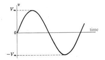
Diagram 2. Alternating current is often pictured graphically by this diagram. This graph of voltage versus time is often called a sine wave.
The other type of current is called ac, alternating current. In alternating current, the magnitude and polarity of the voltage and current are continuously changing. At one instant in time the current flows in one direction. A moment later, the current flows in the opposite direction. Alternating current is often pictured graphically by diagram 2, a graph of voltage with respect to time. This graph of voltage versus time is often called a sine wave.
For most electric power sources in the U.S., the frequency is 60 cycles-per-second or 60 Hertz. That means that the voltage and current complete a complete cycle sixty times per second. Looking at diagram 2, the voltage starts off at 0 magnitude. The voltage increases with time until it gets to a maximum and then decreases with time until it gets back to 0. During this first half cycle, the current flows in one direction. Then the current reverses and the voltage increases back up to a maximum and then decreases back down to 0. In this second half cycle, the current flows in the opposite direction. At this point, 1/60 of a second or 16 2/3 milliseconds have passed. The voltage reverses and starts the next cycle identical to the first cycle. When ac was first generated, it was difficult to measure the voltage of the ac source without an oscilloscope. An oscilloscope is an instrument that looks like a miniature television set that is used to display voltage waveforms. Oscilloscopes are frequently used in hospitals to display the human heart beat. The oscilloscope shows a graph of the voltage very similar to diagram 2. In the example pictured in diagram 2, the maximum voltage Vm is the peak voltage. How does this peak voltage of an ac source relate to dc voltage? This was a question Thomas Edison and other early electric power inventors asked over a hundred years ago. To answer the question, they applied a dc voltage of known magnitude to a known resistance and recorded the amount of heat given off by the resistance. They then applied an ac voltage of known peak voltage to the same resistance. They adjusted the ac voltage until the amount of heat generated by the resister was the same.
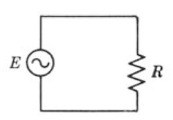
Diagram 3. AC sources in electrical diagrams are often pictured as a sine wave inside a circle.
They found by experimentation that the equivalent dc voltage of an ac voltage was the peak voltage divided by the square root of 2. What was later to be called effective voltage was 0.707 x Vm , where 0.707 is 1 / √ 2 . The effective value is now called the root mean squared (RMS) value. I’m not going to get into the mathematical derivation of RMS. When we use a modern VOM to measure ac voltage, the meter reads volts RMS. What is important to know is that a 120-volt, 100-watt light bulb will produce the same heat and light magnitude whether it is energized from a ac source supplying 120 volt RMS or a bank of batteries supplying 120 volts dc. AC sources in electrical diagrams are often pictured as a sine wave inside a circle (see diagram 3).
Measuring Large Magnitude Currents
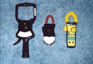
Photo 1. Left: Columbia “Tong-Test” 1000 amp ammeter (vintage?). Center: Weston 600 amp Amprobe ammeter and voltmeter (vintage?). Right: Ideal model #61-766 600 amp “Clamp Meter” digital multi-meter (vintage 2004)
There are two methods for measuring high magnitude currents in a circuit. The clip-on ammeter is the easiest method for spot-checking current in cables. Photo 1 shows some examples of clip-on ammeters. The advantage of the clip-on ammeters is that the circuit does not have to be modified to measure the current. By squeezing the lever on the side of the ammeter, the jaws open. We place the jaws around the cable and then release the lever. If the jaws do not close completely, the meter will not measure the current accurately. Note the size of the window created by the jaws when purchasing a clip-on ammeter. To measure the current in large conductor cables or small cables with thick insulation will require a large window ammeter.
Current Transformers
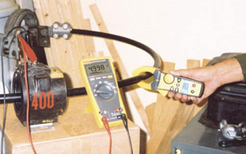
Photo 2. A General Electric model JAKO 400:5 amp. CT (left) connected to a Fluke model 175 VOM (center). The VOM is measuring the current at the secondary terminals of the CT. If safety is a concern, note the voltage is only 4 volts.
The other method is to use a current transformer often referred to as a CT. A current transformer looks like a large donut (see photo 2). The current transformer transforms high currents to low currents. The circuit in which the current is to be measured must be routed through the donut hole of the CT. There is a pair of terminals on top of the CT. These are the secondary terminals. A low current, usually 0’5 amp ammeter must be connected to these terminals. The large number painted on the side of the CT is part of the CT ratio. Thnameplate on the side of the CT gives the ratio for the CT. A CT with a ratio of 400 to 5 means that when 400 amps are flowing in the conductor that passes through the CT donut hole, 5 amps will pass through the secondary terminals of the CT. In the case of a 400 to 5 amp (400:5) CT, the manufacturer will paint “400” on the side of the CT. 600-volt insulated CTs are available in ratios up to 6000:5. Some CTs are available in dual ratio. Photo 2 shows a General Electric model JAKO 400:5 amp. CT (left) connected to a Fluke model 175 VOM (center). The VOM is measuring the current at the secondary terminals of the CT.
The reading on the VOM is 4.998 amps. The current in the test circuit is 4.998 times the CT ratio. The CT ratio is 400 / 5 = 80.
4.998 x 80 = 399.8 amps
Photo 2 also shows an Ideal 600 amp multimeter (right). Note the reading on the multimeter is 399 amps. î”e accuracy of the CT/VOM combination is usually better than the clip-on ammeter but the CT is a pain to use because the circuit must be routed through the CT.
CT Shorting Bar
When you receive a CT from the manufacturer, you will find a shorting bar connecting the secondary terminals of the CT together. The bar should be removed only after the low current ammeter is connected to the terminals. Some shorting bars don’t have to be removed. They can be rotated 90 degrees so that they are no longer shorting the terminals. The circuit in which a CT is wired should never be energized without the low current ammeter connected to the CT secondary terminals or the shorting bar in place. This is a safety issue! The CT can produce high voltage on the secondary terminals if this rule is not followed.
CT Rating Factor
CT rating factor lets us know the maximum current the CT can handle. For some CTs, the maximum current is the higher number of the ratio. For those CTs, the rating factor is 1. The General Electric JAKO 400:5 amp CT in photo 2 has a rating factor of 4. The maximum current the CT can handle is 4 x 400 = 1600 amps. Note that if you want to measure currents up to 1600 amps with this CT, the low current meter you connect to the secondary terminals of the CT must be capable of measuring current up to 4 x 5 = 20 amps.