Energy
In Part 2, I discussed power. A light bulb rated at 100 watts and 120 volts will use 100 watts of power when operating at 120 volts. If I wanted to operate ten 100-watt light bulbs on a gasoline powered generator, the rated power output of the generator would have to be at least 1000 watts. The rated horsepower of the gasoline engine that runs the generator is related to the rated power output of the generator. Energy is power times time. Electrical energy is usually measured in watt hours abbreviated Wh, kilo-watt hours abbreviated kWh, and mega-watt hours abbreviated MWh. If we operate ten 100-watt light bulbs for 24 hours, we would have used 1000 watts X 24 hours = 24,000 Wh or 24 kWh of energy. The amount of gasoline consumed by the generator is related to the amount of energy delivered by the generator.
The watt-hour meter
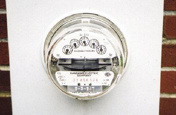
Photo 1. Watt-hour meter
The mechanical watt-hour meter on the side of your house is a very accurate instrument for measuring energy. The heart of a typical mechanical watt-hour meter is a specially designed electric motor. The motor’s speed is directly proportional to the product of the voltage and the current. If you would like to know how much power is flowing through the watt-hour meter at any point in time, just time how long it takes for the disc to rotate one revolution. The disc is located in the center of the meter rotating on a vertical shaft. If the disc is rotating rapidly, it is sometimes easier to time how long it takes the disc to rotate ten times. There is a black mark at one point on the edge of the disc to help you count the number of revolutions. After you have determined how long it takes for the disc to rotate one revolution in seconds, calculate how many revolutions it would make in an hour by dividing 3600, the number of seconds in an hour, by the number of seconds for one revolution. Next, look at the nameplate of the meter. On the nameplate you will find Kh followed by a number.
Multiply this number by the number of revolutions per hour. That will give you the power in watts being served through the watt-hour meter. Let’s try some examples. If one revolution of the disc takes 50 seconds, to calculate how many revolutions in an hour, divide 3600 by 50 and you will get 72. The Kh for my watt-hour meter at my house is 12. We multiply 72 times 12 = 864 watts. My heater blower, some lights and my computer is on. If the disc was rotating fast and you counted ten revolutions in 20 seconds, the time for each revolution is 20 divided by 10, or 2 seconds. The number of revolutions in an hour is 3600 divided by 2 = 1800. If the Kh is 12, the power is 1800 x 12 = 21,600 watts or 21.6 kW. A load of this magnitude in a normal size house would not happen every day unless the house has electric heat.
Source resistance
In Part 4 of this series, we assumed the source voltage at the outside receptacle was 120 volts and we calculated what the voltage would be at a shed some 100 feet away from the house. We were attempting to heat the shed with a 1500Welectric heater on the end of a 100 foot extension cord made with 18 AWG copper wire. The assumption that the source voltage was constant at 120 was not realistic. In reality, the voltage at the receptacle will not stay constant because there is a lot of resistance between the source transformer and the receptacle. There is also some resistance within the source transformer. So how much resistance are we talking about? Let’s assume the wire between the receptacle and the load center is fifty feet of 14 AWG copper. The resistance of 14 AWG copper wire is 2.52W/ 1000 feet. For fifty feet, the resistance is 0.126Win each conductor. Since there are two conductors, we multiply this resistance by two to get 0.252W. Let’s assume the service-entrance cable is 25 feet of 2/0 AWG aluminum. The resistance of 2/0 AWG aluminum is 0.128W/1000 feet. For 25 feet, the resistance is 0.0032Win each conductor. Since there are two conductors, we multiply this resistance by two to get 0.0064W. Let’s assume the aerial service to the house is eighty feet of 1/0 AWG aluminum triplex with a 2 AWG aluminum neutral. The resistance of the 1/0 AWG aluminum phase conductors is 0.161W/1000 feet. For eighty feet, the resistance is 0.1288W. The resistance of the 2 AWG aluminum neutral is 0.256W/1000 feet. For eighty feet, the resistance is 0.02048W. Since there are two conductors, one phase and one neutral, we add these resistances together to get 0.03336W.
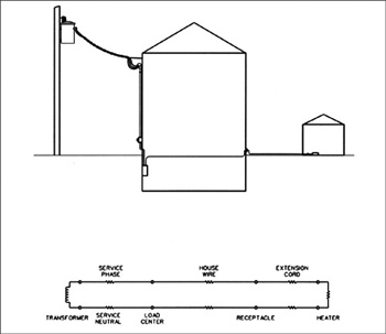
Figure 1. Circuit diagram shows only three resistances between the source transformer and the heater, service, house wiring and extension cord.
Note that figure 1, the circuit diagram, shows only three resistances between the source transformer and the heater, service, house wiring and extension cord. The service resistance is the sum of the aerial service resistance and the service-entrance cable resistance. As we did in Part 4, we apply Kirchhoff’s voltage law to the circuit. For this circuit, the voltage at the heater is equal to the source voltage minus the voltage drop in the service, minus the voltage drop in the service-entrance cable, minus the voltage drop in the house wire, minus the voltage drop in the extension cord. This time we assume the source voltage at the transformer is 120 volts. The voltage at the heater is:
V = 120 – ((0.03336Wx I) + (0.0064Wx I) + (0.252Wx I) + (1.278 x I))
Since the conductor resistances are each multiplied by the current I, we can consolidate the equation to:
V = 120 – ((0.03336 + 0.0064 + 0.252 + 1.278) x I)
V = 120 – (1.56976 x I)
You will recall from Part 4, we found from testing that for this electric heater, the relationship between the heater current I and the heater voltage V was:
I = (0.0976 x V) + 0.45
By combining these two equations, we can solve for the circuit current I and the heater voltage V.
V = 120 – (1.56976 x ((0.0976 x V) + 0.45))
V = 120 – (0.15320 x V) – 0.7063
V = 119.2937 – (0.15320 x V)
Adding (0.15320 x V) to both sides of the equation we get:
V + (0.15320 x V) = 119.2937
1.15320 x V = 119.2937
If we divide both sides of the equation by 1.15320 we get:
V = 119.2937 / 1.15320
V= 103.44 volts
The circuit current I = (0.0976 x V) + 0.45 = (0.0976 x 103.44) + 0.45 = 10.54 amps. Note that the calculation in Part 4 determined the heater voltage to be 106.18 volts. A more correct voltage is 103.44 volts.
Source voltage variation
In this calculation, we assumed the voltage at the transformer was 120 volts. Is that reasonable? For residential 120/240-volt service, most utilities are required by law to serve the customer at the service point within 5 percent of normal voltage. This means the phase-to-neutral voltage at the service point must be between 114 and 126 volts.
The phase-to-phase voltage must be between 228 and 252 volts. In the above calculation, the voltage at the service point is 120 volts minus the voltage drop in the service or 120 – (0.03336Wx 10.54 A) = 119.64 volts. If the voltage at the service point were only 114 volts, the voltage at the heater would be less than one hundred volts and the heater would be producing even less heat. Utilities try to regulate their primary line voltages to maintain the customer’s service voltage within the range dictated by law.