Series combination ratings are utilized to attempt to save money on some jobs. This article presents a simple checklist that can be completed by the contractor and/or designer when series rated combinations are proposed. The checklist is designed to be a single sheet that is double sided. The front side requires information for a specific series rated application. The backside provides an easy reference of general application information and provides the specific National Electrical Code requirements. In the plan review stage, the checklist provides the AHJ the necessary information to review series combinations in their specific application. During the inspection phase of the installation, the AHJ can use this checklist as a guide to confirm compliance with the design and proper installation requirements.

Figure 1. Fully-rated fuse system
There is confusion in the industry on the requirements of properly applying and installing series combination ratings. What combinations are suitable? In the specific building installation, is the series combination rating greater than the available short-circuit current? Is the motor contribution within allowable limits? Is the panelboard or switchboard properly marked by the manufacturer for the series combination rated devices that are to be used? Has the installer properly affixed the required field markings? Are there selective coordination requirements that would not permit using series rated combinations? If these questions are not investigated and found to be acceptable for a specific application, then the series rated combination cannot be used. After a job is designed with fully rated fuses or circuit breakers, sometimes the job is value engineered and series rated combinations are proposed for portions of the system. It is important to insure that the design still meets the NEC. This checklist can help that process.

Figure 2. Fully-rated CB system
A fully rated system is one in which all of the overcurrent protective devices have an individual interrupting rating equal to or greater than the available short-circuit current at their line terminals. This is a requirement in 110.9. Fully rated systems can consist of all fuses, all circuit breakers, or a combination of fuses and circuit breakers (see figures 1 and 2).
Series rated is a combination of circuit breakers or fuses and circuit breakers that can be applied at available short-circuit levels above the interrupting rating of the load side (protected) circuit breaker, but not above the interrupting rating of the main or line-side device. A series rated combination can consist of fuses protecting circuit breakers, or circuit breakers protecting circuit breakers. It is very important to note that with a series rated combination there is an allowance per 240.86 to permit application of a load side (protected) circuit breaker beyond its individual interrupting rating. Figure 3 illustrates a fuse/circuit breaker series rated combination. Figure 4 illustrates a circuit breaker/circuit breaker series rated combination.

Figure 3. Illustrates a fuse/circuit breaker series rated combination
From an inspection perspective, the first priority is to focus on compliance to 110.9. The most suitable application for series rated combinations is for branch circuit, lighting panel circuit breakers. With a series rated combination, the load side circuit breaker is applied beyond its individual interrupting rating. Because of this, if a series rated combination is to be used, the designer and contractor should select the tested, listed and marked line-side protection that will assure reliable performance over the lifetime of the electrical system. If the line-side protecting overcurrent protective device does not react as intended due to lack of maintenance or loss of calibration, the load-side circuit breaker may be on its own to interrupt. Although series rated combinations save a small percentage of the initial equipment costs, there are many issues about designing and utilizing series rated combinations. However, that is another article topic targeted at the designers and contractors. This article is focused on the NEC compliance requirements for series rated combinations.

Figure 4. Figure 4 illustrates a circuit breaker/circuit breaker series rated combination
A nationally recognized testing laboratory (NRTL) does not list a fuse/circuit breaker or circuit breaker/circuit breaker series combination by itself. The listing for a series combination has to be evaluated and found suitable for a specific manufacturer’s panelboard, loadcenter or switchboard line.
Basically, it works like this. A specific type circuit breaker (XYZ) by Best CB Company is tested as the load-side (protected) circuit breaker with a specific line-side (protecting) overcurrent protective device, which can be either a circuit breaker or fuse. For instance in figure 3, the 20-amp XYZ circuit breaker by Best CB Company is tested with a 400-amp Class J fuse (a special umbrella fuse is used to insure the let-through represents the 400 A Class J fuses as made by all manufacturers). The short-circuit test is at 200,000 amperes even though the XYZ circuit breaker has an interrupting rating of 10,000 amperes. Based on UL 489, Standard for Molded-Case Circuit Breakers, if the circuit breaker passes the evaluation criteria, the combination of a 400-amp Class J fuse and the 20-amp XYZ circuit breaker manufactured by Best CB Company is filed by the NRTL as only a recognized series rated combination (see figure 5). However, this is not a listing, further evaluation is necessary.
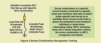
Figure 5. Series combination recognition testing
To be useful, the panelboard or switchboard manufacturer (XYZ Panelboard Manufacturing Company) must have their equipment tested, evaluated and listed by a NRTL using the recognized combination in their panelboard or switchboard (see figure 6).
If this recognized series combination passes the NRTL’s evaluation, then this series combination of load-side 20-amp XYZ circuit breaker by Best CB Company and line-side 400-amp Class J fuses is marked on that specific manufacturer’s style panelboard or switchboard (referred to as tested, listed and marked). The load-side (protected) circuit breaker would be installed in that panelboard or switchboard. The line-side (protecting) Class J fuses, up to 400 A, could be in that panelboard or switchboard or in another upstream panelboard or switchboard. And now the XYZ circuit breaker manufactured by Best CB Company, which has a 10,000 A interrupting rating, installed in XYZ Panelboard with the series rated combination mark, can be applied on a system with 200,000 amperes available short-circuit current (see figure 7). That is, if other NEC® requirements are met! These other requirements are extremely important to make sure a series rated combination is, in fact, applied per its testing, listing and marking [110.3(B)].
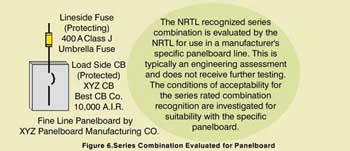
Figure 6. Series combination evaluated for panelboard
240.86(A) Factory Labeling Requirement. The process of testing, listing and marking a series rated combination was just covered. Section 240.86(A) requires that, when a series rated combination is used, the switchboard or panelboard be listed and factory marked for use with the series rated combinations to be utilized. Often there is not enough room in the equipment to show all of the legitimate series rated combinations. So UL 67, Panelboards, allows for a booklet to be referenced and supplied with the panelboard. The booklet is to be affixed to the panelboard. These booklets typically provide all of the acceptable combinations for the panelboard. This provides evidence that a switchboard or panelboard is listed up to a specified available short-circuit current for a specific series combination in that specific panelboard or switchboard. For a specific job, the AHJ must be provided data to demonstrate that the series rated combination has an adequate series (interrupting) rating for the available short-circuit current at the installation point of the load side (protected) circuit breaker. See figure “110.22 & 240.86(A) Labeling” on the second page of the checklist.

Figure 7. Series-rated combination NRTL listed with panelboard
This section places responsibility on the installer (electrical contractor) to affix labels on the equipment enclosures, which note the interrupting rating of the series rated combination and call out the specific replacement overcurrent protective devices to be utilized. If the upstream overcurrent protective device protecting the downstream circuit breaker is in a different enclosure, then both enclosures need to have field-installed labels affixed and call out the other location on the labels. See figure labeled “110.22 & 240.86(A) Labeling” on the second page of the checklist.
This field marking is critical for ensuring that proper devices are installed as initially intended and properly replaced years later. It becomes absolutely necessary when replacement of fuses or circuit breakers is needed; this field marking helps ensure that the original system design integrity is maintained. If the wrong replacement circuit breaker is used on the load side or line side or the wrong fuse is used on the line side, the series rating is no longer valid. This could result in a serious fire and safety hazard.

Figure 8. Motor contribution limitations of series combinations
These labeling requirements are also very important for evaluating the suitability of this equipment, if at a future date the electrical system is changed or upgraded. Proper labeling per 240.86(A) and 110.22 provides a means to assess the suitability of the series rated combination when the electrical system parameters later change due to a refurbishment or other system change. The owners or maintenance contractors should maintain these labels throughout the life of the equipment. When electrical system upgrades occur, without this labeling affixed to the equipment, the owner most often must needlessly throw out the existing equipment and buy new equipment.
Where motors are connected between the line-side (protecting) device and the load-side (protected) circuit breaker, 240.86(B) has a critical limitation on the use of series rated combinations. This section requires that a series rated combination shall not be used where “the sum of motor full-load currents exceeds 1 percent of the” load side (protected) circuit breaker’s individual “interrupting rating” [italics added.] The reason is that when a fault occurs, running motors momentarily contribute current to the short-circuit (usually about four to six times their rating). This added motor contribution could result in a short-circuit current in excess of what the load-side (protected) circuit breaker was tested to handle per the series rated combination testing, listing and marking. See the figure on motor contribution on the second page of the checklist.
This is one of the major reasons that series rated combinations are generally recommended only for lighting panel applications. Lighting panels generally do not have significant motor loads so the motor contribution is typically not an issue. However, series rated combinations used for power panel or main/feeder applications can pose a problem upon initial installation or if the loads change in the future. On a new installation with a 1000-A service load containing 50 percent motor load (which is motor full load amperes of 500), the motor contribution could be an issue in selecting a series rated combination. If a main/feeder series rating were to be considered, the feeder could require at least a 50,000-A individual or stand-alone interrupting rating (1 percent of 50,000 = 500). See figure 8 to illustrate this example.
Then consider the uncertain future of building spaces. For instance, many building spaces by their nature inherently incur future changes, such as strip malls, enclosed malls, business park buildings, manufacturing facilities, many institutional buildings, and many commercial spaces. A properly designed and initially installed series rating could be negated if the building loads change to significantly higher motor loads.
Inherently, series rated combinations cannot be selectively coordinated. The line-side (protecting) device must open at the same time and in conjunction with the load-side (protected) circuit breaker. This means that the entire panel loses power because the device feeding the panel must open under medium- to high-level short-circuit and ground-fault conditions.

Figure 9. Selective coordination limitations of series combinations
Therefore, in health care facilitates where selective coordination of ground-fault protection is required between the main and feeders, series rated combinations do not meet the 517.17 requirements. Also, series rated combinations do not meet the selective coordination requirement for elevator circuits per 620.62 where there are two or more elevators. Series rated combinations reduce emergency circuit overall system reliability as presented in the 700.25 FPN because of their limitation of fault current coordination (see figure 9).
In summary, there are specific NEC requirements that shall be met by the designer and installer if series rated combinations are to be used. The AHJ may require the designer and/or contractor to complete this checklist if a series rated combination is to be used. An electronic copy of this checklist can be downloaded from www.bussmann.com under “Application Info / NEC®/IAEI Information.”