The journey of incident energy reduction in the National Electrical Code (NEC) is one that dates back as far as 1971 when ground-fault protection of equipment (GFPE) requirements for service-entrance equipment was introduced. Let us take a look at the path that GFPE has taken in the NEC to understand the associated driving factors.
Ground-fault protection of equipment (GFPE) first entered the NEC in 1971. This was the first (but not the last) introduction of technology to address incident energy. The focus was on service-entrance equipment. The problem was massive destructive forces of arcing ground faults occurring in that service-entrance equipment. There were three basic design changes occurring at this time that drove the need for additional protection:
1. Ungrounded to grounded systems. The industry was moving from ungrounded delta systems to solidly grounded systems. Ground-fault currents were of magnitudes. NEC GFPE requirements impact solidly grounded systems.
2. 208- vs. 480-volt systems. System voltages were also increasing. Arcing faults in lower-voltage systems self-extinguish, while in higher-voltage systems arcs can be sustained causing increased damage.
3. Increased service ampere ratings. Service equipment moved from an average of 600 A to as high as 4000 A. Overcurrent protective devices with trip curves permitting longer delays at higher currents were in common use.
In a 1972 Institute of Electrical and Electronics Engineers (IEEE) paper, an author noted:
“It is the energy of this arc which releases a tremendous amount of heat in an extremely short time. The surrounding air heats up, building up pressures which blow open doors, and cause copper or aluminum buses to be melted away in a matter of seconds or less. Most surprisingly, this large amount of energy is released at fairly low current levels. The usual phase-overcurrent direct-acting trips may not always sense these low-level arcing faults within a reasonably short time. It is therefore appropriate to gain an understanding of the current limiting effects of arcing faults.”1
Forty-seven years have passed since the introduction of GFPE for service-entrance equipment in the NEC to solve a problem that we know significantly more about today than ever before (especially when one considers all the work and research on incident energy calculations for arcing faults).
What is GFPE?
GFPE is a technology that works on a fundamental principle — the current supplied on a circuit must stay within the intended path, and if current leaves the intended path going to ground it will be detected and cleared. Two important parameters of GFPE must be understood:
1. Pickup value. Each GFPE device will have a setting that is adjustable or fixed, establishing a level of current beyond which the device will begin to react. Pickup values of devices with a fixed pickup are determined by the manufacturer. Pickup values for those that are adjustable are established by the designer and installer.
2. Clearing time. Each GFPE device will have a setting that is adjustable or fixed that establishes the amount of time that the ground fault is permitted to flow. Clearing times for devices with fixed settings are determined by the manufacturer. Clearing times for those that are adjustable are established by the designer and installer.
GFPE products are listed to UL 1053, Standard for Ground-Fault Sensing and Relaying Equipment.
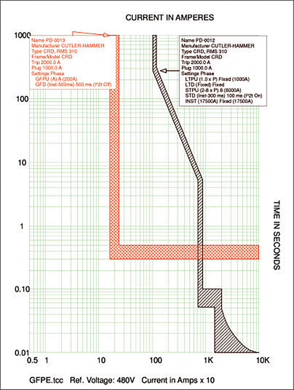
The time-current characteristic (TCC) curve of Figure 1 shows a 2,000 frame, 1,000 A Trip (2,000AF/1,000AT) circuit breaker that is equipped with GFPE set to open for ground-fault currents greater than 200 A and a maximum clearing time of 500 milliseconds (0.5 seconds) or 30 cycles.
The GFPE trip curve is represented by the “L-shaped” curve in Figure 1. Per this curve, the GFPE device will detect ground-fault currents greater than 160 A, as its pickup set point is 200 A with a tolerance of +/- 20 percent. The maximum clearing time for ground-fault currents greater than 241 A is 500 milliseconds (0.5 seconds) or 30 cycles. Any ground-fault downstream of this device can trigger it to open as long as the ground-fault current level, in the case of Figure 1, is greater than 160 A. This fact has caused many of these devices located at a facility main to be set to their maximum settings permitted by the NEC to avoid unwanted tripping due to downstream events.
The other trip curve of Figure 1 is that of the circuit breaker to which GFPE is equipped. The curve shows how it provides overload and short-circuit protection for the conductors and equipment it protects. It is important to remember that this standard overcurrent protective device can also respond to ground-fault currents high enough that they are in the faster clearing time regions of the curve.
Historical perspectives
Research around arcing ground faults, what we now know as incident energy, extends back to 1948 when C. F. Wagner, together with L. L. Fountain, authored an IEEE paper titled Arcing Fault Currents in Low-Voltage A-C Circuits.2 Research and development were rekindled in the 1960s due to the engineering practice changes noted above. Regarding discussions of arcing events in service entrance equipment, in 1960 Mr. Raczkowski from Westinghouse noted about the paper that:
“There is, however, another solution to this problem, which the author’s organization is working on: The use of a current transformer tripping device for ground protection. A zero sequence current transformer or, as in the case of a transformer secondary breaker, a current transformer in the transformer neutral feeds directly into a coil wound on the center pole of the breaker trip device. The two other series trip devices provide phase protection, and the middle one, which can have a different characteristic (long delay, instantaneous or short delay) and which can be set much lower, provides fast and sensitive ground protection. No ground relay is required. There are no panel space problems and no separate source of tripping energy is required.”3
In 1971, with GFPE solutions on the market, the text of Figure 2 was added as 230-95 giving GFPE a place in the history of the NEC. The submitter of the successful public input was the National Electrical Manufacturers Association (NEMA). The following substantiation obtained from “PREPRINT” of the Proposed Amendments for the 1971 National Electrical Code:
“The purpose of this proposal is to require ground-fault protection for low-voltage electrical distribution systems in order to minimize chances of injury of personnel and reduce damage to equipment.
“Conventional overcurrent protective devices properly selected in the light of the system of available short-circuit current provide sound equipment protection in the case of normal overloads and low impedance faults such as phase-to-phase and bolted faults. However, high-impedance faults such as arcing-to-ground are more prevalent than bolted faults. In grounded electrical distribution systems, these faults may start phase-to-phase fault, if not interrupted immediately by circuit overcurrent protection, will usually quickly become a phase-to-ground fault also. These high-impedance (low-current) faults can cause serious equipment damage before the overcurrent protective device functions.
“This delay greatly increases the risk of injury to personnel. There has been an increasing number of major service equipment damage due to line-to-ground arcing faults. Therefore, ground-fault protection, which can be set to function on ground-fault currents too low to actuate the tripping elements of the service overcurrent devices, is needed on low-voltage distribution systems.
“During the past several years, at least five major cities have reported major electrical equipment damage and in two instances fatalities have occurred in which low-fault currents have persisted for a sufficient time to cause very extensive damage. Test reports, engineering papers and discussions have made it very evident that conventional overcurrent protective devices cannot be expected to interrupt low-value fault currents ‘relative to the overcurrent ratings’ without having extensive damage to electrical equipment and possible major injury to personnel.”
Exceptions to GFPE
Over the years, exceptions were introduced into the NEC and two areas of vulnerability of GFPE were being discussed including the following:
1. Unwanted tripping: Ground-faults at various levels within the power distribution system have and still do cause the main GFPE protective devices to open. It is argued in many cases that downstream OCPDs could provide protection as these low-level ground-faults would be detected.
2. Performance: Delay times permitted by the NEC (no time limit for currents less than 3,000 A and a maximum of 1 second for currents beyond 3,000 Amps) have led to questions of whether or not protection was indeed being provided at service-entrance equipment given the wealth of knowledge around arcing faults. It’s all about current and time.
The tripping issues generated code exceptions and additional requirements in the NEC as well as in design practices. Some of the exceptions added to the NEC include the following:
• Continuous industrial processes: Exceptions were added and remain within 210.13, 215.10, 230.95, and 240.13 for those installations where a non-orderly shutdown of a continuous industrial process could introduce additional or increased hazards.
• Article 695 Fire pumps: Requirements of Sections 240.13 and 695.6(G) prohibit the use of GFPE in any fire pump power circuit.
• Article 700 Emergency systems: For these systems, GFPE was made an option and not a requirement. Provisions were included to require indication of a ground fault when GFPE protection is not provided.
• Article 701 Legally Required Standby Systems: For these systems, GFPE was made an option and not a requirement in a similar manner to Article 700 systems. Provisions were included to require indication of a ground-fault when GFPE protection is not provided.
• Article 517 Health Care Facilities: Health care facility requirements, in Section 517.17 of NEC 2017, increases the number of layers of GFPE protection so that selective coordination of these OCPDs is possible to limit outages should a ground-fault occur downstream. In addition, this Section prohibits the additional levels of ground-fault protection from being installed on the load side of an essential electrical system transfer switch.
Moving GFPE closer to the load
GFPE has found an effective way to address problems but not cause complete system outages. The placement of GFPE to detect and isolate problems in equipment closer to the load has been found to provide value in two ways.
1. The problem specific load is isolated and cleared without impact to the rest of the system. This eliminates the tendency of increasing trip current thresholds and clearing time settings, which leave the system with little to no protection.
2. Isolation of a problem circuit can help prevent shock as equipment becomes energized and very low levels of current flowing through unintentional energized equipment are not permitted to persist.
The first instance of placing GFPE to solve a specific problem downstream in the system occurred when NEC 1987 introduced Section 427.22 which mandated ground-fault protection of equipment for electric heat tracing and heating panels. The submitter for this requirement noted that electrical resistance heaters that have electrical insulation failures, when not disconnected, generate leakage currents and arcing that have caused ignition of cable or surrounding materials. These failures expose personnel to shock hazards until they are de-energized. The standard overcurrent protective devices at this level in the circuit were not responding to these low-level destructive ground faults.
Next, it was NEC 1993 that introduced 426-53, which we now know as Section 426.28. This requirement mandated GFPE for fixed outdoor electric deicing and snow-melting equipment. The submitter noted that great quantities of self-regulating heat tape was being used for gutter and downspout de-icing and posed a similar hazard to those products used for Article 427 applications. It was the same hazard (almost), but no protection rule.
Finally, we see activity around GFPE in marinas as the hazard of energized exposed equipment takes more lives in this area. Article 555 has and continues to see attention around providing the value of GFPE for these specific applications. The objective is to detect problems and clear the problem circuits before someone can come in contact with energized components. The issue in this application is not the destructive forces of arc flash or fires due to arcing and sparking. The debates in this area continue to be similar to those had when GFPE was required for service- entrance equipment. Unwanted tripping is yet again the concern and will be the area of discussion as Code Making Panel 7 reviews the GFPE requirements, public inputs and comments in Article 555.
Closing remarks
GFPE has been used historically in the NEC to solve two types of issues within a power distribution system:
1. High energy arcing ground faults that result in catastrophic failure of service-entrance equipment (arc flash hazards).
2. Low magnitude leakage currents that can persist for long periods of times causing the threat of fires and shock due to low level arcing to ground and unintentional energization of exposed equipment.
When placed at high up in the system, GFPE can present challenges to strike the balance between protection and reliability. GFPE can be an effective tool to mitigate hazards but we must understand the technology, the application, and the hazard to ensure it is the right technology applied in the right location.
As always, keep safety at the top of your list so you and those around you live to see another day.
References
1. Dunki-Jacobs, J. (1972). The Effects of Arcing Ground Faults on Low-Voltage System Design. IEEE Transactions on Industry Applications, (pp. Vol. IA-8)
2. Wagner, C. F., & Fountain, L. L. (1948). Arcing Fault Currents in Low-Voltage A-C Circuits. AIEE Transactions, (pp. Vol. 67 pp. 166-174)
3. Kaufmann, R. H., & Page, J. C. (1960). Arcing Fault Protection for Low-Voltage Power Distribution Systems – Nature of the Problem. Transactions of the American Institute of Electrical Engineers. Part III: Power Apparatus and Systems ( Volume: 79, Issue: 3), (pp. 160 – 165)
Thomas A. Domitrovich is an Electrical Engineer within Eaton’s electrical group with experience in engineering, sales & marketing, business development and product management. Domitrovich is actively involved with various electrical industry organizations and most recently focuses on the continued growth of electrical safety. Domitrovich is an author with a wide range of trade magazine articles including columns in two industry trade magazines focused on electrical safety.
He sits on NFPA Code Making Panel 2 for the continued development of the National Electrical Code (NFPA 70). He is also on the NFPA committee for the continued development of NFPA 73 and chairs various committees for other electrical industry organizations. Domitrovich is a LEED© Accredited Professional, a licensed Professional Engineer and holds a Bachelor of Electrical Engineering from Gannon University.