
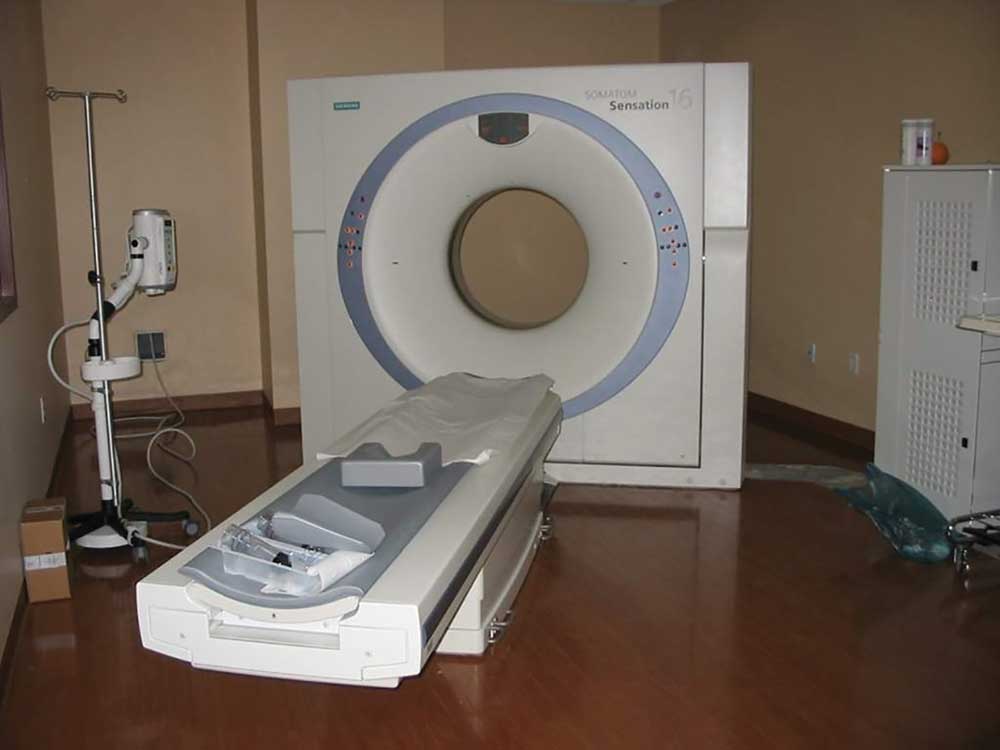
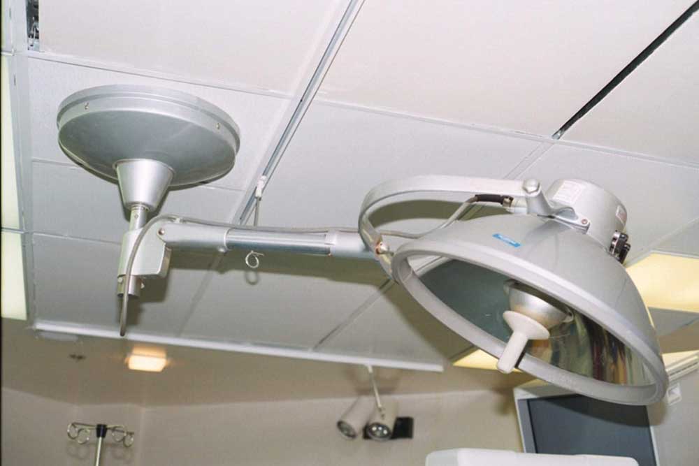
One of the most challenging electrical installations for any electrical contractor, electrician, and electrical inspector is one involving health care. From health care centers in pharmacies to major health care hospitals, anyone who is not intimately familiar with the intricacies of medical headwalls, major electrical equipment [such as cardiac catheterization, cat scans, magnetic resonance imagining (MRI)], or even just the installation and supply of operating lights, is in for a real lesson in humility. For example, small mistakes at the offset of the installation of a medical headwall at rough-in or the support structure for a catheterization machine can be extremely costly when it comes time to trim the units after the final drywall installation. An MRI installation requires an understanding of the electrical equipment with high frequency and extremely high magnetic effects in the area surrounding the machine. The interconnection between the MRI unit where the patient resides and the operator in an adjacent room requires major knowledge for both rough-in of the equipment, as well as final connections.
This article covers the theory behind the safety procedures necessary for these installations so the patient, the nurses, the doctors, and all others in close proximity will not be subject to spurious electrical currents and other similar hazards during the course of treatment.
Article 517 of the 2020 National Electrical Code (NEC), entitled Health Care Facilities, is a direct reflection on the information located in NFPA 99-2018, the Health Care Facilities Code. In other words, Chapter 6 of NFPA 99 covers electrical systems as applied to health care facilities, and Chapter 10 covers electrical equipment located in a health care facility. The NFPA Standards Council has determined that NFPA 99 has jurisdiction overall performance and maintenance of electrical systems in a health care facility. The National Electrical Code and, very specifically, NEC Code Making Panel 15 (CMP-15) has jurisdiction over all electrical installation requirements for health care facilities. A good way of looking at the two different codes is that NFPA 99 is a performance document, as far as the electrical requirements for health care is concerned, and the NEC is the prescriptive Code on how to install these systems. An example of performance, based on NFPA 99, would be the setting of the acceptable amount of leakage current, such as 500 micro-amps, in a branch circuit supplying equipment in direct or indirect contact with the patient. The prescriptive method of installing the branch circuit, based on the NEC, provides the installation requirements to ensure the maximum leakage current of 500-micro-amps.
Determining the type of electrical conductor insulation in the supply circuit and how the equipment grounding system is installed, while using a leakage detection system as described in 517.160, ensures a warning is provided when the leakage current is at or above the maximum permitted level. More about this later in this article when we cover the prescriptive requirements in 517.20 and 517.160 for the isolated power systems used for monitoring leakage current in a wet procedure location.
General Construction
Let’s start with the review of health care facilities by explaining the general construction criteria in 517.11 in the NEC and the accompanying Informational Note. This section states that the purpose of Article 517 is to specify the installation criteria and wiring methods that will minimize any electrical hazards in the health care facility. This is accomplished by the maintenance of adequately low potential differences between exposed conductive surfaces that are likely to become energized and could be contacted by the patient. The Informational Note states that it is difficult to prevent the occurrence of a conductive or capacitive path from the patient’s body to some conductive object. The issue for the patient area is that any difference of electrical potential between a patient and the electrical equipment could cause problems and adversely affect that patient.
Let’s say that there is a difference of potential between a piece of electrical equipment and a patient during open-heart surgery. Even a small amount of capacitive difference of potential with an accompanying small current discharge to the heart during the operation could cause the patient’s heart to restart. The same amount of capacitive current discharge through the skin would not normally be an issue, but the same amount of current directly to the heart during the operation could be a major issue. In the case of heart surgery or any other surgery, a patient can be electrocuted at current levels that are extremely low. This can occur where any electrical device is exposed to any patient that is subject to an invasive procedure but is extremely critical where a heart catheter or similar application may occur. A small amount of current could be the difference between life and death.
Electric Shock Hazards
There are three methods that can be used to control electric shock hazards.
The first is to raise the resistance of the conductive circuit to limit the amount of electrical current that might flow into the patient’s body from any source. This method of raising the resistance may amount to very high resistances as may be found in the mega-ohm values or may involve an ungrounded system where an isolation transformer is installed so that everything on the secondary side of the transformer is ungrounded. This would require an equipment grounding conductor be installed on the secondary side with a leakage sensor connected to the ungrounded conductors (in the case of a 120-volt circuit both the neutral conductor and the ungrounded (hot) conductor are ungrounded) and the equipment grounding conductor to determine the amount of leakage current for each piece of electrical equipment in close proximity of the patient. This system is covered in 517.20 for wet procedure locations and 517.160 of the NEC, explaining the requirements for establishing a monitored ungrounded system.
The second method is to insulate any exposed metal surfaces in close proximity to the patient so that there is little possibility of any spurious current that could reach the patient from any electrical source.
The third method is a combination of the first two, raising the resistance, as noted previously, and insulating all conductive parts, also noted previously. The key issue here is providing protection for the patient to prevent any difference of electrical potential, thereby limiting any spurious current to as close to zero as possible, creating an equipotential zone. If there is zero difference of potential, then there will be no current flow. If the patient can be enveloped in an equipotential plane where there is no difference of potential anywhere in proximity, the patient and staff will be assured of a safe application during and after surgery.
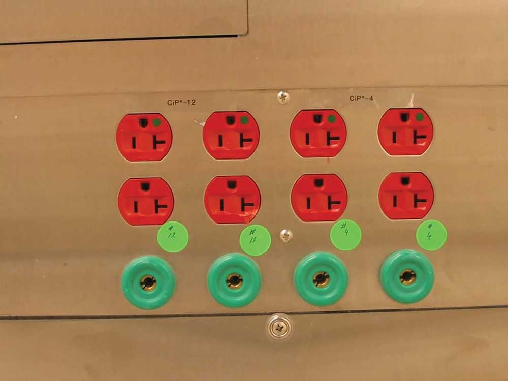
The specialty safety concept in health care facilities is primarily based on ensuring the patient and persons dealing with the patient consist of an equipotential plane surrounding the patient, as mentioned above. To make that equipotential plane a reality, 517.13 provides the assurance of two totally separate equipment grounding systems for each branch circuit supplying receptacles and fixed electrical equipment in patient care areas. There is a reference to this method of two separate equipment grounding systems in NFPA 99 as requiring a redundant grounding for the patient grounding system. However, the word “redundant” is not the appropriate word that should be used, as I will explain later. To accomplish the patient grounding systems in critical care areas in the 1984 NEC and prior editions, patient care areas required grounding and bonding to be established by a busbar with terminals or jacks that served as a collection point for “redundant grounding” of electrical appliances. The name of this collection point was the “patient grounding point” and truly was a redundant grounding system.
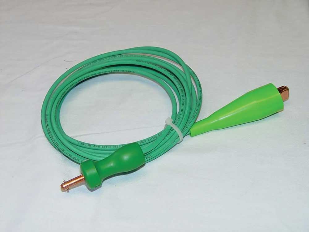
The patient bonding point was designed to accept bonding jumpers (conductors) with a large alligator clamp on one side of the insulated green bonding jumper and a keyed terminal jack designed to insert into the grounding contact on the busbar of the bonding point. These bonding jumpers were used to provide a zero reference from the busbar to each piece of electrical equipment located near the patient. This bonding system worked well when there were few pieces of medical equipment that required bonding but became difficult to use as more and more medical equipment was required in the patient vicinity. Section 517.19(D) in the 2020 NEC still permits this method as an option, especially where trying to overcome and eliminate electromagnetic interference.
Electromagnetic interference can occur where high frequencies are inductively and capacitively coupled from the electrical equipment into a ferrous metal raceway, such as electrical metallic tubing (EMT) or rigid metal conduit (RMC). The ferrous metal raceway acts as a transmission line for this high frequency, which can be reflected back into sensitive electrical equipment causing errors and electronic issues with the equipment. Normally, this electromagnetic interference can be handled with isolated ground receptacles; however, 517.16 does not permit that in patient vicinities. Therefore, the patient equipment grounding point can be a solution to the problem by acting as a shunt for the high frequency to the grounding point.
In the 1987 NEC, a major redesign of the equipment grounding requirements for health care facilities in Article 517 occurred with the advent of new text now found in the 2020 NEC. Section 517.13(A) was revised in 1987 to require that a metal raceway or metal cable assembly be installed that provides a wiring method grounding system that is totally separate from the insulated equipment grounding conductor required by 517.13(B). The term “redundant” was made irrelevant during the 1987 NEC Technical Committee Report and the Technical Committee Comment process, even though NFPA 99 continues to use this antiquated term. To confirm that two totally separate grounding systems were required, a comment from the nonmetallic raceway industry for the 1987 NEC was rejected by the NEC Code Making Panel 17 (CMP-17) [now designated as Code Making Panel 15 (CMP-15)]. The comment requested that a redundant grounding system be permitted.
This comment, submitted by the nonmetallic conduit manufacturers, was to revise 517.13 to permit “redundant” grounding by using two separate insulated equipment grounding conductors. One of these conductors was to be installed unbroken from the origin of the circuit to the last device or piece of electrical equipment. The other conductor was to connect to each receptacle or fixed piece of electrical equipment. This truly would have provided a redundant equipment grounding system without requiring the metal raceway or metal cable assembly. CMP-17 rejected that concept by stating that there was too much of a possibility that an interruption of the grounding system could occur with this method if one of the insulated equipment grounding conductors was to break off. CMP-17 further stated that the intent was to have the metal raceway or metal cable assembly be one complete method of grounding based on 250.118. This would be in addition to the separate insulated equipment grounding conductor, resulting in two totally separate and complete grounding systems to the same receptacle or piece of equipment or both. There have been subtle changes in 517.13 in the past few NECcycles, but the intent since the 1987 NEC is to provide two totally individual and separate equipment grounding systems to receptacles and fixed equipment in a patient care area.
Wiring Methods
There are fourteen different wiring systems in 250.118 that qualify as grounding systems and can be used for 517.13(A) for metal raceway and metal cable assemblies. Still, each must be evaluated as a wiring system to determine if the wiring method can be used as an independent equipment grounding system. I am only going to cover a few of the most common wiring methods used in health care facilities.
Rigid metal conduit (RMC), intermediate metal conduit (IMC), and electrical metallic tubing (EMT) can be used with few, if any, restrictions.
Listed flexible metal conduit (FMC) can be used but, for this wiring method, there are some restrictions. The listed FMC must be terminated in listed fittings (all listed fittings are acceptable for grounding); the circuit conductors in the FMC must be protected by an overcurrent protective device at not greater than 20 amperes; the size of the FMC cannot exceed one and a quarter-inch; and the combined length of FMC, flexible metal tubing (FMT), and liquidtight flexible metal conduit (LFMC) in the same ground-fault current path cannot exceed 1.8 m (6 ft) (that is the combined length of six feet).
Flexible metallic tubing (liquidtight flexible metal without the nonmetallic jacket, as covered in Article 360) can be used with the following restrictions: must have listed fittings; the circuit conductors in the tubing cannot be protected by an overcurrent protective device at over 20 amperes; and the combined length of flexible metal conduit, flexible metal tubing, and liquidtight flexible metal conduit in the same ground-fault current path cannot exceed 1.8 m (6 ft). The reason for the length restriction of 1.8 m (6 ft) for both flexible metal conduit and flexible metallic tubing is the length of six feet will permit enough fault current through the raceway to trip a 20-ampere or smaller overcurrent device in the trip time of 1.5 cycles to 3 cycles of time. Any longer lengths will not permit the device to trip in that time frame and could cause damage or worse.
The last two common wiring methods acceptable for health care facilities that I will cover here are Type AC cable with individual conductors wrapped with paper and MC cable with all the conductors wrapped with clear plastic. A common way to look at this is plastic or paper, just like at the supermarket.
Armored Cable: Type AC
Type AC cable construction is described the product specifications as well as in 320.100 as a cable that has an armor of flexible metal tape and has an internal 16 AWGbonding strip of copper or aluminum in intimate contact with the armor convolutions for its entire length. This bonding jumper short-circuits the convolutions of the metal tape in a ground fault and reduces the amount of inductive impedance that occurs with this wiring method. Type AC cable suitable for use in a health care facility must have both the wiring method as a grounding method plus an additional insulated equipment grounding conductor that is sized at 12 AWG or larger. For easy identification, the Type AC cable, as described in the previous sentence, often has the outside of the metal tape dyed light green making easy identification of this special health care wiring method.
Metal-Clad Cable: Type MC
There are three different types of Type MC cable provided in 250.118, of which there is only one of those acceptable for health care installations and being used commonly. There is smooth tube, corrugated, and interlocked metal tape-type MC cable.
Of the three different types of MC cable, interlocked metal tape type is the most commonly used for health care facility patient care installations, but it is a specialty type of cable. Type MC cable does not normally have the same type of internal 16 AWG bonding jumper that is found in Type AC cable and has all of the internal conductors wrapped in plastic. Refer to the product specifications for Type MC cable for dditional information. The Type MC cable that is acceptable for patient care areas has a 10 AWG aluminum bonding jumper that is located outside the plastic sheath and inside the interlocked metal tape of the MC cable. This bonding jumper acts as a shorting conductor across the inside convolutions of the metallic jacket, similar to the Type AC 16 AWG bonding (shorting) conductor. An additional insulated green 12 AWG or larger equipment grounding conductor must also be provided inside the plastic sheath of the cable assembly.
With both of these cables, the combination of the bonding jumper/metal sheath of the cable and the insulated equipment grounding conductor provides the two separate grounding systems required by 517.13(A) and (B). The bare equipment bonding jumpers for Type AC cable can be terminated by one of three different methods. The first method is to just cut the bonding conductor off as it enters into the connector, the second is to bend it onto the outside of the cable jacket and insert the cable into the connector, and the third method is to wrap it around the convolutions on the outside of the metal jacket and then insert the cable into the connector. Type AC connectors are listed for either of the three methods of installation of health care Type AC cable. With Type AC cable, the insulated equipment grounding must terminate inside the box, based on 250.148, as well as the raceway equipment grounding connection through the raceway fitting. With Type MC cable, the bare 10 AWG aluminum conductor is too large to bend over the outside of the cable assembly and insert into the listed connector, so the bare bonding conductor can be cut off or extended into the box to connect to the other equipment grounding conductors. Since the bare 10 AWG is aluminum, a special purple wire nut, listed for use with both copper and aluminum, would be required.
The last part of establishing an equipotential plane surrounding the patient is to apply 517.13 and also to provide special panelboard bonding in accordance with 517.14. The equipment grounding terminal buses of any panelboards supplying normal and essential branch circuit power to the same patient care area must be connected together with an insulated continuous copper bonding conductor not smaller than 10 AWG. This panelboard bonding conductor is not required to be installed within a raceway since the purpose is to provide bonding from one panelboard to another. In other words, two panelboards serving branch circuits for one patient care bed location must have an insulated 10 AWG copper conductor installed without splice from one equipment ground bus to the other. Where there are more than two panelboards serving one patient bed location, the 10 AWG copper bonding conductor or larger can be broken (terminated) to each grounding bus but not otherwise broken outside the panelboard enclosures. These bonding jumpers between panelboards supplying the single patient bed branch circuits will ensure that there will be minimal or no electrical difference of potential surrounding the patient, even with multiple different sources of power.
Summary
As can be seen by the issues raised in this article, health care installations can certainly be a mystery for even the most well qualified electrical personnel. Care must be taken to ensure that patients and health care personnel do not die from natural causes, such as unknown and undetected spurious electrical currents (electricity and differences of potential are natural). Electrical installers and electrical maintenance personnel must be acutely aware of all aspects of the electrical installations within health care facilities to ensure all circuits are appropriately installed and maintained. Whether the installation is new, a remodel, or normal replacement during maintenance, adherence to the requirements in Article 517 is critical in maintaining safety.