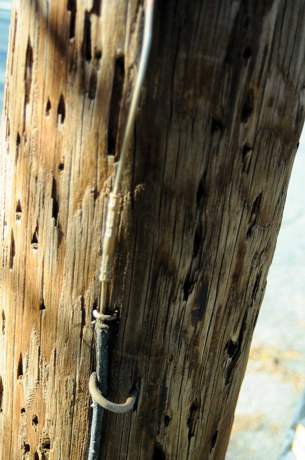
We have continued to see a big problem with stolen ground wires on many utility poles over the years. A utility poles’ grounding conductors [ground wires or “grounds”] contain copper –a highly conductive metal–, but also a highly valued metal in the marketplace. In general, copper wires and rods known as electrical grounds run from the utility pole into the ground. These connections serve a critical safety purpose in the event of a lightning strike or electrical surge, as they direct excess electricity away from the utility wires and grid elements, such as transformers, antennas, public lights, and more; by providing a low resistance path directly into the ground. A ground wire and/or rod helps direct positive electrical charges into earth in a safe, direct and controlled way, where they can be discharged without the risk of electrical shock or fire. People frequently cut and steal electrical pole grounds for the value of the copper they contain.
If these pole grounding conductors connect to transformers, cutting these grounds can be very hazardous. They will pose a risk to not only the thieves but utility workers and local residents in the surrounding community who may come in contact with these utility poles. And if it happens too often to certain locations, it can prove to be a serious shock hazard.
Missing or stolen grounds are a serious safety issue that utilities need to pay closer attention to, but some utilities are not inspecting their facilities regularly and properly to address this issue. This has been especially evident over the past year, as companies have been experiencing many limitations during the COVID-19 pandemic.
There are steps utilities can take to maintain these pole grounds. They should conduct regular inspections to ensure pole grounds have been properly maintained and are not compromised. The best way to inspect utility pole grounds is by physically visiting each pole. While this might be done by vehicle, the pole grounds are not always on the street side of the pole.
Care should be taken in repairing a broken or stolen pole ground. If the ground is connected to a transformer or if other neutral connections are poor, there can be a hazardous voltage on the portion of the pole ground that remains. The best practice is to use some kind of testing device to test for voltage and also use appropriate protective equipment (i.e., rubber gloves rated for the system voltage).
There are a couple of methods by which utilities can make conductors harder to steal. One option is to staple the cables about a foot apart for the first ten feet closest to the ground to make them harder to detach. Once the cable reaches higher than ten feet from the ground, you can then start to space out the staples more. Another option is to disguise the pole grounds as cable TV covers to make them less attractive to thieves. In earlier days, some utilities utilized wooden u-guards over the ground wire. That could still be done today to make them less visible. The material of choice today is typically PVC.
When replacing or restring a missing ground, the length of conductor the same size as the original should be used. A typical distribution pole ground is #6 AWG. Quite often, a compression connector (see photo 1) is used to splice the conductor, although a split bolt is not prohibited. But a split bolt can be easily loosened and the conductor stolen again.
The NESC 2017 edition, Section 9 Code provides practical methods of grounding as one of the means of safeguarding employees and the public from injury that may be caused by electrical potential. According to these guidelines, the neutral, which shall be of sufficient size and ampacity for the duty involved, shall be connected to a made or existing electrode at each transformer location and a sufficient number of additional points with made or existing electrodes to total not less than four grounds in each 1.6 km (1 mi) of the entire line, not including grounds at individual services.
There are a few exceptions to this Code. One exception is where cable or cable in duct is installed underwater, the requirement of made electrodes to total not less than four grounds in every 1.6 km (1 mi) of the entire line does not apply for the underwater portion if the neutral is of sufficient size and ampacity for the duty involved and the requirements of Rule 092B2 are met. However, at all locations where the cable is accessible to personnel, the neutral shall be effectively grounded.
Another exception is for cable or cable in duct installed underground where adherence to a total of not less than four grounds in every 1.6 km (1 mi) would require removing the protective jacket of a buried cable, only to install a ground to meet this rule, the requirement of a total of not less than four grounds in every 1.6 km (1 mi) need not be met. However, at all locations where the cable is accessible to personnel, the neutral shall be effectively grounded.
One additional exception is where the terrain (such as river crossings or mountainous areas) being crossed limits the installation of supporting structures every 0.4 km (0.25 mi) or less, the requirement of made electrodes to total not less than four grounds in every 1.6 km (1 mi) of the entire line does not apply for this portion if the neutral is of sufficient size and ampacity for the duty involved. However, all available structures should be grounded.
It is important to note that this rule may be applied to shield wire(s) grounded at the source and which meet the multi-grounding requirements of this rule. Additionally, multi-grounded systems extending over a substantial distance are more dependent on the multiplicity of grounding electrodes than on the resistance to ground of any individual electrode. Therefore, no specific values are imposed for the resistance of individual electrodes. Finally, the intent is to ensure that grounding electrodes are distributed at approximately 400 m (1/4 mi) or smaller intervals, although some intervals may exceed 400 m (1/4 mi).
If you want to participate in NESC and join the discussion, please contact NESC-Support@ieee.org.