An important part of developing quality overcurrent protection is an understanding of system needs and overcurrent protective device fundamentals. This article discusses these topics with special attention to the application of fuses.
Why Overcurrent Protection?
All electrical systems eventually experience overcurrents. Unless removed in time, even moderate overcurrents quickly overheat system components, damaging insulation, conductors, and equipment. Large overcurrents may melt conductors and vaporize insulation. Very high currents produce magnetic forces that bend and twist bus bars. These high currents can pull cables from their terminals and crack insulators and spacers.
Fires, explosions, poisonous fumes and panic accompany uncontrolled overcurrents all too frequently. This not only damages electrical systems and equipment but may cause injury or death to personnel nearby.
To reduce these hazards, the National Electrical Code® (NEC®), OSHA regulations, and other applicable design and installation standards require overcurrent protection that will disconnect overloaded and faulted equipment.
Industry and governmental organizations have developed performance standards for overcurrent devices and testing procedures that show compliance with the standards and with the NEC. These organizations include: the American National Standards Institute (ANSI), National Electrical Manufacturers Association (NEMA), and the National Fire Protection Association (NFPA), all of which work in conjunction with Nationally Recognized Testing Laboratories (NRTL) such as Underwriters Laboratories (UL).
Electrical systems must meet applicable code requirements including those for overcurrent protection before electrical utilities are allowed to provide electric power to a facility.
What is Quality Overcurrent Protection?
A system with quality overcurrent protection has the following characteristics:
- Meets all legal requirements, such as the NEC, OSHA, local codes.
- Provides maximum safety for personnel, exceeding minimum code requirements as necessary.
- Minimizes overcurrent damage to property, equipment, and electrical systems.
- Provides coordinated protection. Only the protective device immediately on the line side of an overcurrent opens to protect the system and minimize unnecessary downtime.
- Is cost effective while providing reserve interrupting capacity for future growth.
- Consists of equipment and components that are not subject to obsolescence and requires only minimum maintenance that can be performed by general maintenance personnel using readily available tools and equipment.
Overcurrent Types and Effects
An overcurrent is any current that exceeds the ampere rating of conductors, equipment, or devices under conditions of use. The term “overcurrent” includes both overloads and short circuits.
Overloads
An overload is an overcurrent confined to normal current paths in which there is no insulation breakdown.
Sustained overloads are commonly caused by installing excessive equipment such as additional lighting fixtures or too many motors. Sustained overloads are also caused by overloading mechanical equipment and by equipment breakdown such as failed bearings. If not disconnected within established time limits, sustained overloads eventually overheat circuit components causing thermal damage to insulation and other system components.
Overcurrent protective devices must disconnect circuits and equipment experiencing continuous or sustained overloads before overheating occurs. Even moderate insulation overheating can seriously reduce the life of the components and/or equipment involved. For example, motors overloaded by just 15 % may experience less than 50 % of normal insulation life.
Temporary overloads occur frequently. Common causes include temporary equipment overloads (such as a machine tool taking too deep of a cut, or simply the starting of an inductive load such as a motor). Since temporary overloads are by definition harmless, overcurrent protective devices should not open or clear the circuit.
It is important to know that fuses must have sufficient time-delay to allow motors to start and temporary overloads to subside. However, should the overcurrent continue, fuses must then open before the system components are damaged. In general, time-delay fuses hold 500 % of the rated current for a minimum of ten seconds yet will still open quickly on higher values of current.
Short-Circuits
A short-circuit is an overcurrent flowing outside of its normal path. Types of short-circuits are generally divided into three categories: bolted faults, arcing faults, and ground faults.
A short-circuit is caused by an insulation breakdown or faulty connection. During a circuit’s normal operation, the connected load determines the current. When a short-circuit occurs, the current bypasses the normal load and takes a “shorter path,” hence the term ‘short-circuit’. Since there is no load impedance, the only factor limiting the current flow is the total distribution system’s impedance from the utility’s generators to the point of fault.
A typical electrical system might have a normal load impedance of 10 ohms. But in a single-phase situation, the same system might have a load impedance of 0.005 ohms or less. In order to compare the two scenarios, it is best to apply Ohm’s Law (I = E/R for ac systems). A 480 volt single-phase circuit with a 10 ohm load impedance would draw 48 amperes (480/10 = 48). If the same circuit has a 0.005 ohm system impedance when the load is shorted, the available fault current would increase significantly to 96,000 amperes (480/0.005 = 96,000).
As stated, short-circuits are currents that flow outside of their normal path. Regardless of the magnitude of overcurrent, the excessive current must be removed quickly. If not removed promptly, the large currents associated with short-circuits may have three profound effects on an electrical system: heating, magnetic stress, and arcing.
Heating occurs in every part of an electrical system when current passes through the system. When overcurrents are large enough, heating is practically instantaneous. The energy in such overcurrents is measured in ampere-squared seconds (I2t). An overcurrent of 10,000 amperes that lasts for 0.01 seconds has an I2t of 1,000,000 A2s. If the current could be reduced from 10,000 amperes to 1,000 amperes for the same period of time, the corresponding I2t would be reduced to 10,000 A2s, or just one percent of the original value.
If the current in a conductor increases ten times, the I2t will increase 100 times. A current of only 7,500 amperes can melt a #8 AWG copper wire in 0.1 second. Within eight milliseconds (0.008 seconds or one-half cycle), a current of 6,500 amperes can raise the temperature of #12 AWG THHN thermoplastic insulated copper wire from its operating temperature of 75 °C to its maximum short-circuit temperature of 150 °C. Any currents larger than this may immediately vaporize organic insulations. Arcs at the point of fault or from mechanical switching such as automatic transfer switches or circuit breakers may ignite the vapors causing violent explosions and electrical flash.
Magnetic stress (or force) is a function of the peak current squared. Fault currents of 100,000 amperes can exert forces of more than 7,000 lb. per foot of bus bar. Stresses of this magnitude may damage insulation, pull conductors from terminals, and stress equipment terminals sufficiently such that significant damage occurs.
Arcing at the point of fault melts and vaporizes all of the conductors and components involved in the fault. The arcs often burn through raceways and equipment enclosures, showering the area with molten metal that quickly starts fires and/or injures any personnel in the area. Additional short-circuits are often created when vaporized material is deposited on insulators and other surfaces. Sustained arcing-faults vaporize organic insulation, and the vapors may explode or burn.
Whether the effects are heating, magnetic stress, and/or arcing, the potential damage to electrical systems can be significant as a result of short-circuits occurring.
I. SELECTION CONSIDERATIONS
Selection Considerations for Fuses (600 volts and below)
Since overcurrent protection is crucial to reliable electrical system operation and safety, overcurrent device selection and application should be carefully considered. When selecting fuses, the following parameters or considerations need to be evaluated:
- Current Rating
- Voltage Rating
- Interrupting Rating
- Type of Protection and Fuse Characteristics
- Current Limitation
- Physical Size
- Indication
- Current Rating
The current rating of a fuse is the AC or DC current, expressed in amperes, which the fuse is capable of carrying continuously under specified conditions. Fuses selected for a circuit must have ampere ratings that meet NEC requirements, namely those found in NEC Articles 240 and 430. These NEC requirements establish maximum ratings and in some cases, minimum ratings. When selecting a fuse, it is generally recommended to select a current rating as close as possible to the system’s normal running current.
Voltage Rating
The voltage rating of a fuse is the maximum ac or dc voltage at which the fuse is designed to operate. Fuse voltage ratings must equal or exceed the circuit voltage where the fuses will be installed, and fuses used in dc circuits must be specifically rated for dc applications. In terms of voltage, fuses may be rated for ac only, dc only, or both ac and dc. However, exceeding the voltage ratings or using an ac only fuse in a dc circuit could result in violent destruction of the fuse.
The standard 600-volt rated fuses discussed in this section may be applied at any voltage less than or equal to their rating. For example, a 600-volt fuse may be used in a 277 volt or even a 32-volt system, but not any system exceeding 600 volts.
NOTE: This does not apply to semiconductor fuses and medium voltage fuses.
Interrupting Rating
The interrupting rating of a fuse is the highest available symmetrical rms alternating current that the fuse is required to safely interrupt at its rated voltage under standardized test conditions. A fuse must interrupt all overcurrents up to its interrupting rating without experiencing damage. Standard UL fuses are available with interrupting ratings of 10,000 A, 50,000 A, 100,000 A, 200,000 A, and 300,000 A.
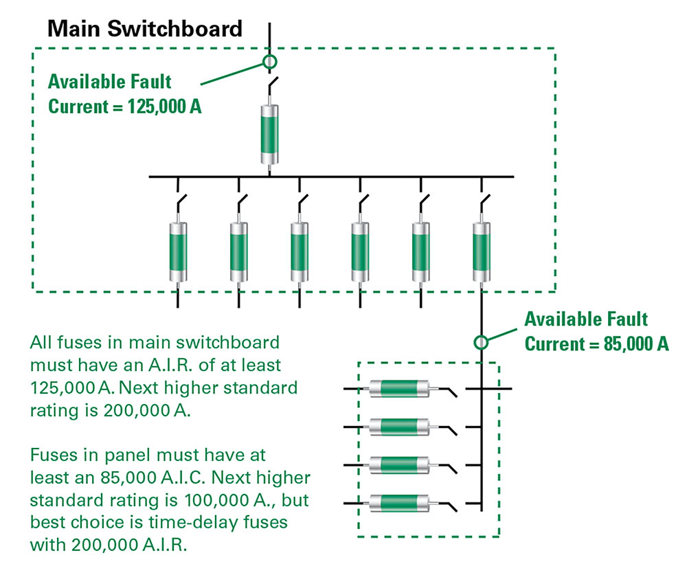
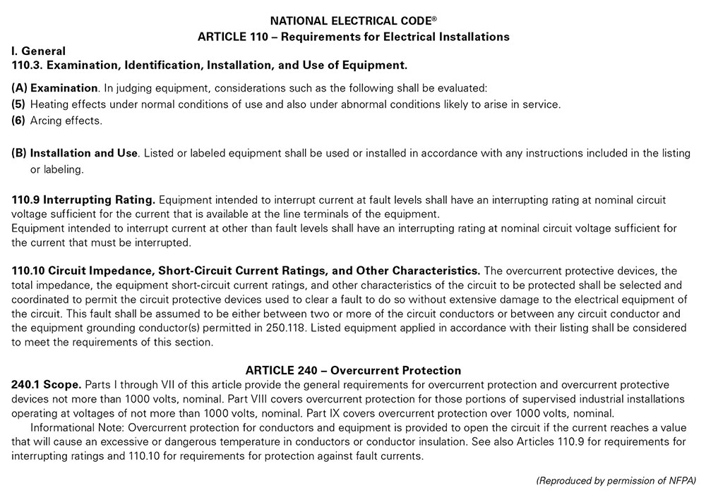
NEC Article 110.9 requires that all equipment intended to break current at fault levels have an interrupting rating sufficient for the system voltage and current available at the equipment’s line terminals. Refer to Figure 1. It is vitally important to select fuses with interrupting ratings which equal or exceed the available fault current.
The recommendation to standardize on fuses with at least a 200,000-ampere interrupting rating (AIR) ensures that all fuses have an adequate interrupting rating while providing reserve interrupting capacity for future increases in available fault current.
II. TYPE OF PROTECTION AND FUSE CHARACTERISTICS
Time current characteristics determine how fast a fuse responds to overcurrents. All fuses have inverse time characteristics; that is, the fuse opening time decreases as the magnitude of overcurrent increases. When properly rated in accordance with NEC requirements, fuses provide both overload and short-circuit protection to system conductors and components. However, in some instances such as when fuses are used to backup circuit breakers or to provide motor branch circuit short-circuit and ground fault protection, fuses provide only short-circuit protection. A fuse’s response to overcurrents is divided into short-circuits and overloads.
Short-Circuits
A fuse’s short-circuit response is its opening time on higher value currents. For power fuses, higher-value currents are generally over 500-600 % of the fuse’s current rating. As stated earlier, all fuses have inverse time characteristics: the higher the current, the faster the opening time. Since short circuits should be removed quickly, inverse time is especially important for short-circuit protection.
Overloads
While fuses must disconnect overloaded conductors and equipment before the conductors and components are seriously overheated, they should not disconnect harmless temporary overloads. To provide sufficient overload protection for system conductors, UL has established maximum fuse opening times at 135 % and 200 % of a fuse’s current rating. All UL Listed fuses for application in accordance with the NEC must meet these limits whether they are fast-acting or time-delay fuses.
As just stated, a fuse is designed to respond to two types of overcurrents – short circuits and overloads. As a result, selecting the proper fuse for a given application usually involves deciding whether to use a time-delay fuse or a fast-acting fuse. A more in-depth review of both possible scenarios is important at this time.
Fast-Acting (Normal-Opening) Fuses
Fast-acting fuses (sometimes called “normal-opening” fuses) have no intentional time-delay. Typical opening times at 500 % of the fuse ampere rating range from 0.05 second to approximately 2 seconds. Fast-acting fuses are suitable for non-inductive loads such as incandescent lighting and general-purpose feeders, or branch circuits with little or no motor load. When protecting motors and other inductive loads, fast-acting fuses must be rated at 200-300 % of load currents to prevent nuisance opening on in-rush currents. Fuses with such increased ratings no longer furnish adequate protection from overloads and only provide short-circuit protection. Overload relays or other overload protection devices must be provided to properly protect conductors and equipment from overload conditions.
All fast-acting fuses provide fast short-circuit response within their interrupting rating. Some are considered current limiting, such as UL Class T and Class J. Others are noncurrent-limiting, such as UL Class H.
Time-Delay (SLO-BLO®) Fuses
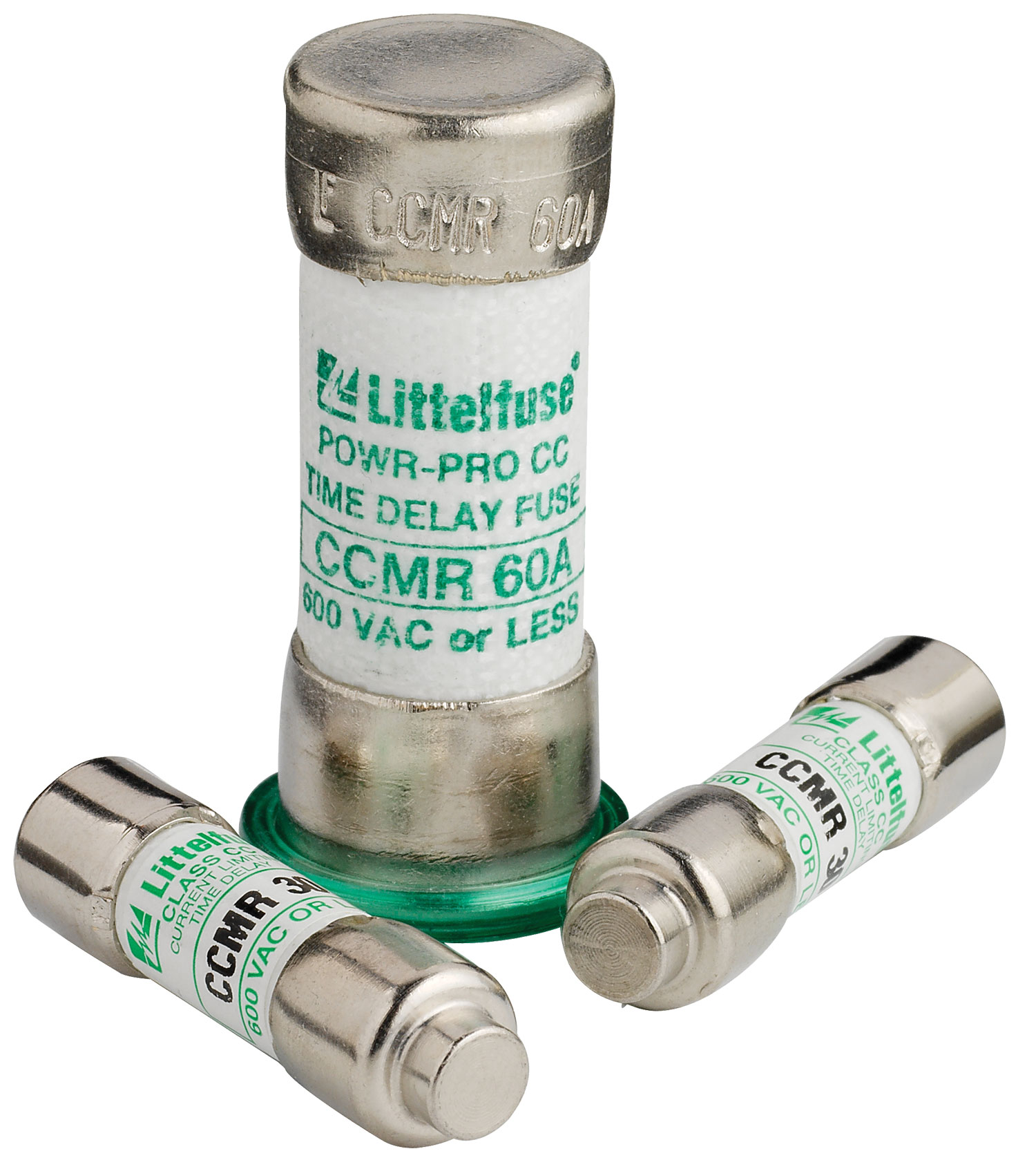
Most UL Class CC, CD, G, J, L, RK5 and RK1 fuses, plus some of the UL Listed miscellaneous fuses are considered time-delay. If so, they are identified as such on the fuse label with the words “Time-Delay”, “T-D”, “D”, or some other suitable marking. Minimum time-delay varies with the fuse class, and to some degree with the fuse ampere rating. UL standards for POWR-GARD® fuse series FLNR, FLNR_ID, FLSR, FLSR_ID, IDSR (UL Class RK5), LLNRK, LLSRK, LLSRK_ID (UL Class RK1), and JTD, JTD_ID (UL Class J) require these fuses to carry 500% rated current for a minimum of 10 seconds. Standards for CCMR and KLDR (UL Class CC and CD) and SLC (UL Class G) fuses require them to carry 200% rated current for a minimum of 12 seconds.
Although there is no UL Classification for time-delay Class L fuses, it is still permissible for them to be marked “Time-Delay.” The amount of time-delay is determined by the manufacturer. In addition to providing time delay for surges and short time overloads, time-delay fuses meet all UL requirements for sustained overload protection. On higher values of current, time-delay fuses are current-limiting; meaning they remove large overcurrents in less than one-half cycle (0.00833 seconds). Time-delay fuses provide the best overall protection for both motor and general purpose circuits, and eliminate nuisance fuse opening and most situations of downtime.
Compared to fast-acting fuses, time-delay fuses can be selected with ratings much closer to a circuit’s operating current. For example, on most motor circuits Class RK5 and RK1 fuses can be rated at 125-150 % of a motor’s full load current (FLA). This provides superior overload and short circuit protection, and often permits the use of smaller, less expensive disconnect switches. Time-delay fuses have gradually replaced most one-time (UL Class K5) and renewable (UL Class H) fuses. Today, more than 50 % of all fuses sold by electrical distributors are time-delay fuses.
Dual Element Fuses
Littelfuse time-delay FLNR, FLNR_ID, FLSR, FLSR_ID, IDSR (UL Class RK5), and LLNRK, LLSRK, LLSRK_ID (UL Class RK1), and some JTD, JTD_ID (UL Class J) series fuses have true dual-element construction meaning the fuse has an internal construction consisting of separate short-circuit and overload sections or elements. Time-delay elements are used for overload protection, and separate fast-acting fuse elements or links are used to provide current-limiting short-circuit protection.
Very Fast-Acting Fuses
This category of fuses exists for limited applications. The principle use of very fast acting fuses is to protect solid-state electronic components, such as semiconductors. Fuse series designated as ‘Semiconductor Fuses’ have special characteristics including quick overload response, very low I2t and Ipeak currents, and peak transient voltages, that provide protection for components that cannot withstand line surges, low value overloads, or short-circuit currents. Very fast-acting fuses are designed for very fast response to overloads and short-circuits and are very current-limiting.
Effect of Ambient Temperature on Fuses
The current carrying capacity of fuses is 110 % of the fuse rating when installed in a standard UL test circuit and tested in open air at 25 °C ambient. This allows for derating to 100 % of rating in an enclosure at 40 °C ambient.
Current Limitation
A current-limiting fuse is one that opens and clears a fault in less than 180 electrical degrees, or in other words, within the first half electrical cycle (0.00833 seconds).
NEC Article 240.2 states that a current-limiting overcurrent protective device must reduce the peak let-through current to a value substantially less than the potential peak current that would have occurred if the fuse were not used in the circuit or were replaced with solid conductors of the same impedance. The total destructive heat energy (I2t) to the circuit and its components is greatly minimized as a result of using current-limiting fuses.
It is important to note that UL Class H ‘Renewable’ fuses designed decades ago are considered non-current limiting. Other than Midget fuses, almost all other fuse types used in today’s electrical systems and applications are considered current-limiting per the above parameters. This selection consideration now involves determining the degree or level of current limitation required to properly protect a given device or system.
It is also important to point out that matching fuse holders and/or fuse blocks must reject non-current-limiting fuses and accept only current-limiting fuses of the stated UL Class.
Physical Size
While often overlooked, the physical size or overall dimensions of the fuse to be used in a given application is another important selection consideration to evaluate. There is a trend toward reduction of size in almost everything, and electrical equipment is no exception. Fuse size is actually determined by the size and dimensions of the fuse block or disconnect switch in which it is installed.
While saving space may be an important factor when selecting the proper fuses, other considerations should not be overlooked. Some of these include:
- Does the smallest fuse have the most desirable characteristics for the application?
- Does the equipment in which the fuse will be installed provide adequate space for maintenance?
- Do smaller fuses coordinate well with the system’s other overcurrent protection?
If looking at just physical dimensions, a 600 volt, 60 ampere, 200,000 AIR, time-delay, dual-element UL Class CD fuse is smaller than a similarly rated UL Class J fuse, which is in turn, considerably smaller than a similarly rated UL Class RK1 or Class RK5 fuse. However, smaller-sized fuses can sometimes have less time-delay or more nuisance openings than their larger counterparts, so it is always important to consider all factors involved.
Indication
Another consideration for selecting the best fuse for a given application is indication. Many of the more commonly used UL fuse classes are now available in both indicating and non-indicating versions. Built-in, blown-fuse indication that quickly identifies which fuse or fuses within an electrical panel or system have blown can be found on the Littelfuse POWR-PRO® LLSRK_ID Class RK1, FLNR_ID, FLSR_ID and IDSR Class RK5, and JTD_ID Class J fuse series. The indicating feature on these fuses provides reduced downtime, increased safety, and reduced housekeeping or troubleshooting headaches and delays. Littelfuse Indicator® fuses will help lower the costs associated with downtime, provide longer fuse life by minimizing nuisance openings, increase system performance by minimizing equipment damage, and improve safety by minimizing accidents.
III. GENERAL FUSING RECOMMENDATIONS
Based on the above selection considerations, the following is recommended:
Fuses with ampere ratings from 1/10 through 600 amperes
- When available fault currents are less than 100,000 amperes and when equipment does not require the more current-limiting characteristics of UL Class RK1 fuses, FLNR and FLSR_ID Series Class RK5 current-limiting fuses provide superior time-delay and cycling characteristics at a lower cost than RK1 fuses. If available fault currents exceed 100,000 amperes, equipment may need the additional current-limitation capabilities of the LLNRK, LLSRK and LLSRK_ID series Class RK1 fuses.
- Fast-acting JLLN and JLLS series Class T fuses possess space-saving features that make them especially suitable for protection of molded case circuit breakers, meter banks, and similar limited-space applications.
- Time-delay JTD_ID and JTD series Class J fuses are used in OEM motor control center applications as well as other MRO motor and transformer applications requiring space saving IEC Type 2 protection.
- Class CC and Class CD series fuses are used in control circuits and control panels where space is at a premium.
Fuses with ampere ratings from 601 through 6,000 amperes
For superior protection of most general-purpose and motor circuits, it is recommended to use a product like the POWR-PRO® KLPC series Class L fuses. The Class L fuses are the only time delay fuse series available in these higher ampere ratings.
SELECTION CONSIDERATIONS FOR FUSE HOLDERS
Equally important to the selection of the proper fuse is the correct selection of the proper fuse holder or fuse block for a given application. Fuse holders are available using most of the same selection considerations outlined above for UL fuse classes. Considerations for fuse holders include:
- Current Rating
- Voltage Rating
- Interrupting Rating
- Physical Size
- Indication
Additional selection considerations for fuse holders and fuse blocks include:
- Number of poles
- Mounting configuration
- Connector type
Number of Poles
The number of poles for each set of fuses is determined by the characteristics of the circuit. Most fuse block series are available in 1-, 2-, or 3-pole configurations, although some are also available with four or more poles. The option to gang individual fuse blocks into longer strips will be determined by the available space and type of wire being used.
Mounting Configuration
Depending on the fuse block design, another selection consideration to evaluate is how the fuse block is mounted or inserted into the panel. Historically, fuse blocks simply screwed into the back of the panel, but many newer designs have now added (or replaced the screw-in design with) a DIN rail mounting capability. The DIN rail mounting feature allows the blocks to be quickly installed and removed from the rails.
Connector Type
For Littelfuse fuse blocks, a choice of three connector types or wire terminations is available:
- Screw – for use with spade lugs or ring terminals.
- Screw with Pressure Plate – for use with solid or stranded wire without terminal and recommended for applications where vibration will be a factor.
- Box Lug – the most durable of the three options and used with all types of solid wire and Class B and Class C stranded wire.
There are a few additional aspects to keep in mind when selecting the fuse holder or fuse block for a given application. UL Class H blocks accept Class H, Class K5, and Class R fuses. Similarly, Midget-style fuse blocks accept both Midget and UL Class CC fuses.
Both UL Class R and Class CC fuse holders contain a rejection feature which prevents the insertion of a different class or type of fuse. The physical size and dimensions of UL Class J and Class T fuses accomplish the same thing in preventing the insertion of a different class of fuse as well.
V. CIRCUIT PROTECTION CHECKLIST
To select the proper overcurrent protective device for an electrical system, circuit and system designers should ask themselves the following questions, before a system is designed:
- What is the normal or average current expected?
- What is the maximum continuous (three hours or more) current expected?
- What inrush or temporary surge currents can be expected?
- Are the overcurrent protective devices able to distinguish between expected inrush and surge currents, and open under sustained overloads and fault conditions?
- What kind of environmental extremes are possible? Dust, humidity, temperature extremes and other factors need to be considered.
- What is the maximum available fault current the protective device may have to interrupt?
- Is the overcurrent protective device rated for the system voltage?
- Will the overcurrent protective device provide the safest and most reliable protection for the specific equipment?
- Under short-circuit conditions, will the overcurrent protective device minimize the possibility of a fire or explosion?
- Does the overcurrent protective device meet all the applicable safety standards and installation requirements?
Answers to these questions and other criteria will help to determine the type overcurrent protection device to use for optimum safety, reliability and performance.
The performance capabilities of various fuses are graphically represented by two different types of fuse characteristic curves: time-current curves and peak let-through charts. These curves and charts define the operating characteristics of a given fuse, and assist system designers and engineers in selecting the proper fuse to protect equipment and electrical systems.
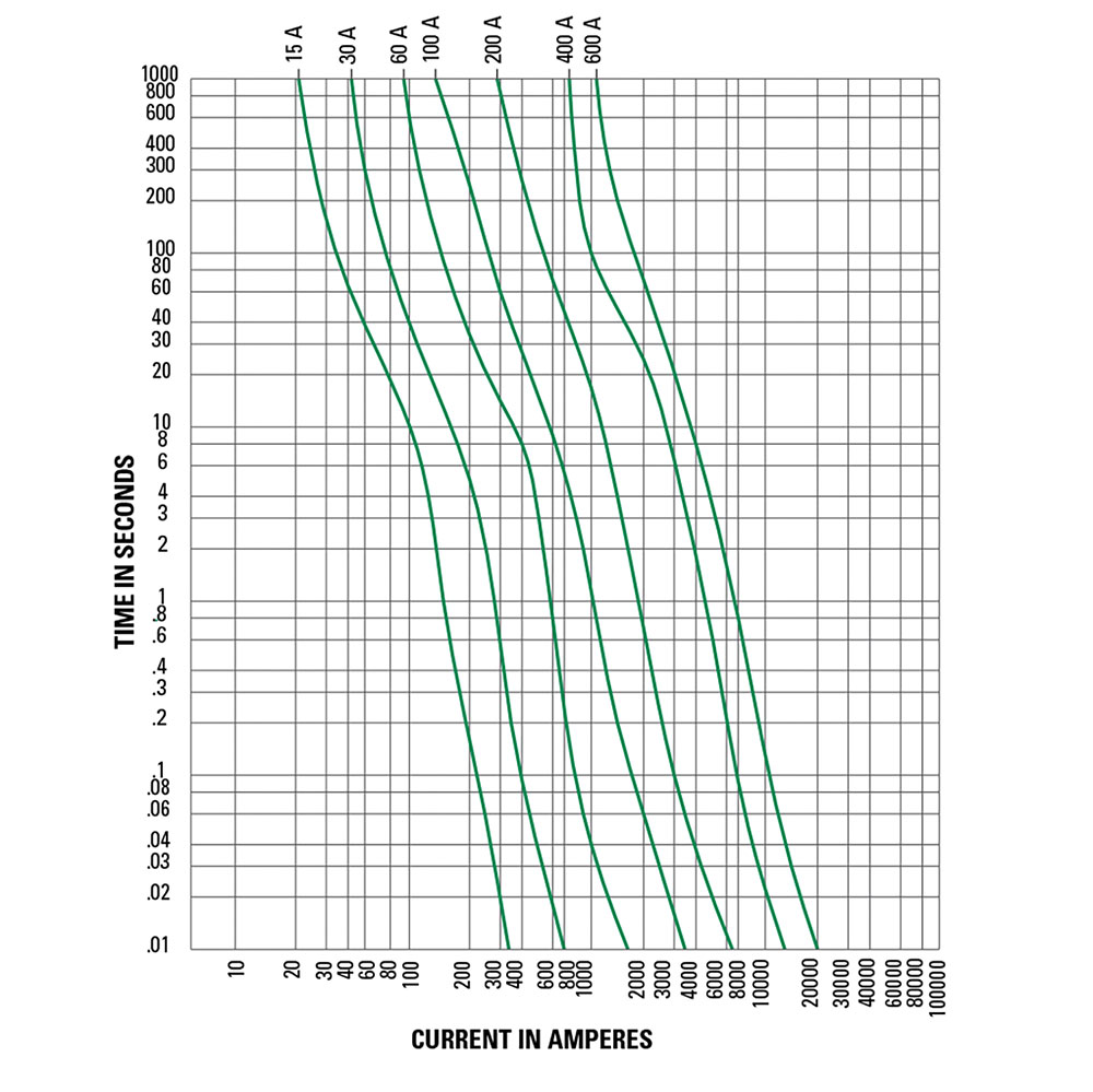
Understanding Time-current Curves
Time-current curves provide a graphical representation or plot of a fuse’s average melting (opening) time at any current. In order to make the curves more readable, the performance information is presented on log-log paper. The overcurrent values appear across the bottom and increase in magnitude from left to right. Average melting times appear on the left-hand side of the curve and increase in magnitude from bottom to top. The ampere ratings of the individual fuses for a given series are listed at the top and increase in rating from left to right. Figure 2 shows the average melting time curves for a typical time-delay fuse series.
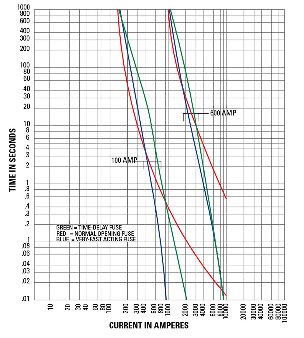
As discussed earlier in the Fuseology Fundamentals section, time-delay, fast-acting, and very fast-acting fuses all respond differently based on the overcurrents occurring in the systems each is protecting. To illustrate the basic differences between each type of fuse, figure 2 compares the average melting times for 100 and 600 amp ratings of three fuse types: Littelfuse dual-element, time-delay LLSRK series class RK1 fuses (green); Littelfuse normal opening NLS series class K5 fuses (red); and Littelfuse very fast acting L60S series semiconductor fuses (blue). To better illustrate this point, Table 1 also compares the opening times for each of these fuses.

Peak Let-through Charts
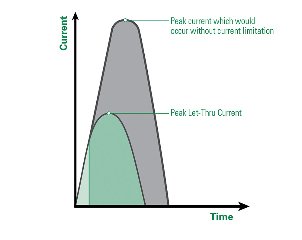
Peak let-through charts illustrate the maximum instantaneous current through the fuse during the total clearing time. This represents the current limiting ability of a fuse. Fuses that are current-limiting open severe short-circuits within the first half-cycle (180 electrical degrees or 0.00833 seconds) after the fault occurs. Current-limiting fuses also reduce the peak current of the available fault current to a value less than would occur without the fuse. This reduction is shown in Figure 3.
A fuse’s current-limiting effects are shown graphically on Peak Let-through charts such as the one shown in Figure 4. The values across the chart’s bottom represent the available (also referred to as potential or prospective) rms symmetrical fault current. The values on the chart’s left side represent the instantaneous available peak current and the peak let through current for various fuse ratings.
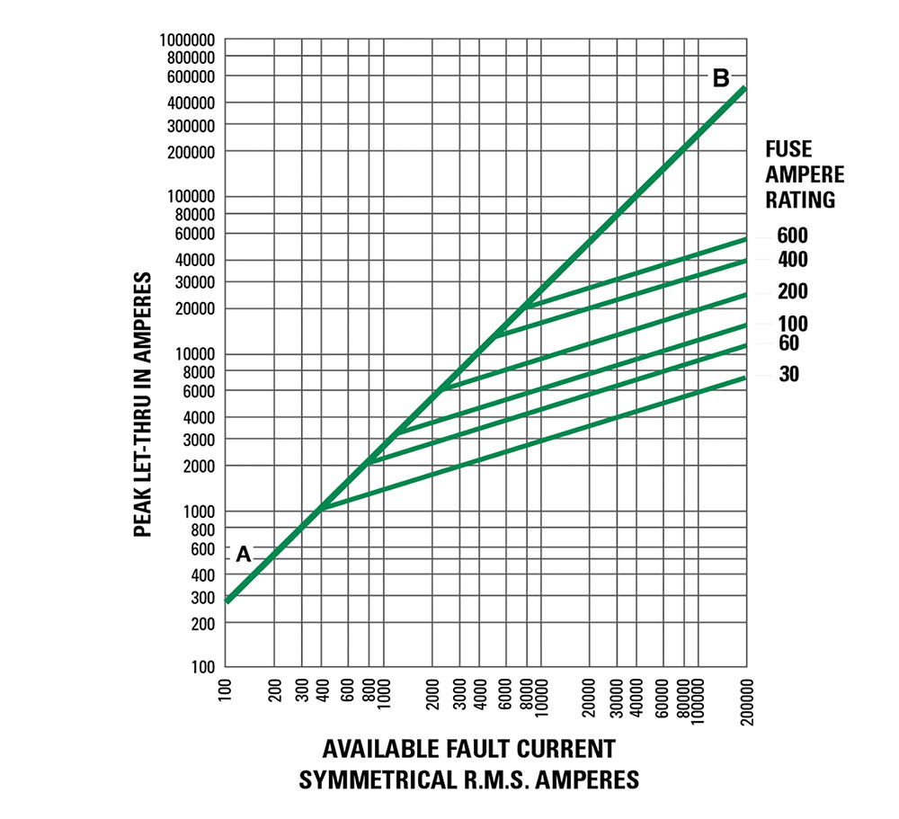
To better explain the function of these charts, let’s run through an example. Start by entering the chart on the bottom at 100,000 rms symmetrical amperes and read upwards to the A-B line. From this point, read horizontally to the left and read the instantaneous peak let-thru current of 230,000 amperes. In a circuit with a typical 15% short-circuit power factor, the instantaneous peak of the available current is approximately 2.3 times the rms symmetrical value. This occurs since the A-B line on the chart has a 2.3:1 slope.
The diagonal curves that branch off the A-B line illustrate the current-limiting effects of different fuse ampere ratings for a given fuse series. To continue the example from above, enter the chart in Figure 4 on the bottom at 100,000 rms symmetrical amperes and read upwards to the intersection of the 200 ampere fuse curve. Now read from this point horizontally to the left and read a peak let-through current of approximately 20,000 amperes.
What this tells us is that the 200 ampere fuse has reduced the peak current during the fault from 230,000 amperes to 20,000 amperes. In other words, this is the current-limiting effect of the 200 ampere fuse. 20,000 amperes is less than one-tenth of the available current. This is important because the magnetic force created by current flow is a function of the peak current squared. If the peak let-through current of a current-limiting fuse is one-tenth of the available peak, the magnetic force is reduced to less than 1/100 of what would occur without the fuse.
Using the Peak Let-through Charts (“Up-Over-and-Down”)
Peak Let-through charts for Littelfuse POWR-GARD® fuses can be found online at littelfuse.com/technicalcenter. These charts are useful in determining whether a given fuse can properly protect a specific piece of equipment.
For example, given an available fault-current of 100,000 rms symmetrical amperes, determine whether 600 amp 250 volt time-delay Class RK1 fuses can sufficiently protect equipment that has a 22,000 amp short-circuit rating. Refer to Figure 5.
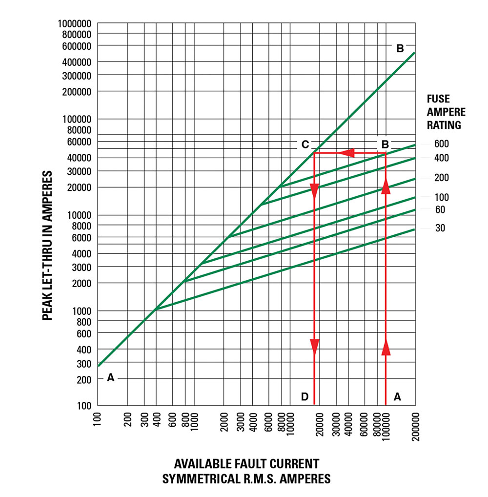
Start by locating the 100,000 A available fault-current on the bottom of the chart (Point A) and follow this value upwards to the intersection with the 600-amp fuse curve (Point B). Next, follow this point horizontally to the left to intersect with the A-B line (Point C). Finally, read down to the bottom of the chart (Point D) to read a value of approximately 18,000 amps.
Can the fuse selected properly protect the equipment for this application? Yes, the POWR-PRO® LLNRK 600 ampere RK1 current-limiting fuses have reduced the 100,000 amperes available current to an apparent or equivalent 18,000 amps. When protected by 600-amp LLNRK RK1 fuses, equipment with short-circuit ratings of 22,000 amps may be safely connected to a system having 100,000 available rms symmetrical amperes.
This method, sometimes referred to as the “Up-Over-and-Down” method, may be used to:
- Provide back-up short-circuit protection to large air power circuit breakers.
- Enable non-interrupting equipment such as bus duct to be installed in systems with available short-circuit currents greater than their short circuit (withstand) ratings.
However, this method may not be used to select fuses for backup protection of molded case or intermediate frame circuit breakers. NEC Article 240.86 requires Series Ratings. Refer to the NEC for more information.
UL Listed fuse-to-circuit breaker series ratings are now available from most national load center and panelboard manufacturers. Listings are shown in their product digests, catalogs, and online. Many local builders have also obtained fuse-to-circuit breaker series ratings.
Short-Circuit Current Rating (SCCR)
Since 2005, the NEC has required industrial control panels to be labeled with their SCCR. These labels allow users and inspectors to compare the SCCR of the equipment to the available fault current in order to avoid potential hazards in facilities.
Selective Coordination
A “coordinated” or “selective” system is a system whose overcurrent protective devices have been carefully chosen and their time-current characteristics coordinated.
Only the overcurrent device immediately on the line side of an overcurrent will open for any overload or short-circuit condition.
Since the advent of electrical and electronic equipment, businesses have become entirely dependent on the continuous availability of electric energy. Loss of power halts all production and order processing, yet expenses continue to increase. Even many UPS systems become unintentionally non-selective causing power loss to computers and other critical equipment. Non-selectivity may defeat otherwise well-engineered UPS systems.
In a selective system, none of this occurs. Overloads and faults are disconnected by the overcurrent protective device immediately on the line side of the problem. The amount of equipment removed from service is minimized, the faulted or overloaded circuit is easier to locate, and a minimum amount of time is required to restore full service.
For these and many other reasons, selectivity is the standard by which many systems are judged and designed.
Fuse Selectivity
To get a better sense of how to ensure that fuses are selectively coordinated within an electrical system, refer to Figure 6. This figure shows typical average melting time current curves for one class of fuses. Note that the curves are roughly parallel to each other and that for a given overcurrent, the smaller fuse ratings respond quicker than the larger ratings. The heat energy required to open a fuse is separated into melting I2t and arcing I2t. The sum of these is the total clearing I2t.
For a system to be considered coordinated, the smaller fuse total clearing I2t must be less than the larger fuse melting I2t. In other words, if the downstream (branch) fuse opens the circuit before the overcurrent affects the upstream (feeder) fuse element, the system will be considered selective. This can be determined by analyzing curves displaying melting and total clearing I2t, or from minimum melting and maximum clearing time-current curves.
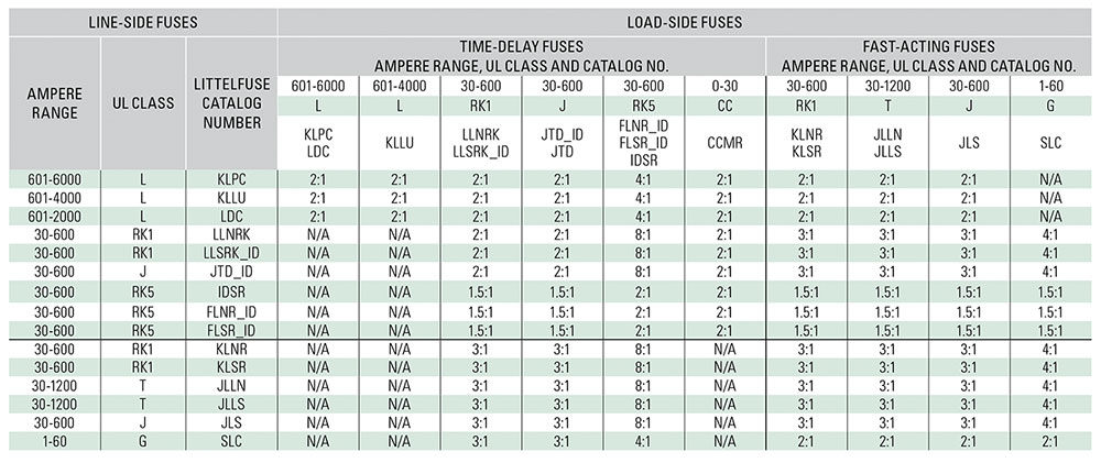
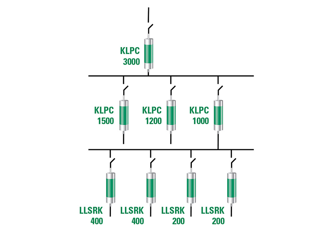
But the simplest method of coordinating low voltage power fuses is by using a Fuse Coordination Table such as the one shown in Table 2. This table is only applicable for the Littelfuse POWR-PRO® and POWR-GARD® fuse series listed. Tables such as this greatly reduce design time. For example, the coordination table shows that POWR-PRO KLPC Class L fuses coordinate at a two-to-one ratio with other Class L fuses, with POWR-PRO LLNRK / LLSRK / LLSRK_ID series Class RK1 fuses, and POWR-PRO JTD / JTD_ID series Class J fuses.
In the system shown in figure 7, the 3000-amp Class L main fuses are at least twice the ratings of the 1500, 1200, and 1000-amp Class L feeder fuses. Using the 2:1 ratio just referenced above, it is determined that these fuses will coordinate. The Coordination Table also shows that the LLSRK_ID series time-delay RK1 feeder and branch circuit fuses coordinate at a two-to-one ratio with the Class L feeder fuses, so the entire system in Figure 7 would be considered 100% coordinated.
Circuit Breaker Coordination
As a result of the numerous types of circuit breakers and circuit breaker trip units available in today’s market, developing a coordinated circuit breaker system or coordinating circuit breakers with fuses is beyond the scope of this article.
NEC Requirements for Selective Coordination
Component Short-Circuit Protecting Ability
As shown in figure 8, the NEC requires equipment protection to be coordinated with overcurrent protective devices and the available fault current in order to prevent extensive damage to the equipment. Essentially, this means that electrical equipment must be capable of withstanding heavy overcurrents without damage or be properly protected by overcurrent protective devices that will limit damage.
When a severe fault occurs in an unprotected circuit, current immediately increases to a very high value. This is the available or prospective fault current. Some fuses respond so quickly to the increasing current that they interrupt current within the first half-cycle – or before the current even reaches its first peak. This is illustrated in figure 3. Such fuses are termed “current-limiting fuses.”
Current-limiting fuses stop damaging current faster than any other protective device, and greatly reduce or totally prevent component damage from high fault currents. This performance capability helps users meet NEC Article 110.10 requirements.
For more information, visit Littelfuse.com/TechnicalCenter
Disclaimer Notice – Information furnished is believed to be accurate and reliable. However, users should independently evaluate the suitability of and test each product selected for their own applications. Littelfuse products are not designed for, and may not be used in, all applications. Read complete Disclaimer Notice at www.littelfuse.com/product-disclaimer.
© 2021 Littelfuse, Inc.