Although Section 10 of the Canadian Electrical Code, Part I (CE Code), which applies to grounding and bonding, has been re-written in the 2018 edition of the Code, I keep receiving questions from the readers regarding the fundamentals of grounding and bonding.
In this article, I’ll share with the readers eight questions (which is usually enough) on this subject and will provide the answers based on the requirements of Section 10 of the CE Code.
Question #1. What is an “electrical system.”
Answer to question # 1. An electrical system is a complete electrical installation in which the electric energy is provided by a single energy source to the utilization equipment via a distribution network. A typical example of such a source for an electrical system could be a secondary winding of a transformer, a generator, a battery, a photovoltaic module, a fuel cell, a hydrokinetic turbine generator, etc. For example, an electrical installation supplied from a transformer or bank of transformers can be considered an electrical system; installation supplied from a different transformer, or a generator would be considered a different electrical system.
When a 347/600 V electrical system supplies a 600 V:120/208 V transformer, then primary winding (usually “delta” connected) of this transformer represents a load, similarly to a heating or motor load, but the secondary (120/208 V “Wye” connected) winding represents a source of a new 120/208 V electrical system.
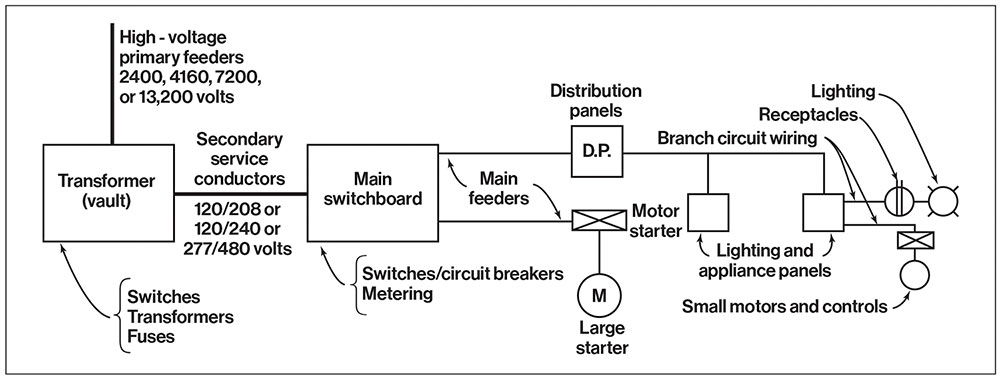
A typical single-line diagram of a building electrical distribution system is shown in figure 1.
Question #2. When is an electrical system required to be solidly grounded?
Answer to question #2. Subrule 10-206(1) of the CE Code states the following:
“10-206(1) AC systems exceeding extra-low voltage shall be solidly grounded if
-
- a) by doing so, their maximum voltage-to-ground does not exceed 150 V; or
- b) the system incorporates a neutral conductor.”
It means that if an electrical system has a voltage to ground not more than 150 V (i.e., a typical 120/240 V, single-phase, 3-wire system, or a typical 120/208 V 3 phase, 4-wire system), then the safety objective for solid grounding connection of such electrical system and objective for bonding of metal non-current carrying parts of electrical equipment supplied by such system, is to protect the users by establishing a low impedance path between the grounded conductor and the non-current carrying conductive parts of the system – to stabilize system voltage and to facilitate the operation of protective devices.
It also means that if an electrical system incorporates a neutral conductor, such a system also must be solidly grounded.
Question #3: What is the system bonding jumper?
Answer to question # 3: System bonding jumper — a conductor that interconnects the system grounded point with the non-current carrying metal enclosure of the source and interconnects the neutral conductor coming from the source to the service equipment with the non-current carrying metal enclosure of the service equipment.
Clause 6.9 of the CSA safety standard C22.2 No. 0.19 “Requirements for service entrance equipment” clarifies that the neutral conductor coming from the source of a solidly grounded system to the service equipment would have to be terminated in the neutral assembly, provided with a sufficient number of connectors, and that one of such connectors, must be used for connection of the system bonding jumper to the enclosure of service equipment [see item (d) in Clause 6.9]:
“6.9
Equipment intended to function as service equipment for solidly grounded systems involving a neutral or other grounded service conductor shall be provided with a neutral assembly located within the service-disconnecting compartment. The neutral assembly shall be provided with an adequate number of suitable pressure-terminal connectors, clamps, or other approved means for connecting the following:
(a) the incoming (grounded) neutral conductor;
(b) the corresponding outgoing (neutral) conductor, if any required;
(c) the grounding conductor;
(d) the bonding conductor to the enclosure;
(e) the bonding conductor to the metal service raceway.”
Question #4. Is a grounding conductor allowed to be connected to the metal non-current carrying enclosure of the service equipment?
Answer to question #4. In a solidly grounded system, a grounding conductor must be connected only to a grounded service conductor (to a neutral conductor brought to the service equipment from the solidly grounded power supply source). Item 6.9(c) in standard C22.2 No. 019 (see text immediately above) clearly articulates this fact.
Rule 10-210(a) of the CE Code, Part I also provides this requirement as follows:
“10-210 Grounding connections for solidly grounded ac systems supplied by the supply authority (see Appendix B)
The grounded conductor of a solidly grounded ac system supplied by the supply authority shall
be connected to a grounding conductor at one point only at the consumer’s service…. “
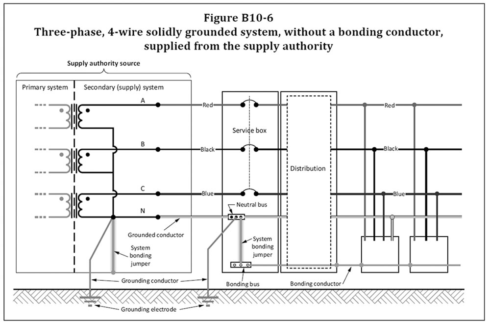
Only a system bonding jumper must be connected to the enclosure of service equipment when a solidly grounded system is provided by the supply authority. (see Figure B10-6 of the CE Code, Part I):
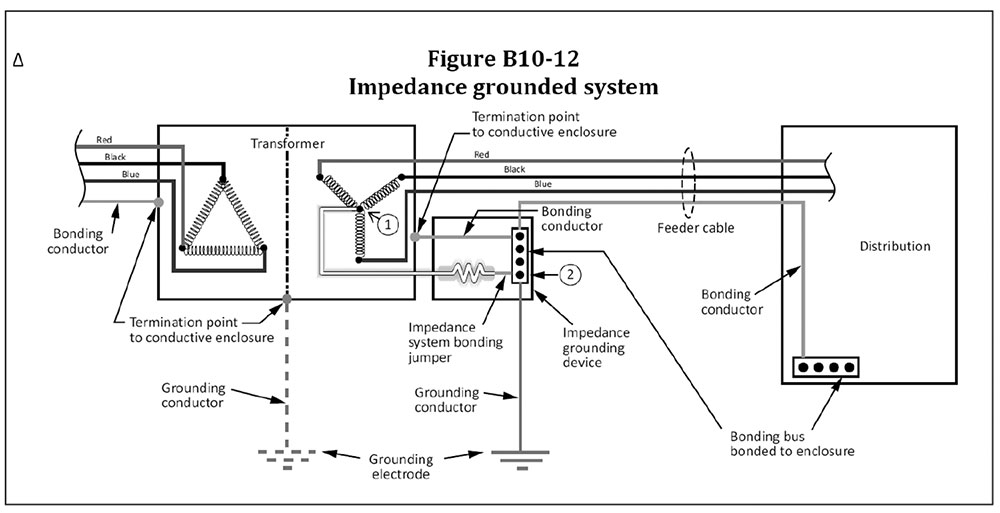
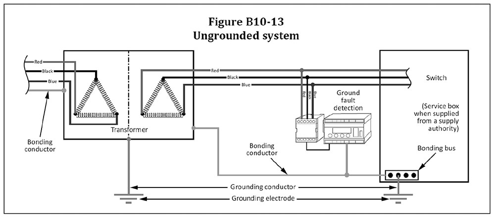
If, however, an impedance grounded system or ungrounded system is provided, then a grounding conductor is permitted to be connected to the metal, non-current carrying enclosure of the service equipment (see Figures B10-12 and B10-13 of the CE Code, Part I).
Question #5: What does a single point grounding mean?
Answer to question # 5: It means that the connection of a solidly grounded system to a grounding electrode via a grounding conductor must be made at a single point only so, that there is no objectionable passage of current over the grounding conductors. Ideally, such single-point grounding should be at the source of every newly derived solidly grounded system. However, when such solidly grounded system is provided by the power supply authority/electric utility (it should be noted that installations by utilities are outside the scope of the CE Code), such single-point grounding of the solidly grounded system must be established (in addition to the grounding of this system by the power supply authority/utility), at the service equipment/service box, see Figure B10-6 and Rule 10-210 of the CE Code:
“10-210 Grounding connections for solidly grounded ac systems supplied by the supply authority (see Appendix B)
The grounded conductor of a solidly grounded ac system supplied by the supply authority shall
-
- a) be connected to a grounding conductor at one point only at the consumer’s service;
- b) have a minimum size as specified
- i) for a bonding conductor; and
- ii) for a neutral conductor when the grounded conductor also serves as a neutral;
- c) be connected to the equipment bonding terminal by a system bonding jumper; and
- d) have no other connection to the non-current-carrying conductive parts of electrical equipment on
the supply side or the load side of the grounding connection.“
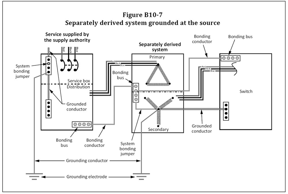
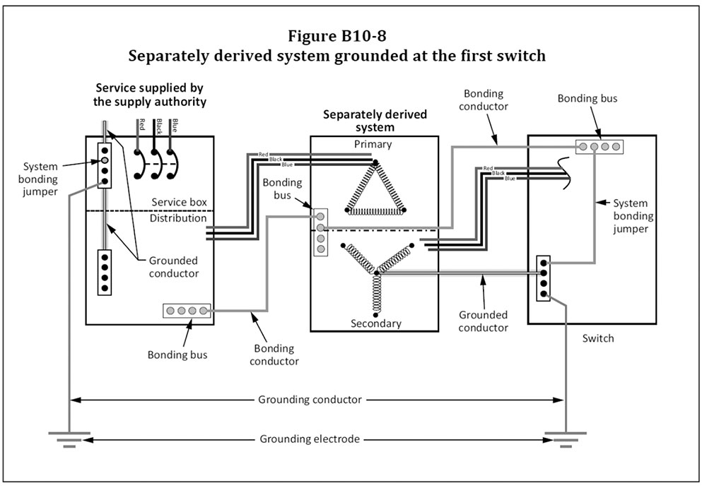
If in addition to the solidly grounded system supplying a building, another (separately derived) solidly grounded system is created in the building (i.e., if, for example, the 347/600 V solidly grounded system supplies the building, and a new separately derived 120/208 V solidly grounded system is created on the secondary “Y” connected winding of a stepdown transformer), this new, separately derived solidly grounded system must have a single point of grounding at the source of this system, or at the first switch controlling the system. (see Figures B10-7 and B10-8 of the CE Code):
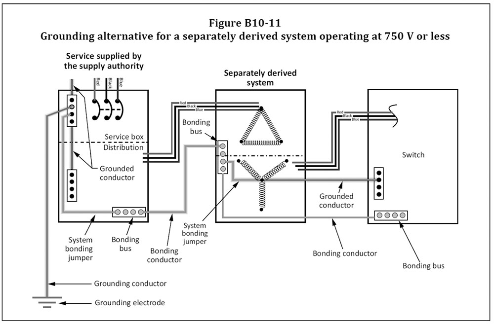
However, Subrule 10-212(2) allows an exception from this requirement. See Subrule 10-212(2) and Figure B10-11:
“10-212 Grounding connections for solidly grounded separately derived ac systems (see Appendix B)
1) Except as permitted by Subrule 2), the grounded conductor of a solidly grounded separately derived ac system shall
-
- a) be connected to the equipment bonding terminal by a system bonding jumper
- i) at the source;
- ii) at the first switch controlling the system; or
iii) at the tie point, where two or more systems terminate at a tie point;
-
- b) be connected to a grounding conductor at the same point on the separately derived system where the system bonding jumper is connected; and
- c) have no other connection to the non-current-carrying conductive parts of electrical equipment
on the supply side or the load side of the grounding connection.
2) A separately derived ac system operating at 750 V or less shall be permitted to be grounded by the system bonding jumper that is connected to the bonding conductor included in the primary supply.“
If a separately derived solidly grounded system is provided not in addition to the main solidly grounded system supplying the building, but as an alternative to this main system (i.e., provided by a generator), and a neutral is not interrupted by the automatic transfer switch, then the neutral of the solidly grounded system derived by the generator may be connected to the grounding electrode via a grounding conductor established at the service of the main solidly grounded system (see diagram in figure 8):
Question #6: How is a system bonding jumper sized?
Answer to question # 6: The size of the system bonding jumper (and the bonding conductor) installed at the service equipment must be based on the ampacity of ungrounded service conductors.
Subrule 10-616(2) clarifies this subject as follows:
“10-616(2) The size of a bonding conductor installed in accordance with Rule 10-604 at service equipment shall not be less than that determined in accordance with Table 16 based on the allowable ampacity of the largest ungrounded conductor.“
Question #7: How to size a grounding conductor?
Answer to question # 7: Subrule 10-114(1) of the CE Code provides the following requirement on this subject:
“10-114 Grounding conductor size (see Appendix B)
1) Except as permitted by Subrule 2), the grounding conductor shall be sized not smaller than
-
- a) No. 6 AWG if of copper; or
- b) No. 4 AWG if of aluminum.”

Question #8: Why is the size of a grounding conductor smaller than the size of a system bonding jumper?
Answer to question # 8: The system bonding jumper is a part of the bonding system which consists of non-current carrying metal enclosures of electrical equipment, interconnected by bonding conductors which will carry fault current back to the source of the solidly grounded system via a system bonding jumper at the service equipment and the grounded service conductor.
The primary function of the grounding conductor is to establish a common reference to ground and to create an equipotential plane by connecting the grounded service conductor with earth.
The size of a grounding conductor for a solidly grounded system does not have to be larger than No. 6 AWG copper or No. 4 AWG aluminum, as the grounding conductor carries only a very small portion of the fault current back to the source via a parallel fault path, and this small portion of the fault current depends on the total impedance of the grounding circuit, including the earth resistance. As the ampacity of the grounded service conductor (neutral) is sufficient to carry the fault current for the entire duration of a fault, the size of the grounding conductor is almost irrelevant for the purpose of its role in mitigating faults.
Of course, in high voltage installations, where a station ground electrode is required in accordance with Section 36 of the CE Code, sizing of station ground electrode conductors and sizing of conductors connecting all non-current carrying metal equipment and structures to the station ground electrode would have to comply with Rules 36-302 and 36-308 of the CE Code, Part I, as Section 36 supplements or amends general provisions of Section 10.
Hopefully, answers to the posted eight questions clarify this interesting and important subject. However, as usual, the authority having jurisdiction for the administration of the CE Code should be consulted in respect to each installation.