Ground faults arise when current flows from an energized conductor to ground inadvertently. The return path of the fault current is through living beings or equipment touching the grounding system. Ground fault detection is critical to protecting people and animals from shock or death.
It doesn’t take much ground-fault current to cause harm. Extensive research in the 1960s determined the amount of current and voltage needed to cause ventricular fibrillation (where a heart stops beating) in humans. These studies found that as little as 70 mA through the heart was enough to cause fibrillation. The refinement of transistor technology provided a means of sensing currents as low as 0.003 A (3 mA) to energize a relay that would decouple the power supply.
OSHA documents spell out the general relationship between the amount of current received and the reaction when current flows from the hand to the foot for just one second.
- At 1 mA, you feel a slight tingle.
- At 5 mA, you feel a slight shock, not painful but disturbing. The average individual can let go, but involuntary reactions can lead to injuries.
- At 6–25 mA, there is painful shock, and muscular control is lost.
- The 9–30 mA level is called the freezing current or “let-go” range. At this level, many humans cannot get their muscles to work, and they can’t open their hand to let go of a live conductor.
- At 50–150 mA, there will be extreme pain, respiratory arrest, and severe muscular contractions. The individual cannot let go, and death is possible.
- At 1,000–4,300 mA, there is ventricular fibrillation. Muscular contraction and nerve damage occur. Death is most likely.
- At 10,000+ mA, there will be cardiac arrest with severe burns and probable death.
Besides endangering lives, ground faults can also lead to costly fires and other equipment damage. Numerous safety regulations and electrical codes exist to prevent and protect against ground faults.
Ground fault regulations
The size of conductors, set points, and subsequent actions are all considerations for selecting a ground fault sensor. What do the local codes require for protection and disconnect? What is the main goal in setting up a ground fault device? Is it focused on personnel protection or electrical device/process protection?
In North America, ground fault circuit interrupters (GFCI) have been required by the National Electric Code (NEC) since the late 1960s. As the technology became more reliable, the NEC mandated GFCIs in many more applications to reduce the number of deaths from electrical shock.
GFCI receptacles and circuit breakers were a huge step forward from prior designs using core balance transformers connected to current sensitive relays. The compact form factor, one-piece design, and simple installation of receptacles and circuit breakers resulted in a significant reduction in fatalities leading to a greater interest in ground fault protection. The NEC sets requirements for where a GFCI will be installed. The system design engineer follows the NEC requirements based on Underwriters Laboratories standard UL 943, Ground-Fault Circuit-Interrupters. The UL specification designates what fault current level will cause the circuit to be de-energized, how quickly it must disconnect, and several other points, including a self-test function. The minimum amount of latency between when the fault occurs and when the circuit is de-energized is based on a mathematical formula so that more time can elapse when the fault is low than when the fault is more severe:
The Time in seconds (T) = (20 /FI) [fault current in mA to the power of 1.43].
T= (20/6)1.43= 5.593 for a fault of 6 mA.
The circuit must be disconnected in 5.59 seconds to meet this requirement. If the fault is more significant at 30 mA, the circuit must be de-energized in 0.56 seconds, 560 ms. If the fault is 250 ms or higher, the monitored circuit must be disconnected in 25 ms.
The NEC refers to personnel protection as ground fault circuit interrupters tested to UL 943A requirements, while in Canada, the standard is CSA (Canadian Standards Association) C22.2 and in Mexico NMX-J-520 from UL.
Industrial ground fault sensors should be marked as recognized under UL 1053 (Standard for Ground-Fault Sensing and Relaying Equipment), UL 508 (Standard for Industrial Control Equipment), or one of the other categories of UL 943: Class B, C, or D.
- UL 1053 is specific for ground fault sensing and relaying equipment with no stated current levels or time to operate.
- UL 508 is an even broader category that covers a variety of automation components.
When using a ground fault sensor to control a shunt-trip breaker, both components (sensing device and circuit breaker) must be tested together to verify the circuit is interrupted quickly enough to be considered a GFCI that meets UL 943 requirements, and that the two parts, sensing and disconnecting method, meet the other specific UL requirements for this standard.
Protecting processes
While personnel safety is a major concern of ground fault protection, industrial settings dictate additional considerations. Manufacturing facilities normally employ a variety of safety protections for employees working with electrical machinery. Personal Safety Devices (PSD) used properly help minimize exposure to electrical dangers and allow fault current trip levels to be safely raised, minimizing nuisance trips and preventing undesired process interruptions. Ground fault detection can also be used to initiate controlled stops, alert other upstream processes, and even be used as part of a predictive maintenance program to repair or renovate equipment before a complete breakdown can occur.
The requirements of UL 943 for personnel protection (avoiding shock to humans) are well established and under constant refinement, while standards for equipment protection are less stringent. The primary aim of equipment protection is to keep a fault from damaging machinery. Circuits supplying heating loads (heat strips, heat trace, and snow melting equipment) are usually not disconnected until the fault current exceeds 30 mA or more. Electric vehicle charging stations are now required to have GFCI personnel protection according to 625.22, under a separate UL Standard, UL 2231-1 (Standard for Safety for Personnel Protection Systems for Electric Vehicle (EV) Supply Circuits: General Requirements).
The 2017 NEC says the following:
Ground-fault protection of equipment shall be provided for fixed outdoor electric deicing and snow-melting equipment. [Section 426.28]
Section 427.22 also requires that:
Ground-fault protection of equipment shall be provided for electric heat tracing and heating panels. This requirement shall not apply in industrial establishments where there is alarm indication of ground faults, and the following conditions apply:
1) Conditions of maintenance and supervision ensure that only qualified persons service the installed systems, and
2) continued circuit operation is necessary for the safe operation of equipment or processes. [Section 427.22]
The 2020 NEC states:
Ground-fault protection of Equipment: Ground-Fault protection of equipment shall be provided for fixed outdoor electric deicing and snow-melting equipment. [Section 426.28]
2017 NEC states:
The overcurrent protective devices that supply the marina, boatyards, and commercial and noncommercial docking facilities shall have ground-fault protection not exceeding 30 mA. [Section 555.3]
For the 2020 NEC, the ground-fault protection (GFP) requirements of marinas, boatyards, and docking facilities was extensively revised. These GFP requirements (previously located at 555.3) were divided into three parts to provide clarify for these important ground-fault requirements. Section 555.35(A)(1) addresses shore power receptacles with individual GFPE not to exceed 30 milliamperes (mA). Section 555.35(A)(2) addresses 15- and 20-ampere receptacles for other than shore power with Class A GFCI protection (4 to 6 mA) being provided in accordance with 210.8 through a reference at 555.33(B)(1). Section 555.35(A)(3) addresses feeder and branch-circuit conductors providing power to individual slips or piers and installed on docking facilities to be provided with GFPE set to open at currents not exceeding 100 mA with coordination with downstream GFPE permitted at the feeder overcurrent protective device.
The 2017 NEC calls for ground-fault protection for high-current supplies, too. Sections 215.10 and 230.95 deal with currents of 1,000 A or more and voltages of 480 or higher. Section 517.17 also stipulates where fault detection is required in hospitals and other health care facilities.
The importance of protecting an electrical system against faults-to-earth cannot be overstated. This type of fault sensing is not over-current detection, so fusing or circuit breakers will keep the conductors and insulation from being damaged.
Detection methods
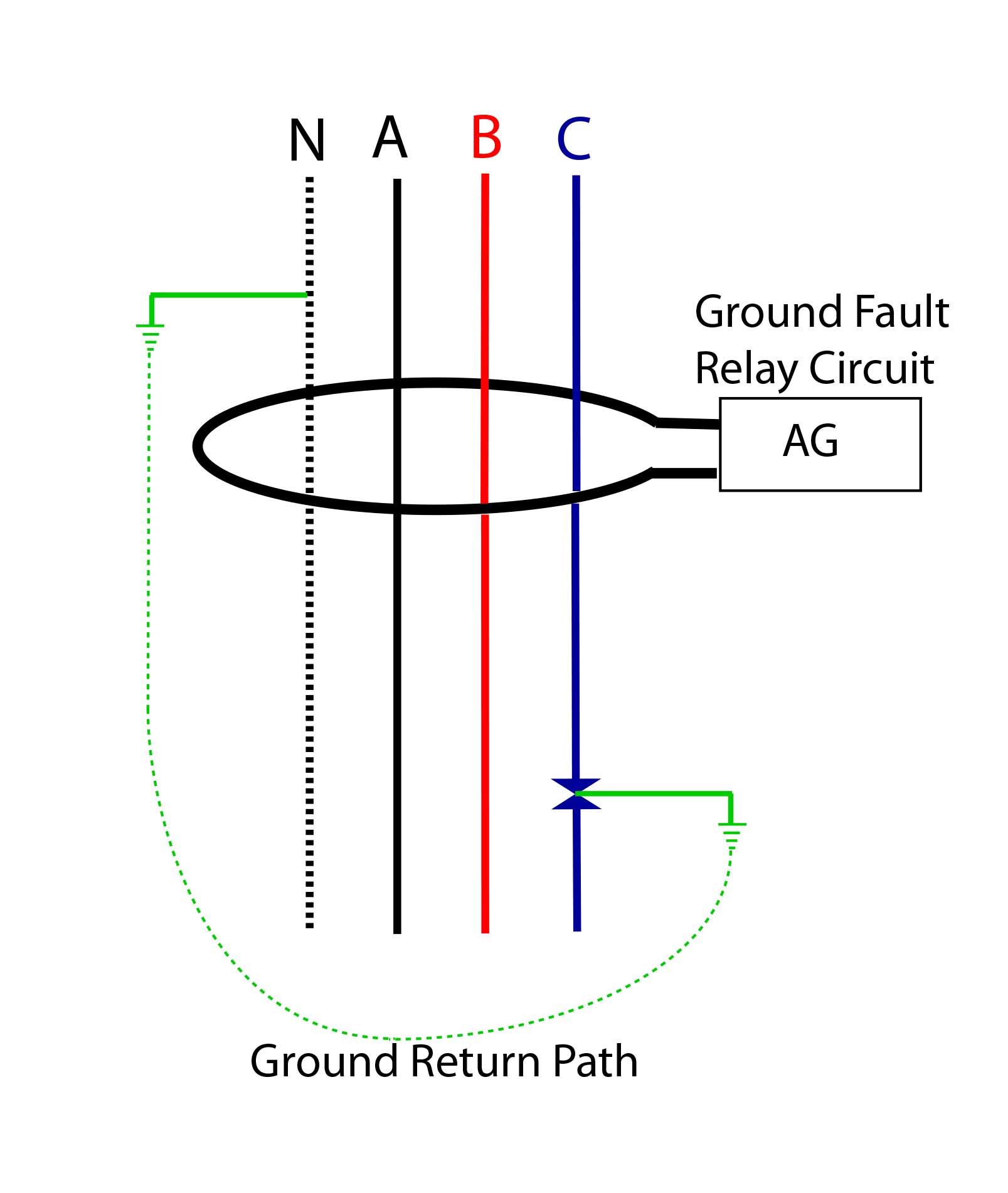
The primary method of fault detection utilizes a single ring of magnetically permeable metal wound with many turns of small gauge wire (forming a current transformer or toroid) surrounding all the current-carrying conductors. If there is more current supplied to the load than is returned to the source, this sensing toroid produces a low voltage in the windings. This voltage is amplified and used to trigger an action such as energizing a solenoid to open a set of contacts (see figure 1).
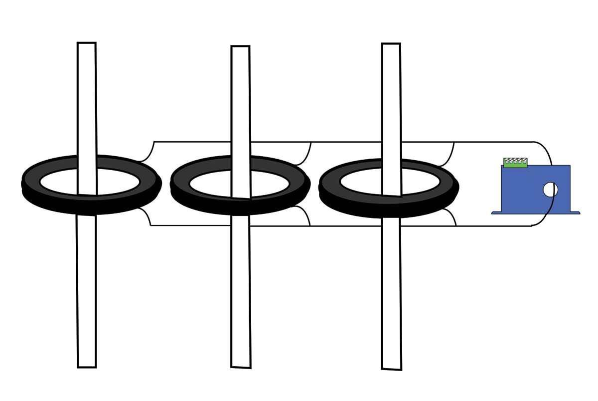
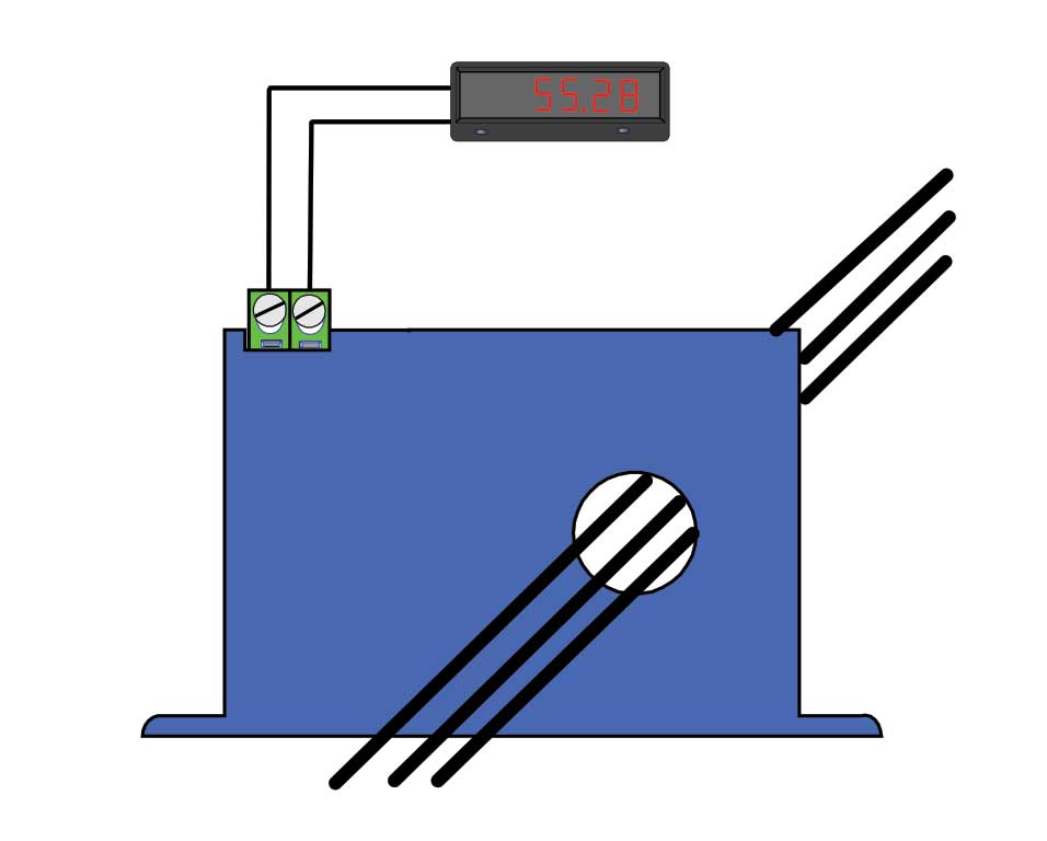
It is also possible to place a current transformer over each conductor and to connect the secondaries to a sensing device installed to monitor the resulting current unbalance (see figure 2). Each current transformer must be rated to handle the maximum current in each conductor. The accuracy of this multiple current transformer method is inherently less precise than using a single toroid due to manufacturing and material tolerances.
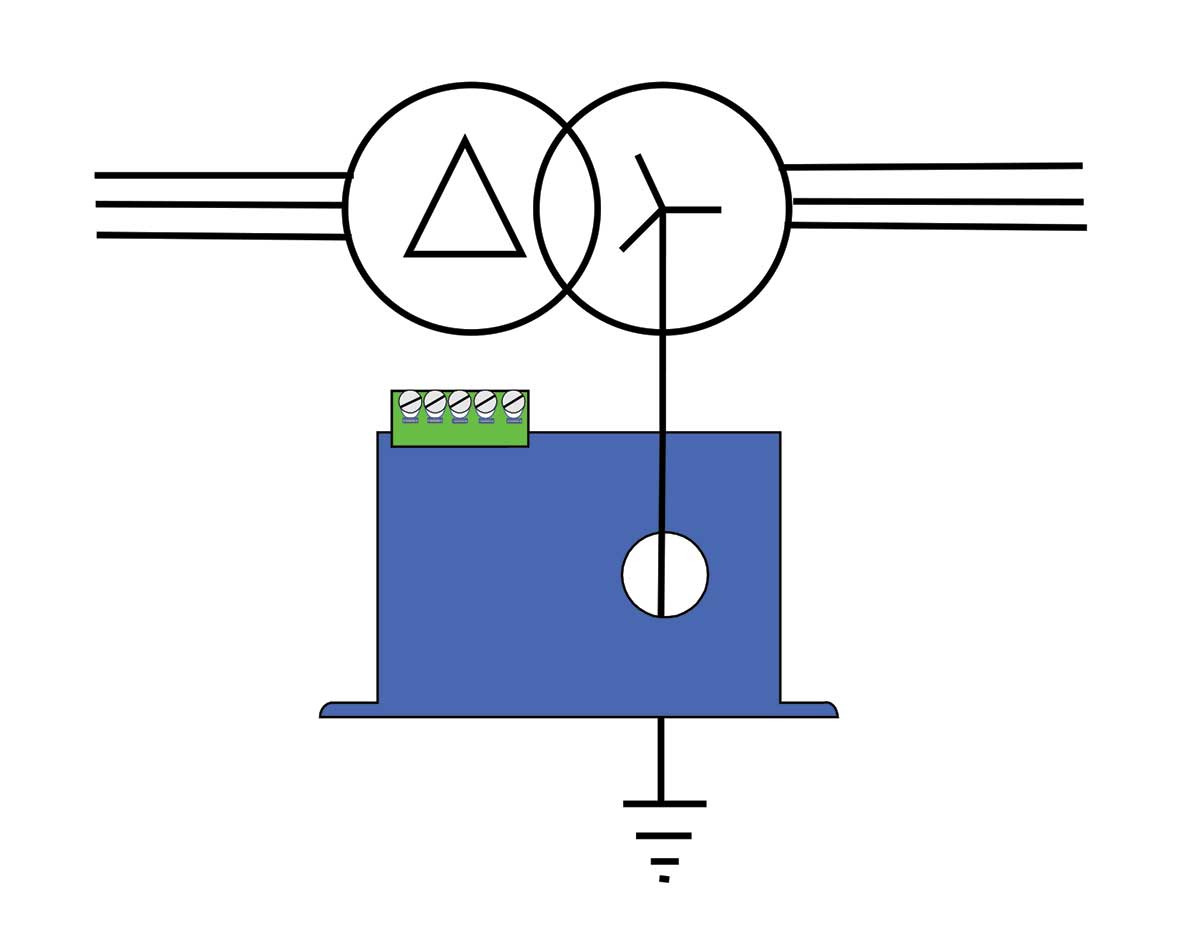
A similar approach can be used to monitor the entire load of a machine or distribution panel supplied by a wye-connected (star) transformer and bonded to earth at the machine location (see figure 3). Passing only the bonding conductor through a ground fault sensor will perform the same function as using a large toroid over all the conductors.
In most industrial equipment protection applications, the ground-fault sensor output performs one of two operations: A contact closes a circuit to energize the operating solenoid of a shunt trip circuit breaker, or a contact opens a circuit powering a contactor or motor starter operating coil. How the sensor output interacts with the rest of the control system is completely at the discretion of the system designer.
Circuit breakers come in a variety of styles. Some can accept feature-enhancing accessories (such as for under-voltage trip, alarm contacts, and interchangeable trip plugs). The most common is the shunt-trip breaker that allows the circuit to be opened from a remote location (acting as if there was an over-current condition). This action is commonly accomplished by a magnetically operated solenoid that pushes or pulls a latching mechanism to open the breaker contacts. In some applications, the shunt-trip device turns off a load in an emergency.
For example, most auto fuel dispensing stations have an emergency switch that disconnects all fuel pumps if there is a problem. This switch closes the circuit to operate a shunt-trip breaker, removing power from the pumps. The circuit breaker must be reset manually once the fault condition has been addressed and mitigated.
When a shunt-trip is used with an auto-reset ground fault sensor, the sensor contact closes the circuit to the shunt solenoid when it detects a fault over the sensor trip point. As in other cases, the breaker must be reset manually after the cause of the fault is determined and mitigated. Because power to the monitored load is turned off, and the only way to restore power is to reset the circuit breaker. Using a shunt-trip accessory effectively transforms an automatically resetting sensor into a latching device.
Even if the cause of the fault is removed from the load and the sensor remains powered from an isolated source (recommended for all installations), the load cannot be energized until the breaker is reset. A latching output sensor, like the auto-reset models, is typically equipped with an integral test button. Two additional terminals allow attachment of an external contact — usually a button mounted to the enclosure door — enabling the sensor to be reset after a fault is detected without opening the panel.
Another common method used with a ground fault sensor is to have the contact open the circuit providing power to a contactor coil, de-energizing the load – typically multiple heating elements or a motor-driven pump or fan. Opening a contact in a control system sounds easy, but in most ground-fault sensing applications, that contact must be closed before the monitored load is energized to allow the contactor coil to do its job.
Manufacturers offer both normally energized and normally de-energized versions of auto-reset ground-fault sensors. The more common of the two is normally de-energized in which the output, whether solid-state or an electromechanical relay, does not change state unless there is a fault-to-ground exceeding the trip point.
The normally energized version is sometimes referred to as fail-safe. Here, the output changes state when the sensor first powers up. The output returns to normal or “shelf-state” condition when one of two things happens: the sensed fault current exceeds the trip point or the power to the sensor is removed.
In the case where a normally open, normally energized solid-state output model opens the circuit powering a contactor coil, the output contact would be open at shelf state and closed when the monitored circuit is not passing current to ground, and the sensor is energized. The sensor output will open, turning off the monitored load if the sensor power is interrupted or if the load passes current to ground exceeding the trip point. It is important to understand that the monitored circuit might not energize if the sensor did not see power first, as energizing the sensor closes the output contact. More commonly, the sensor selection would be normally closed, normally de-energized (solid-state) with the contact opening only when current exceeding the trip point passes to ground.
With electromechanical relay outputs, the operation is the same. In normally energized versions, the output relay is energized with sensor power applied, so the contacts change state when the sensor has power. The relay will then return to shelf state when there is a loss of power to the sensor, or the fault current exceeds the trip point.
When an auto-reset sensor output controls a contactor, it’s best to use a three-wire connection method (like a standard momentary motor-start/stop-button setup utilizing a mechanical interlock on the contactor), so the contactor must be re-engaged after the sensor trips. Alternatively, a latching-output version of the sensor is an option.
In some code jurisdictions, a contactor might not be considered a circuit disconnect. The local inspector, specifier, or AHJ (authority having jurisdiction) has the final say based on the locally adopted Code.
Many system designers tend to specify sensors that will monitor several loads simultaneously by installing the sensor before a final distribution point. The problem is that any minor leakage in each load accumulates, resulting in a higher leakage current level overall.
As an example, visualize a machine that produces silicon wafers for electronics. Several heating elements warm chemical wash processes, several motors perform product positioning, and there are transformers adjusting voltage levels for various process controls. Sensors can be set to trip at relatively low levels if the motors, transformer loads, and heating elements are monitored for faults individually. But if a single sensor protects all loads, the trip point likely must be set much higher, reducing the protection level of each piece of equipment.
Heating elements seldom leak low-level current the way motors and transformers do. In most cases when heaters fail, there is a direct short-to-ground, or the circuit is completely open. Heat trace cable runs do tend to leak small amounts of current to earth, or there may be capacitance losses in long runs.
With loads such as motors and transformers, small imperfections in the varnish insulation of the windings can let low levels of current pass to earth. While humans can seldom feel 3 or 4 mA currents, this low current leakage can rise over time until it becomes a concern both to personnel and the equipment itself.
The ability to precisely monitor ground-fault leakage lets the operator decide how to handle any ground-fault conditions. In applications where deterioration over time is expected, the monitoring of ground leakage levels can determine specific maintenance or replacement needs and prevent costly unexpected equipment failure and shutdowns. There are numerous applications where leakage-to-ground can exceed 30 mA yet not cause harm. And in some circumstances, disconnecting power prematurely may cause significant machine or process damage. Environmental conditions, such as excessively humid or wet conditions caused by washdown or failing enclosure seals, may elevate leakage.
In applications where actions are required at predetermined or specified leakage levels, the factory calibrated setpoint will simplify setup. Once the setpoint is established, the designer chooses how to specifically handle the fault. Local codes may determine the sequence of events once a fault occurs.
Environments characterized by widely ranging temperature and moisture conditions wreak havoc on electrical systems. Changes in heat and humidity eventually break down protective insulation to cause ground leakage. Wet environments pose additional concerns as potential shock hazards multiply.
Unlike moisture sensors that must be wired back to the motor control center, the ground fault sensor installs directly in the control panel, minimizing wiring. Industrial electrical heaters are prone to ground leakage from the breakdown or contamination of insulation. The on/off output of the ground-fault sensor can be used to trigger a circuit interruption device (such as a shunt-trip breaker) or a monitoring device (like a PLC) to determine the required action.
Special Situations
It can be useful to review how ground-fault equipment has served in particular applications that have unique needs. For example, recent updates to NEC Article 555 require that marina owners consider ground-fault protection at both the individual slips and at the power distribution center feeding the separate branches to each slip’s power pedestal. Typical power feeds now require sensors that can handle conductors carrying more than 300 A, necessitating the use of additional components.
To address this problem, manufactures such as NK Technologies have developed a sensor with an aperture measuring four inches in diameter, allowing conductors (carrying 800 A or more) to pass through the sensor easily (see figure 4).
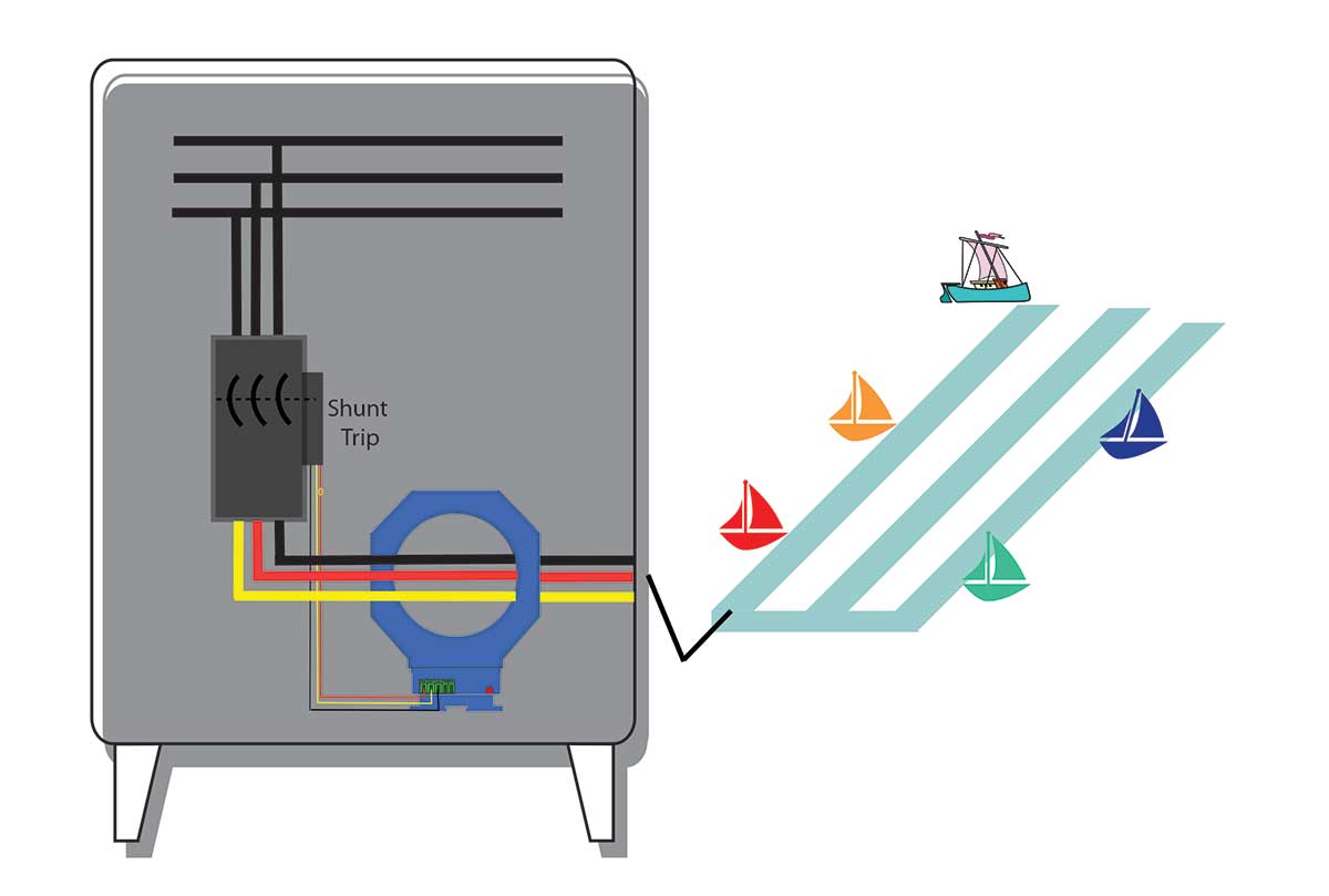
These large-aperture AG-LC sensors can monitor the main circuit feeding the pedestals and energize a shunt trip breaker protecting the entire docking facility. Smaller aperture sensors can monitor individual power pedestals at each slip, with the sensor output energizing a shunt-trip breaker at the pedestal.
In the case of kitchens, NEC 2017 Section 210.8(B)(2) requires GFCI for personnel protection in commercial kitchen equipment with “single-phase receptacles rated 150 V to ground or less, 50 A or less, and three-phase receptacles rated 150 V to ground or less, 100 A or less.” Prior to this change, only 15- and 20- A single-phase circuits of 125 V or less needed this level of protection. Circuit breakers and receptacles meeting this requirement are readily available and quite common. Requirements above 20 A or needing three-phase protection are a more difficult issue.
Additionally, commercial kitchen steamers and grills sometimes retain humidity while stored prior to installation, so units must be “burned in” or energized for at least two hours before normal use. The additional moisture present during this process increases the ground-fault leakage to a point above the 5-mA trip level. To avoid nuisance tripping during the burn-in cycle, a ground-fault sensor must allow a temporary rise in the setpoint.
To handle such situations, some sensors offer adjustable capabilities as a standard feature. A factory placed range jumper is installed at the highest setpoint (30 mA), allowing the equipment to operate during the initial burn-in. With the burn-in complete, the sensors can be readjusted to the 5-mA setpoint (see figure 5).

The fabrication of silicon wafers into semiconductor chips involves hazardous chemicals and extreme heat. The SEMI standard S22-071b provides guidelines regarding the safety of semiconductor processing equipment, including Emergency Mains Off (EMO) circuitry design. This standard requires a means for the operator to easily disconnect mains power should any problem arise during processing.
Because there are electrical heating elements throughout the fabrication equipment, ground fault protection is paramount. The elements are monitored in each process segment, and fault detectors are set at fairly low trip points. If there is a fault-to-earth through the heating element, sensors selectively shut down only the affected part of the process. If several heating processes short simultaneously, a sensor with a bit of delay and higher trip point shuts off the main power feed. Here, sensors with adjustable setpoints and delays help manage the controlled shut down of the system in case of critical failures (see figure 6).
It is relatively easy and quite common to detect low-level current in ac circuits. In North America, codes require all electrical outlets mounted in wet conditions to be protected with ground-fault circuit interrupters. If AC current of 4 to 6 mA passes to ground, a circuit breaker or the contacts in the power receptacle open before there’s an electrocution. Most electrical heating elements must also be protected to keep equipment from damage in the event of a fault.
In contrast, trying to detect the same fault condition in a dc circuit with a floating ground is not as simple. With the proliferation of photovoltaic panels and other alternative power sources, the need for ground-fault detection in dc-powered systems is critical.
Solar panels or battery-operated systems use positive and negative conductors that are insulated. When connections get wet, this insulation becomes compromised, and current can pass to earth. Water is the most common cause of dc fault current, while deteriorating insulation and contaminants on battery housings are additional factors. Because DC current leakage to earth presents a dangerous situation, early fault detection is essential. Fault detection that doesn’t add impedance to the monitored circuit is the safest approach.
References
- NFPA 70®: National Electrical Code®, 2017 edition. Copyright © 2016, National Fire Protection Association. For a full copy of NFPA 70, please go to www.nfpa.org.
- NK Technologies, www.nktechnologies.com