Neon signs and field-installed skeleton tubing installations require a transformer or power supply to step up the voltage to a high level that will cause ignition of connected neon tubing. This transformer can be considered the “heart beat” of the neon sign or outline lighting system. Recent articles in the IAEI News have been written to provide information relative to neon signs and neon installations. This article will visit some of the general requirements one must be aware of to properly install or inspect a neon transformer or power supply. Keep in mind that installation conditions can vary from site to site. There are some important factors and concerns involved with this type of installation that require close attention. High voltages require increased focus on insulation, spacing, and types of wiring methods and products used. Specified minimum clearances for high voltage conductors must be maintained.
Listing and Marking Requirements
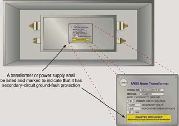
Figure 1. Listing marks and SCGFP marks
A good starting point is the identification and listing marks required on the transformer or power supply. These marks help give an indication that the products have been evaluated by an electrical testing laboratory and can assist in determining if the product is being used properly. Neon transformers and power supplies are required to be listed and suitable for an intended use. If the transformer or supply is remote, it will be field-installed, and the secondary wiring to the sign copy will also have to be field-installed. Conformance assessment and approval responsibility of the field-installed transformer and secondary wiring rests with the authority having jurisdiction. This applies not only to field-installed systems but also to listed section signs. If the sign is a listed section sign, verify that each section of the copy (sign) and related power supply or transformer(s) bears a listed section sign mark. Listed section signs, what is covered under that listing, and the field wiring inspection were reviewed in detail in the May/June issue of the IAEI News. [Figure 1]
Location of the transformer installation can have an impact on the type of transformer enclosure required. Transformers installed in wet locations, such as on a roof, or on the inside of a parapet wall of a building must be suitable for those locations or be installed in suitable enclosures that provide adequate environmental protection [NEC 600.21(C)]. There are transformers and listed transformer enclosures specifically for this purpose. Transformers and power supplies generally are required to have secondary-circuit ground-fault protection and they must be so marked. This is a marking requirement of the Code and the applicable product standard [UL 2161; 600.23(F)]. Other important markings on the transformer are the input and output (secondary) voltages and the current ratings.
Location and Accessibility
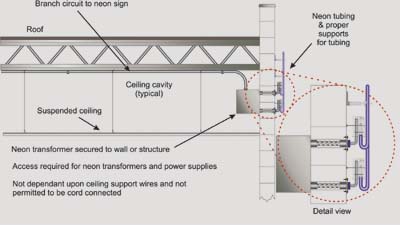
Figure 2. Neon transformers and power supplies are permitted above suspended ceilings where not supported by the ceiling grid system and appropriate access is provided to the transformer or supply
Locating the transformer or power supply is an inherent part of effective design using ingenuity. The location of the transformers is critical in the tube loading and selection process. The Code addresses this generally in requiring the transformer to be as near to the lamps as practicable to keep the secondary conductors as short as possible [600.21(B)]. Maximum lengths are specified in the Code for neon secondary circuits, which will be covered in the next article in this series.
Another important aspect of the location is accessibility. The transformer must be accessible for the installer, the inspector, and service personnel. Unlike the general requirement for standard building power transformers, which are required to be readily accessible, the neon transformer or power supply only has to be accessible. Definitions can help one establish the key difference between the two terms. Basically, the neon transformer can be located in areas where it could be accessed by ladders or other portable means. Service and repair personnel see the benefits of properly located transformers and power supplies and endure the hardships of installations that do not provide proper access or adequate working spaces for this type of equipment.
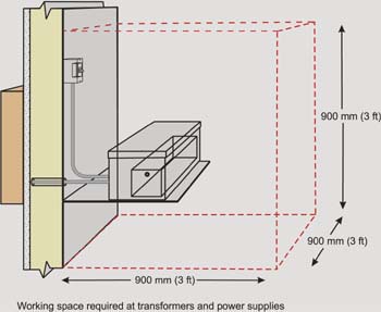
Figure 3. Adequate working space at remote neon transformers and power supplies is required
The NEC includes requirements for adequate working space about electrical equipment that is likely to require examination, adjustment, servicing, or maintenance while energized. Minimum working space is generally 750 mm (30 in.) in width, and not less than 900 mm (3 ft) from the front of the equipment enclosure. It is interesting to note that within Article 600 specific working space is required to be provided at each ballast, transformer, or power supply or its enclosure where it is not installed in a sign. Minimum space to be provided is not less than 900 mm (3 ft) x 900 mm (3 ft) x 900 mm (3 ft). Where located in attics or soffits, an access opening or door at least 900 mm (3 ft) x 600 mm (2 ft) is required to gain access (see figure 3). This is often the case in storefronts and above show windows where the neon or sign is installed to the front or fascia of the building. Sometimes a single access door to these spaces is acceptable, but where the transformers or power supplies are remote from the access opening, suitable passageway and walkways are required. This requirement of the Code is far easier to comply with in new construction than in existing buildings, but keep in mind the NEC does not differentiate here. Electrical safety and safety of the worker is important here [NEC 600.21(D) and (E)].
Another popular location for remote neon transformers and power supplies is above suspended ceilings. The ceiling grid cannot be depended upon for support, which means transformers and power supplies must be securely fastened to the structure in another fashion. Cord- and plug-connected transformers or power supplies are not permitted above suspended ceilings (see figure 2).
Grounding and Bonding
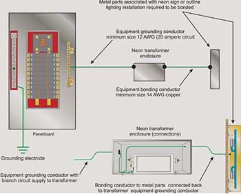
Figure 4. Connections of primary branch-circuit equipment grounding conductor and secondary circuit bonding conductor at transformer enclosure
Understanding grounding and bonding is essential to safe neon installations. Grounding the equipment as required establishes a reference to earth on the metal equipment associated with the sign or outline lighting system. This is accomplished when the equipment grounding conductor with the branch circuit is connected to the transformer or power supply. All metal parts associated with the neon sign or outline lighting must also be bonded together and connected back to the transformer enclosure where the equipment grounding conductor of the branch circuit is connected. This accomplishes two tasks. It puts all metallic parts associated with the sign at the same potential and bonds the metallic parts and components to the equipment grounding conductor of the branch circuit feeding the transformer. This, in turn, puts the bonded metal parts at earth potential (ground reference). Ungrounded metal parts or metal parts that are not bonded and are located in close proximities to high voltage secondary circuits can start to rise in potential owing to capacitance coupling effects. This can lead to potential shock hazards and fire hazards that can result from tracking, etc. A properly grounded and bonded system minimizes these potential hazards and enhances overall electrical safety. [Figure 4]
Proper Loading
The Code addresses the loading of neon transformers in a general nature only. This is left as a primary responsibility of the installer to ensure that the design of the system is such that the right amount of tubing is being supplied by the appropriate transformer or power supply. Basically the length of tubing, the diameter and type of gas used have to be married to the appropriate transformer so that a continuous overcurrent beyond the design loading of the transformer will not result. Transformer manufacturers can provide the tube footage charts for use in design of these systems. Once again, this should be done in the design and planning stages of a neon system installation [NEC 600.41(A)]. There are occasions where the inspector should verify that the proper transformer is being used. A good indication that transformers are underloaded or overloaded is a pattern of service callbacks to keep replacing transformers that continue to fail.
Connections to Transformer
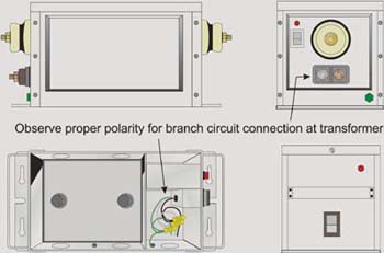
Figure 5. Transformer terminals indicating specific connection terminals for the grounded (neutral) conductor and the ungrounded (hot) conductor
Connections are important parts of any electrical installation. Generally, if failure is going to happen, it usually starts at connection points or terminations. It is rare for failures to start in the middle of a conductor between terminals, but that is is not to say it cannot happen. When the transformer is installed one of the last steps prior to testing the system is checking the connections at the transformer. Primary branch-circuit connections and secondary connections are required. In transformers within integral enclosures, there are usually separate compartments for primary and secondary connections. The integrity of the terminal connections is important. Try to avoid loose connections or connections with devices not intended for such use as they will eventually spawn failure in the system. Where the transformer is field-installed with a suitable enclosure, both secondary and primary conductors are in the same enclosure and attention must be focused on the minimum spacing required between them. A minimum spacing of 38 mm (1 ½ in.) between each secondary conductor and all other objects including the branch-circuit conductors is required [NEC 600.32(E)]. Another item to verify is the minimum length of insulation on the conductor where it emerges from the raceway into the enclosure. In damp and wet locations a minimum distance of 100 mm (4 in.) is necessary, and a minimum of 65 mm (2 ½ in.), in dry locations. Suitable secondary conductors should be used. Another important point to verify is that proper polarity is maintained for the primary connection to the transformer as many of the secondary-circuit ground-fault protection units are polarity sensitive (see figure 5). Many are marked to indicate the terminal specifically for the grounded conductor, and some transformers are also sensitive to being connected to a multiwire branch circuit. A multiwire branch circuit is one that includes two or three circuits that share a common neutral conductor (see the definition of multiwire branch circuit in Article 100). It is important to follow the manufacturer’s installation instructions and recommendations.
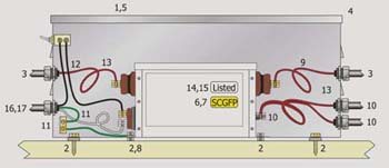
Figure 6. Transformer checklist diagram from Neon Lighting, page 230
As with any electrical installation, there are unique situations or conditions that will be encountered in the field that are not specifically addressed in this article. General requirements and more common elements for field-installed transformers and electronic power supplies have been provided. Also included in this article is a helpful diagram and checklist for these types of installations derived from Neon Lighting, IAEI’s new book. [Figure 6] The checklist serves as a basis for installers and inspectors and might not be totally inclusive.
Safe electric signs, neon, and outline lighting systems are the desire of the installer and the inspector. Working together and effective communication are the keys to attaining safe neon installations. Education is the key to understanding these systems and installations and to becoming more capable of properly applying Code rules to them. The next article in this series provides a review of the secondary conductor installations and wiring methods from the transformer output hubs to the tubing electrodes.