Section 250.30(A) has been reorganized and restructured to provide a more logical layout and improve clarity for users as a result of the work of a task group to achieve those primary objectives. Table 1 cross-references and outlines the new arrangement of this section and provides a comparison between how this section was organized in the 2002 NEC and how it is structured for the 2005 NEC. Various technical changes were also accepted during this cycle and were incorporated into the rewrite in the comment stage of the 2005 NEC development process [ROP 5-78, ROC 5-52].
The sizing requirements for equipment bonding jumpers have been clarified to reference 250.102(C) which resolves sizing conflicts where the derived phase conductors are installed as parallel secondary conductors. The methods of connection for the grounding electrode conductor taps to the common grounding electrode conductor have been revised to be consistent with the methods permitted by the same concept allowed under the provisions of 250.64(D) for services. A clarification has been incorporated into Section 250.30(A)(7) to indicate that any of the electrodes in 250.52(A) shall be permitted to be used where structural metal building frame electrodes or where a metal water pipe grounding electrode is not available. The structural metal building frame bonding and metal water piping bonding requirements in this section have been relocated under 250.104(D). The revisions to this section more clearly address grounding electrode conductor(s) requirements for individual separately derived systems and the common grounding electrode conductor concept for multiple separately derived systems as separate provisions in their own respective subsections.
Various additional technical changes were also incorporated into the reorganization and are as follows:

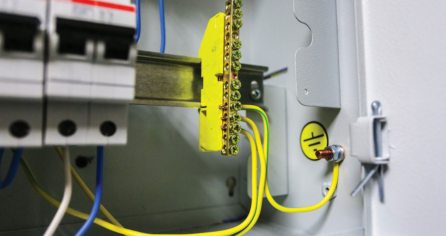
Figure 1. System bonding jumper is the connection between the grounded conductor and equipment grounding conductor at a separately derived system
(A)(1). The term system bonding jumper has been incorporated into 250.30(A)(1) and replaces the term bonding jumper. “Bonding Jumper, System. The connection between the grounded circuit conductor and the equipment grounding conductor at a separately derived system.” Section 250.28 has also been revised to correlate with this revision and a new definition of system bonding jumper has been introduced and accepted into Article 100 [ROP 5-80, ROC 5-48] (see figure 1).
(A)(2). Equipment bonding jumper requirements have been relocated here from 2002 Section 250.30(A)(5). In addition to being relocated under the reorganization, a technical change was accepted to change the reference to 250.28(A) through

Figure 2. Sizing requirements for equipment bonding jumpers or the wire type between the source enclosure and the first system enclosure reference Section 250.102(C)
(D) for minimum sizing to now reference 250.102(C). The change was needed here to allow sizing rules for equipment bonding jumpers installed with conductors run in parallel from separately derived systems and installed in separate raceways. The reference to 250.28 for sizing was limited in application to those installations where all conductors were installed in a single raceway [ROP 5-102] (see figure 2).
(A)(3). No changes other than to renumber 2002 NEC subdivision 250.30(a)(2)(a) to 250.30(A)(3) and to change the heading of the section to “Grounding Electrode Conductor, Single Separately Derived System.”
(A)(4). This is the location for the requirements for multiple separately derived systems that are grounded by utilizing the grounding electrode conductor tap concept previously located in 2002 Section 250.30(A)(2)(b). The heading of this section is now titled “Grounding Electrode

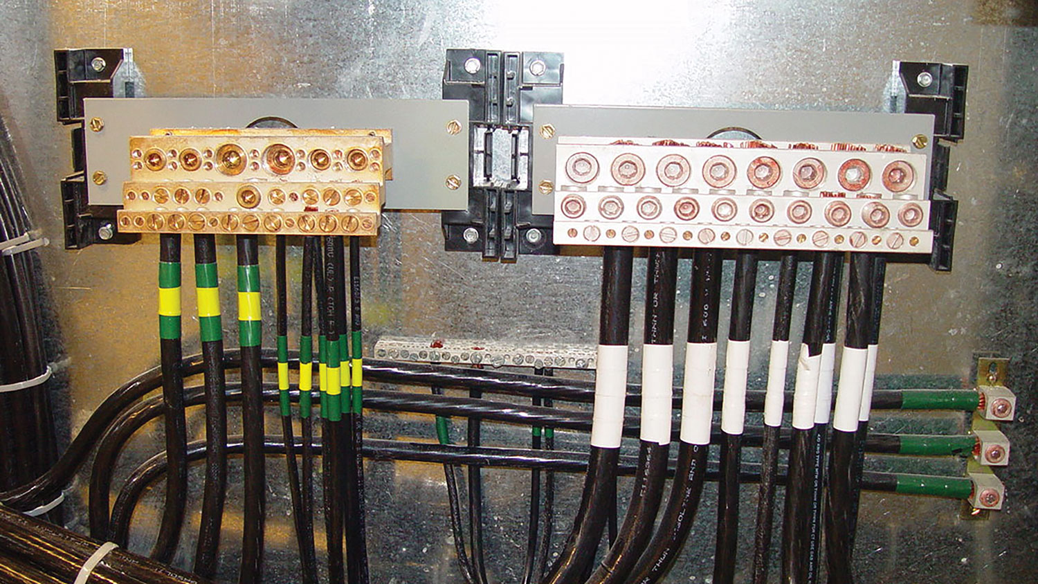
Figure 3. The minimum size of the common grounding electrode conductor must not be smaller than 3/0 copper or 250 aluminum or copper-clad aluminum
Conductor, Multiple Separately Derived Systems” under the reorganization. The changes to this section include presenting the information in a list format as appropriate per NEC Style Manual (3.3.1.2). The rules for sizing the common grounding electrode conductor, sizing the grounding electrode conductor taps, the connection requirements, and installation requirements now all fall under this subdivision in this section. Where the common grounding electrode conductor tap concept is utilized, the minimum size of the common grounding electrode conductor must not be smaller than 3/0 copper or 250 kcmil aluminum as a result of this revision. It should be noted that various discussions led to consensus by the technical committee over this more restrictive sizing requirement. The consensus and feeling were that where this concept is employed, it doesn’t take much to reach the maximum required values provided in Table 250.66. It was also felt that having the maximum size required by Table 250.66 would provide reasonable assurances that future installations would not result in an inadequately sized grounding electrode conductor(s). Installers are still permitted to run a single grounding electrode conductor to an electrode in accordance with (A)(3) above [ROP 5-93, ROC 5-61] (see figure 3).

Figure 4. Structural metal framing member and metal piping system bonding requirements located in 250.104(D)
In new subdivision (c), the methods of connection of the grounding electrode conductor taps to the common grounding electrode conductor have been clarified and presented in a list format. The methods permitted have been revised to be consistent with those methods permitted for the grounding electrode conductor tap concept currently allowed as an alternative under 250.64(D) for connections of grounding electrode conductors for services. This resolves the conflict between 250.30(A)(3) and 250.64(D) in the 2002 NEC relative to the methods of termination of the grounding electrode conductor taps to the common grounding electrode conductor.
(A)(5). References to 250.64(A), (B), and (C) have been relocated here and provide applicability to grounding electrode conductor installation rules for single systems in (A)(3) and multiple systems in (A)(4). The installation provisions were only applicable to grounding electrode conductors and taps under multiple derived systems in the 2002 NEC.
(A)(6). As revised, this section serves only as a reference into Part V “Bonding” and Section 250.104(D) which is the new location for piping system and structural metal member bonding requirements for separately derived systems. All applicable requirements and exceptions have been relocated and reorganized in this new section under the panel action on Comment 5-149. This is a logical relocation of these requirements because bonding rules are located in Part V of Article 250 and the title of this section is “Grounding Separately Derived Alternating-Current Systems” [ROP 5-196, 5-201, ROC 5-149] (see figure 4).
(A)(7). This section includes the grounding electrode requirements previously located in 2002 NEC 250.30(A)(4) and rewrites item (3) to a new exception under this section. This wording was also revised slightly to include the words “”any of the”” in front of other electrodes to clarify that the requirement was not meant to be inclusive of all the other electrodes in 250.52, just an electrode that would meet the requirement. Another change to this section was to remove the term effectively grounded and revise the section to provide references to the nearest of a either metal water pipe electrode in accordance with 250.52(A)(1) or a structural metal grounding electrode as specified in 250.52(A)(2). These changes reflect efforts to clarify that separately derived systems are required to be grounded by connection to a grounding electrode as specified in 250.52. It should also be noted that a new definition of grounding electrode has been introduced into Article 100 to provide additional clarifications [ROP 5-97]. “Grounding Electrode. A device that establishes an electrical connection to earth.”

(A)(8) Grounded Conductor. The reorganization of this section included relocating the minimum sizing requirements for grounded conductors of separately derived systems to 250.30(A)(8). No technical changes were made to this section other than to renumber the section under the reorganization.
Section 250.30(B) is not affected by any of the revisions to 250.30(A).
The primary source of recommended changes that resulted in the reorganization of Section 250.30(A) includes Proposal 5-78 and Comment 5-52. This article includes coverage of action taken on those recommended changes through April 2004. The 2005 NEC process is still ongoing and further action taken during the May 2004, NFPA Annual Meeting and World Conference in Salt Lake City, Utah, could have an impact on the final wording in 250.30(A).


Find Us on Socials