Maximum Tension
Since the National Electrical Safety Code (NESC) minimum vertical clearance between conductors at supports and between the conductors and ground are a function of the sag of the conductors, some utilities might choose to reduce the sag by installing their aerial conductors at the highest tension for which they are allowed without exceeding the NESC limits. By limiting the conductor sags, the structure heights can be reduced and/or the spans can be increased, both of which reduce the cost of construction. What is the maximum tension? The NESC in Rule 261H, page 179, limits the tension of open supply conductors and overhead shield wires to 60 percent of the rated breaking strength (RBS) under the loading conditions specifi ed in Rule 250B, Table 250-1. For example, in the Heavy Loading District, the 60 percent limit is with the conductor at 0°F, with one half inch of radial ice and a 4 Lb./Sq. Ft. wind (about 40-mph wind). The same rule also limits the initial unloaded tension at 60°F to 35 percent of the RBS and the fi nal unloaded tension at 60°F to 25 percent of the RBS.
Safety Factor
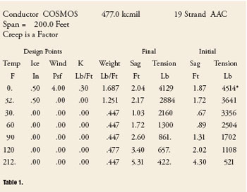
Table 1
Since the NESC requirements are maximums, it is important to use some safety factor in the design to insure that the design tensions do not violate the NESC requirements. To do this, most utilities install their conductors at less tension than the NESC maximums. One approach might be to limit the tensions to 90 percent of that allowed by the NESC. The resulting sag/tension computer program printout might then look like the following for a 200 foot span of 477 AAC “COSMOS” conductor in the NESC heavy loading district (see table 1).
Note that the maximum tension is 4514 lb. The stringing sags and tensions are the initial sags and tensions at 30°, 60°, 90°, and 120°F. The crew installing the conductor usually extrapolates between the four temperatures to determine the stringing sag/tension corresponding to the actual conductor temperature at time of tensioning. The maximum sag is 5.31 feet, the final sag at the conductor’s maximum operating temperature. In this example, the utility has chosen 212°F as the maximum operating temperature. For further information on conductor maximum operating temperatures, see my article on “Conductor Ampacity” in the March/April 2004 IAEI News and my article “Conductor Hyperthermia” in the July/August 2002 IAEI News. Depending upon the construction standard that a utility uses for dead-ending conductors, there might be further limitations on the conductor tension based upon the rated strength of the dead-end hardware and anchoring system. In areas where the soil strength is low for example due to moisture or sand, keeping the conductor tensions lower improves reliability because it makes the anchoring system strength less critical. Is a 10 percent safety factor enough to insure that the NESC maximum tensions are not exceeded under all conditions? To answer this question, we have to look at what conditions effect conductor tension.
Ruling Span
Limiting the tensions to 90 percent of that allowed by the NESC might be fine if all the span lengths between dead-ends of a proposed line are the same. For transmission lines being constructed across open land for great distances, keeping the span lengths the same is usually achievable. However, for most distribution line construction along highways and rear lot lines, keeping the span lengths the same can be difficult. In states where utilities have to get permission from property owners to install poles, the property owners prefer the poles be installed at the side property lines rather than in front of their houses. Since the property widths along the highway may vary greatly, the utility is forced to install poles with diverse span lengths. To better understand how to deal with spans of different length, let’s consider a simple example. A developer has constructed a new road extending 1,184 feet off of an existing road and is selling off property on both sides of the new road for the construction of houses. The lot sizes vary greatly because of the terrain and natural features like streams. To serve the new houses, the utility decides to install the poles at the side property lines along the new road. Not every property corner has a pole. Some spans cross two lots. The resulting design consists of eight spans; 140′, 135′, 124′, 50′, 200′, 275′, 150′, and 110′ in length. If we run a sag/tension program for each of the span lengths and limit tension to 90 percent of the NESC limits, we will find that the final tensions vary greatly span to span even though the tension limits are the same. The final tensions are different because the span lengths are different. To reduce construction time and cost and to reduce the differences in tension from one span to the next, the industry accepted method for stringing the conductors over the eight spans is to string them all at the same time at the same tension. Since we want to install the conductors at the same tension for all the spans, what tension do we use? The industry accepted method to determine the tension to be used for all the spans is to calculate a weighted average of the span lengths. The weighted average is called the “ruling span.” The ruling span is the square root of the sum of each span length cubed divided by the sum of the spans.
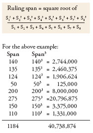
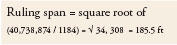
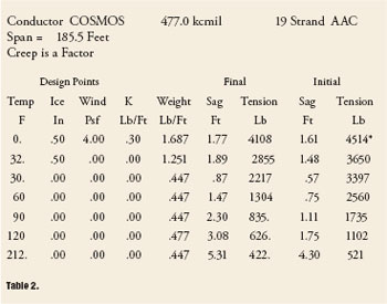
Table 2
We then run a sag/tension computer program on the ruling span to determine the stringing tensions to be used for all the spans. The resulting sag/tension printout might look similar to the information in table 2.
Note that the stringing tensions that would be used for all the span lengths are the initial tensions at 30°, 60°, 90°, and 120°F from the above printout. Again, the crew installing the conductors will have to extrapolate between the four temperatures to determine the stringing tension corresponding to the actual conductor temperature at time of tensioning.
Effect on Tension
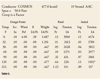
Table 3
If we run a sag/tension program for each of the diff erent span lengths using the initial tensions from the above ruling span printout, we would fi nd that spans shorter than the ruling span have less sag and higher tension than the ruling span and spans longer than the ruling have greater sag and less tension than the ruling span. Since the shortest span will have the highest tension, to insure that the design tensions do not exceed the NESC maximums, we have to run the sag/tension computer program on the shortest span length (50′) limit-ing the initial tension at 120°F to 1102 lb. Note that I have chosen the conductor stringing temperature to be 120°F. I did this because the final sag and tension is also a function of the temperature of the conductor when it is tensioned. Stringing the conductors at 120°F is the worst case scenario. Spans shorter than the ruling span will have higher tensions if tensioned at 120°F. Spans longer than the ruling span will have greater sag if tensioned at 120°F. The resulting sag/tension program printout might look like table 3.
Note that the initial tension of 2977 lb at 60°F exceeds the NESC maximum tension of 35 percent of RBS (2926 lb). This means that the 10 percent safety factor we assumed at the beginning is not enough for this application. Some utilities limit the initial conductor tension to 50 percent, instead of 60 percent, of the rated breaking strength under the loading conditions specified in Rule 250B, the initial conductor tension at 0°F, instead of at 60°F, to 35 percent of the RBS, and the final conductor unloaded tension at 0°F, instead of at 60°F, to 25 percent of the RBS.
Effect on Sag
Since most NESC clearances are a function of the sag of the conductor and spans longer than the ruling span have greater sag, it is important to determine the actual sag of the longer spans for calculation of the clearances for the longer spans. When the tension limits used to design a line are close to the NESC tension limits, ruling span has very little eff ect on the sag of the spans that are longer than the ruling span.
For example, consider the eight span example discussed above. If the tension of each span were limited to 90 percent of the NESC limits, the 212°F final sag of the 275′ span would be 7.75 feet. If we install the 275′ span at the same initial tension as for the 185.5 foot ruling span, the 212°F final sag would be 7.79 feet. When the tension limits used to design the line are considerably lower than the NESC limits, ruling span does have a signifi cant eff ect on the sag of spans that are longer than the ruling span. For example, if the tension limits of the same eight span example discussed above were limited to 50 percent of the NESC limits, the eff ect of ruling span on the 275-foot span would increase the 212°F final sag by almost 11 percent.