Revisions to the NEC are inevitable, and given the unique and important nature of this electrical safety standard, very necessary. The NEC development process is ever dynamic and ongoing, because new technologies are continuously entering the electrical market and code rules must be developed or revised to address electrical safety concerns related to these new materials, equipment, emerging methods or technologies. There were 3,688 proposals, including all technical committee proposals, to change NEC-2008. These proposed changes were acted on by the technical committees at the Report on Proposals (ROP) meetings held in January 2006. This article provides an overview based on code-making panel actions taken on the proposals in the first stage of the development process.
These changes could be affected by subsequent CMP actions on public comments to the proposed revisions.
NFPA’s Report on Proposals includes all proposed changes and related technical committee actions and statements, and is published for public review and comment. Public comments to proposed changes are due to NFPA by October 20, 2006 (5:00 P.M. EST). The development process is an open consensus process in which involvement by everyone is encouraged. Forms for submitting comments are provided on the NFPA website and in the back of the Report on Proposals.
This article is Part I of a series that visits some of the more significant revisions proposed and accepted for NEC-2008.
Code-Wide Revisions
A few revisions were accepted that affect the entire NEC. Three such changes include (1) procedural changes in how the definitions of words and terms are handled by the technical committees, (2) grounding and bonding definitions and terminology revisions, and (3) two new definitions of the terms neutral conductor and neutral point.
Change in Procedures
The NEC-2008 development process included a shift in responsibility for any technical definitions that fall under the scope of responsibility of certain NEC technical committees. Traditionally all of the definitions in Article 100 were the responsibility of code-making panel 1. Action by the NEC Technical Correlating Committee (TCC) results in each code-making panel being responsible for definitions of words and terms that are under its responsibility, but these definitions will continue to be located in Article 100. Definitions that are general in nature will continue to be assigned to code-making panel 1. This change will result in more accurately defined words and consistent correlation of terms throughout the NEC.
Grounding and Bonding
Terms and Rules
A task group was assembled to explore several significant issues regarding grounding and bonding terminology used the Code. The definitions affected by the work of the task group are as follows:
Bonding (Bonded)– revised
Grounding Electrode Conductor– revised
Grounding Conductor, Equipment– revised
Grounding Electrode– revised
Ground– revised
Grounding (Grounded)– revised
Grounded, Effectively– deleted
Ungrounded– new
Where revisions were necessary, the task group developed and submitted proposals to each NEC technical committee. In many cases, revisions provided specific direction for users. The changes in one instance resulted in changing the term shall be grounded to the wording “shall be connected to an equipment grounded conductor” where that was the original intention of the requirement.
The definition of effectively grounded was deleted because the term is subjective and has no specific parameters for making determinations as to whether or not something is effectively grounded. Instances where it was used in previous editions of the Code have been revised to remove the word “effectively” from the phrase.
New Definitions of Neutral Conductor and Neutral Point
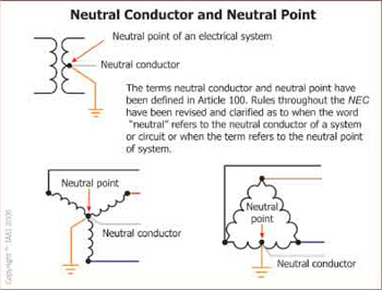
Figure 1. Neutral conductor and neutral point are defined
These definitions have been incorporated into Article 100 to differentiate between a neutral conductor of a system and a neutral point (termination point for neutral conductors) within NEC rules where the terms are used (see figure 1).
Aneutral conductor is intended to carry current under normal operation. In power systems, the neutral conductors are typically the grounded conductor, but not all grounded conductors are neutral conductors.
Aneutral point relates to a common connection point for a neutral conductor connection at the source or system windings.
The rules throughout the NEC that include the word “neutral” have been clarified to be specific to either the neutral conductor or the neutral point of a supply system.
Chapter One – General
Article 100 Definitions
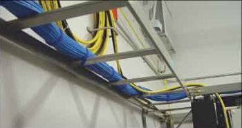
Figure 2. Example of bundled cables
Several definitions in Article 100 have been revised, and a few new definitions have been added.
Bundled.Cables or conductors that are physically tied, wrapped, taped or otherwise periodically bound together. [Relocated from 520.2 to Article 100, see figure 2]
Clothes Closet.A non-habitable room or space intended primarily for storage of garments and apparel. [New definition, see figure 3]
Equipotential Plane.An area where mesh or other conductive elements are embedded in or
Figure 3. Clothes closet
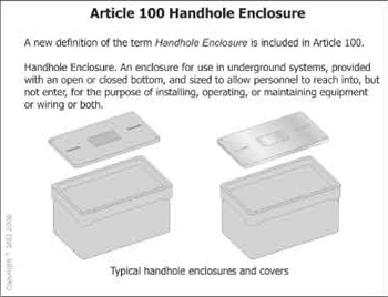
Figure 4. Handhole enclosure defined
placed under concrete or other conductive surface, are bonded together and to all metal structures and fixed nonelectrical equipment that may become energized, and are connected to the electrical grounding system. [Incorporates two concepts into one common term]
Handhole Enclosure.An enclosure for use in underground systems, provided with an open or closed bottom, and sized to allow personnel to reach into, but not enter, for the purpose of installing, operating, or maintaining equipment or wiring or both. [Requirement of identification removed from definition, see figure 4]

Figure 5. Kitchen defined
Kitchen.
An area with a sink and permanent facilities for food preparation and cooking [New definition, see figure 5]
Neutral Conductor. The conductor connected to the neutral point of a system that is intended to carry current under normal conditions. [New definition, see figure 6]
Neutral point. The common point on a wye-connection in a polyphase system or midpoint on a single-phase, 3-wire system, or midpoint of a single-phase portion of a 3-phase delta system, or a midpoint of a 3-wire, direct current system [New definition, see figure 7]
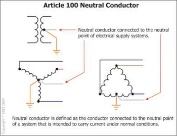
Figure 6. Neutral conductor of a system
FPN: At the neutral point of the system, the vectorial sum of the nominal voltages from all other phases within the system that utilize the neutral, with respect to the neutral point, is zero potential.
Qualified Person.One who has skills and knowledge related to the construction and operation of the electrical equipment and installations and has received safety training to recognize and avoid the hazards involved. [Revised definition, see figure 8]
Article 110 Requirements for Electrical Installations
Revision: 110.16 Flash Protection
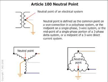
Figure 7. Neutral point of a system
Electrical equipment such as… shall be field marked to warn qualified persons of potential electric arc flash hazards.
Analysis.Two changes to 110.16 provide additional clarity and allow for more appropriate and consistent application to field installations that qualify for the warning labels required by this section. The first revision broadens the requirement by including all types of equipment that would qualify for the field-applied arc-flash warning labels (see figure 9). Previous requirements of this section were limited only to the types of equipment actually identified in the rule. By including the words, “equipment such as” the concept of applicability is expanded to all equipment types that are likely to require examination, adjustment, servicing, or maintenance while energized. This requirement applies to items such as enclosed circuit breakers, some transformers, and other equipment not specifically included in the previous text. The second revision places a specific limitation on the types of dwelling
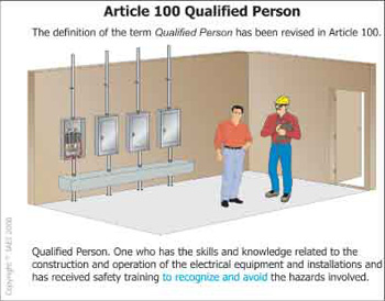
Figure 8. Qualified persons
occupancies covered by these label requirements for equipment. Multiple occupancy dwelling structures such as those in apartment complexes and so forth, where the service equipment and other equipment can be large, definitely qualify for the arc-flash warning labels. The arc-flash warning label requirements do not apply to one- and two-family dwelling units, but arc flash hazards are present in those installations and electrical safety work practices should be followed regardless of the type of occupancy in which the equipment is installed. This rule only addresses where field-applied arc flash warning labels are required. The fine print notes have not been affected by these changes, and still provide appropriate references to other applicable standards that provide relative information about
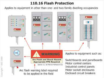
Figure 9. Arc-flash warning label requriements
safe work practices and guidelines for designing safety signs and labels for equipment.
New Section: 110.20 Enclosure Types
Enclosures …shall be marked with an Enclosure Type number as shown in Table 110.20.
Analysis.Concepts introduced during the 2005 NEC development process cycle ultimately led to creating a new Section 110.20 and relocating existing Table 430.91, which includes enclosure type designations and information about their use, to this section (see figure 10). The information within the relocated table remains essentially the same. The table is now identified as Table 110.20. Electrical enclosures in addition to the enclosures used for motor applications as covered by Article 430 are also required to be suitable for the environment in which they are
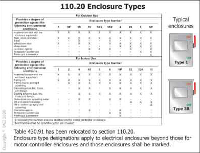
Figure 10. Enclosure types
installed. The effect of this change provides consistency between the UL General Information for Electrical Equipment Directory (White Book) category (AALZ) and the NEC, which apply generally to all electrical equipment, not just equipment associated with motor installations covered by Article 430. Relocating requirements of 430.91 and Table 430.91 into general application Article 110 and specifically indicating the types of equipment to which the requirements apply add clarity. All of the equipment types in the list are required by existing industry product standards to use a Type number marking.
Revision: 110.22. Identification of Disconnecting Means
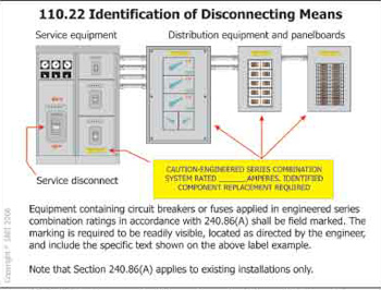
Figure 11. Field labels are required for engineered series combinations of overcurrent protective devices
…. The marking shall be readily visible and state the following:
CAUTION — ENGINEERED SERIES COMBINATION
SYSTEM RATED _______ AMPERES. IDENTIFIED
REPLACEMENT COMPONENTS REQUIRED.
FPN: See 240.86(A) for interrupting rating marking for end-use equipment.
Analysis.Section 240.86 was revised in NEC-2005 to include an alternate method of applying a series rated combination of overcurrent devices that is selected under engineering supervision for existing installations. This alternative provided in 240.86(A) applies to existing installations only and provides a method to allow older existing electrical equipment to remain, where the overcurrent protection is coordinated and selected for the design and application by a licensed professional engineer engaged in the design and maintenance of electrical systems and installations. The primary differences between the requirements in 240.86(B) are that the series combinations covered by the requirements in 240.86(B) are listed and tested devices for use in series rated combinations. The alternative in 240.86(A) allows for a selected engineered design consisting of coordinated overcurrent protection that provides the required protection for equipment in such applications that meets the general requirements of 110.10. The revision to 110.22 incorporates a field-applied labeling requirement for existing equipment that is applied in an engineered series rated combination covered by 240.86(A) [see figure 11]. The new requirements for series rated combination systems labeling parallel the current field-marking rules for listed and tested series rated combinations. The key element of the label is that it includes the wording “engineered series rated combination” and the specific equipment requiring the labels will be as directed by the engineer responsible for the design under this alternative.
Revision: 110.26(C) Large Equipment
Analysis.Action by CMP-1 restores the dimension 1.8 m (6 ft) that applies to the equipment
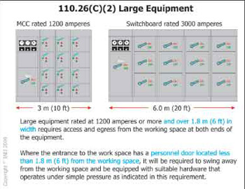
Figure 12. Size and rating of the equipment are both factors in the requirement for two entrances and egress paths from the working space
rated at 1200 amperes or more that constitutes large equipment covered by this section. The requirement for physical size was removed during the 2005 NEC development process, which presented some challenges for meeting the requirements for two entrances and egress paths from some types of equipment where it was not practical or, in some cases, not possible. For example, a 1200-ampere panelboard that is 900 mm (3 ft) in width would be required to meet the two-entrance requirement as provided in NEC-2005. By restoring the requirement for physical size, building and engineering designs are less impacted by a requirement that is not necessary in all cases. This rule, in addition to many others, has to include minimum dimensions and energy levels that serve as a starting point regarding applicability. Large equipment with lower ampacity ratings, such as 800-ampere or 1000-ampere rated switchboards, and so forth, present similar challenges and safety concerns relative to whether two entrances or egress means are required (see figure 12). The second change inserts a specific distance from equipment at which a personnel door that provides access and egress from the working space must meet certain operational and physical characteristics. Personnel doors located less than 1.8 m (6 ft) from the working space mandated by this section will be required to swing away from the working space and be equipped with suitable hardware that operates under simple pressure as indicated in this requirement.
Revision: 110.33 Entrance to Enclosures and Access to Working Space
(A) Entrance. …. a personnel door(s) that is less than 3.7 m (12 ft) from the working space, the door(s) shall open in the direction of egress and be equipped with panic bars ….
(B) Access to Working Space. Permanent ladders or stairways shall be provided to give safe access to the working space around electric equipment installed on platforms, balconies, or mezzanine floors or in attic or roof rooms or spaces.
Analysis.This revision clarified which enclosures are covered by the requirements for entrance and egress means. The enclosures in 110.31, such as fenced areas, vaults, rooms, closets, and so forth, are required to meet the entrance and access requirements of this section. The new language in the second sentence of 110.33(A) clarifies that the personnel door(s) requirement applies to the working space and not necessarily the room in all cases. The 3.7 m (12 ft) distance is reasonable and provides for safe egress from the area. Currently, some jurisdictions are applying the requirement where the doors are a considerable distance from the working space, such as in large areas or rooms. These revisions should provide clear direction as to when the door is required to swing away from the working space, and when it must be equipped with simple release hardware. Personnel doors that are located 3.7 m (12 ft) or more from the working space mandated by this section will not be required to meet the physical and operational characteristics of this rule.
Chapter Two – Wiring and Protection
Article 210 Branch Circuits
New Section: 210.4(D) Grouping
(D) Grouping. The ungrounded and grounded conductors of each multiwire branch circuit shall be grouped by wire ties or similar means in at least one location within the panelboard or other point of origination.
Exception: The requirement for grouping shall not apply if the circuit enters from a cable or raceway unique to the circuit that makes the grouping obvious.
Analysis.This new section requires grouping the grounded conductor of multiwire branch
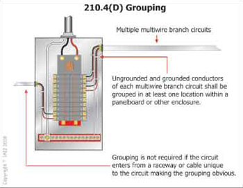
Figure 13. Multiwire branch-circuit conductors must be grouped at least once in enclosures such as panelboards or other equipment
circuits with the associated ungrounded conductors of the same multiwire branch circuit. These conductors must all be grouped together at least once at a location within the panelboard or equipment where the conductors of the circuit originate (see figure 13). This new grouping requirement should provide more ready means for workers and inspectors to identify the grounded conductor of a mutliwire branch circuit within the equipment where the circuit originates. The new exception to this rule relaxes this requirement where the entry of the circuit conductors of a cable or raceway makes the association obvious without additional grouping. Examples of installations qualifying under the exception include MC or AC cable assemblies or a raceway that contains only the conductors of the multiwire branch circuit. This change will result in all associated conductors of a multiwire branch circuit, including the grounded conductor, being physically grouped together at least once by wire ties or other means within the branch-circuit overcurrent device enclosure to allow for ease of visual recognition. Installers sometimes use wire ties to group multiple conductors of several branch circuits together while lacing and dressing the circuits in the equipment during the conductor termination process. This practice makes it difficult to identify which grounded (neutral) conductor is associated with the ungrounded conductors of the same multiwire branch circuit within the equipment. The new grouping rule should allow installers and inspectors to more readily identify multiwire branch-circuit conductors within the equipment where these conductors originate, enhancing safety.
Revision: 210.8(A) Dwelling Units
The two existing exceptions to 210.8(A)(2) have been deleted. Additional text added to 210.8(A)(5) indicates that any receptacles installed under the exceptions to 210.8(A)(5) shall not be considered as meeting the requirements of 210.52(G).
Analysis.The exception for receptacles that are not readily accessible has been deleted because the concept of being “readily accessible” is too vague and can lead to inconsistencies in how the requirements are applied. A garage door opener might not be readily accessible to short persons, but very well could be accessible to persons that are taller. The shock protection of this requirement should apply to all persons. Exception No. 2 has been deleted to establish consistency with the GFCI receptacle requirements in 210.8(A)(7) that were expanded in NEC-2005. The product safety standards for appliances covered by this exception require appliances to be manufactured with insulation dielectric leakage levels that do not exceed 0.5 mA. This level of leakage current is far below the 4–6 mA leakage thresholds of Class A ground-fault circuit interrupters manufactured to UL Standard 943. There clearly is no longer a need for either of these exceptions. Deleting the two exceptions creates consistency between the requirements in 210.8(A)(2) and 210.8(A)(7) and enhances the level of shock protection for persons where leakage levels in appliances could develop and present shock hazards that under the previous allowances of the exceptions would otherwise go undetected. Protection by ground-fault circuit interrupters is not related to the location of the receptacle. If cord- and plug-connected utilization equipment (appliances exempted by the previous exceptions) has abnormal or excessive leakage current levels that will trip the GFCI, protection should be provided. Based on the information in the applicable product safety standards, the maximum leakage current for typical cord- and plug-connected equipment (appliances) is 0.5 mA. The trip range for Class A GFCI protective devices is 4–6 mA. In order for this utilization equipment to trip a GFCI protective device, leakage current levels would have to reach 8 to 12 times that permitted by the product standard, creating safety concerns. The fact that the receptacle is not readily accessible will have no impact on the shock hazard protection for persons encountering the utilization equipment.
Revision: 210.12(B) Dwelling Units
Analysis.These revisions simply expand the requirements for arc-fault circuit interrupter

Figure 14. All 15- and 20-ampere branch circuits in dwelling units are required to be protected by arc-fault circuit interrupter protection.
protection to all 15- and 20-ampere branch circuits installed in dwelling units (see figure 14). CMP-2 expanded the AFCI protection requirements to branch-circuit outlets that supply dwelling unit bedrooms in NEC-2005 as a means to enhance safety and gain experience putting the application in an easily defined and limited area. Arc-fault circuit interrupters have been proven effective in detecting and clearing arcing conditions or events in wiring systems before damage and loss could occur. This is the principle objective of this type of protection. Experience has shown that AFCI protective devices also detect numerous wiring errors and, in addition, they have found wiring damage and equipment damage that could have been potential sources of fire where protected only by conventional protection devices. A strong basis for limiting this protection to circuits that supply only dwelling unit bedrooms no longer exists, and the increased protection is needed for other circuits. This expansion will continue the effort to help reduce and minimize fires of electrical origin in dwellings. The second paragraph has been deleted because the effective date for ACFI protective devices coincides with the publication of NEC-2008 and so is no longer necessary. Proposed deadline extensions were rejected by CMP-2, which affirms the panel’s intentions that all AFCI protective devices be combination types as of January 1, 2008.
Revision: 210.62 Show Windows
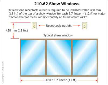
Figure 15
Analysis. More specific location criteria that must be applied to show window receptacle installations are imposed. The new rule requires the receptacle to be located within 450 mm (18 in.) of the top of any show window (see figure 15). This change provides clear direction on how to meet the placement criteria for show window receptacles, while at the same time providing enforcement with a means to apply the rule more consistently to all show windows. This results in receptacles being located for the convenient and practical use for which they were intended, without having to resort to extension cord use, or other remedial means of supplying power for show window applications that can lead to or result in less than safe conditions.
Article 215 Feeders
Revision: 215.10 Exception No. 3
The provisions of this section shall not apply if ground-fault protection of equipment is provided on the supply side of the feeder and on the load side of any transformer supplying the feeder.
Analysis.The revisions to Exception No. 3 clarify where GFPE is required (see figure 16). The
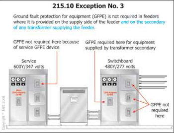
Figure 16
intent is not to require GFPE on a feeder disconnect if that feeder has GFPE protection provided upstream. However, some are misinterpreting that GFPE could be provided on the primary of a transformer to meet this exception. Of course, GFPE on the primary side of a transformer provides no equipment protection to equipment connected to the secondary since the ground-fault on the secondary only returns current to the secondary of the transformer. The objective is to allow relaxing the GFPE requirement for distribution equipment connected to feeders where a GFPE device is supplied upstream of the feeder, at the service equipment for example. When a transformer is inserted in a feeder, essentially this is a new derived system or source. The requirement for ground-fault protection for equipment is related to the size of the equipment supplied by the feeder as indicated in the rule that this exception follows. Current, including ground-fault current, will always try to return to the source. In this case, the source is the transformer. The GFPE on the supply side of such transformers would not function to protect the equipment in accordance with the requirements of this rule because the ground-fault current would not be attempting to return to the service and utility transformer but to the transformer on the supply side of the feeder. This exception does not apply to field installations where the feeder is derived from a transformer supplied from the service equipment on its supply side. Any GFPE on the supply side used to exempt the feeder disconnect from GFPE must be on the load side of the transformer supplying the feeder.
Article 225 Outside Branch Circuits and Feeders
Revision: 225.39 Rating of Disconnect
Analysis.Sections 225.31 and 225.33 address requirements for disconnecting means in feeders
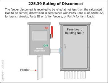
Figure 17
supplying separate buildings or structures, which are similar to those required for service disconnecting means covered in 230.70 and 230.71. Section 230.80 includes methods of establishing a combined rating for installations where multiple disconnects in separate enclosures are used as the service disconnecting means. Disconnecting means is defined in Article 100 and can be a single disconnect or a group of disconnects. Section 225.39 has been revised by adding a new second sentence to clarify that when more that one switch or circuit breaker is used as the disconnecting means for a feeder supplying a separate building or structure, the combined ratings of the switches or circuit breakers used as the service disconnecting means can be added together to achieve the minimum rating required for the disconnecting means (see figure 17). This revision incorporates methods of establishing combined ratings of several disconnects in 225.39 that are similar to the requirements already provided in 230.80 for services.
Article 230 Services
Revision: 230.44, Exception
Analysis.This revision includes specific labeling requirements that clearly indicate where the
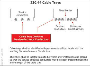
Figure 18
cable tray is being used for service-entrance conductors (see figure 18). The last two sentences were added to ensure that the cable tray containing a barrier separating the service-entrance conductors are clearly identified from feeders and branch circuits installed in the other side of the cable tray. The labels should be visible after the installation of the cable tray since an installer may not be able to differentiate between section/partition of the tray containing the service-entrance conductors and inadvertently install protected conductors with unprotected conductors. Cable trays shall be identified with permanently affixed labels with the wording “Service-Entrance Conductors.”
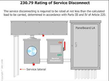
Revision: 230.79 Rating of Service Disconnect
The service disconnecting means shall have a rating not less than the calculated load to be carried, determined in accordance with Parts III and IV of Article 220.
Analysis.These revisions clarify that the rating of the service disconnect is to be not less that the