
Equipment installed in electrical systems generally is required to be grounded. There are some specific exceptions that relax this general requirement of the NEC; but, for the most part, electrical equipment and the normally non-current-carrying metal (conductive) parts of equipment are to be grounded.
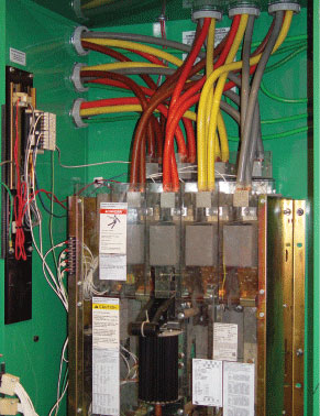
Photo 1. Large electrical feeder circuits are often installed using the provisions for parallel conductor installations contained in 310.4 of the Code.
Performance Criteria
The performance requirements for equipment grounding are provided in Section 250.4(A)(2) for grounded systems, and 250.4(B)(1) for ungrounded systems. This article focuses primarily on the equipment grounding conductor requirements for grounded systems, although they are essentially the same for both grounded and ungrounded systems. Part VI of Article 250 provides the prescriptive rules relating to equipment grounding conductor installations. The requirements in this part of Article 250 provide information about the requirements for equipment to be grounded, types of equipment grounding conductors, sizes of equipment grounding conductors, identification of equipment grounding conductors and connection methods.
The Need for Parallel Conductors
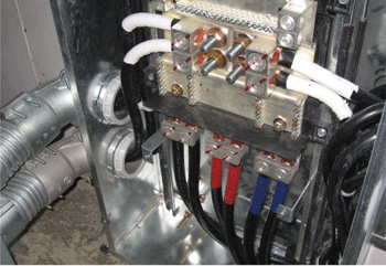
Photo 2. Electrical feeder conductors installed in parallel, supplying a large panelboard
Often in electrical design and installations, there is a need to install feeder conductors in parallel. Where feeders are large in size and ampacity, they quickly reach a point where it becomes impractical to install them using only one conductor per phase and one for the grounded (neutral) conductors. This is where the provisions for feeder conductors installed in parallel come into play. The Code requirements for parallel conductors are provided in 310.4 and the requirements for equipment grounding conductors for parallel conductors are covered by 300.3(B)(1), 310.4, and 250.122(F) [see photo 2]. This article provides a closer look at the requirements for equipment grounding conductors in general, but specifically those equipment grounding conductors for larger feeders installed using parallel conductors.
Rules for Conductors Installed in Parallel
The rules pertaining to electrical conductors installed in parallel are provided in 310.4 of the NEC. Before reviewing the general requirements for conductors installed in parallel, let’s look at what constitutes conductors installed in parallel.
Copper, copper-clad, or aluminum conductors in size 1/0 or larger are permitted to be installed in parallel. This includes the ungrounded phase conductors, conductors of different polarity, grounded neutral conductors and grounded phase conductors. The provision recognizes that multiple conductors can be installed in parallel with one another not to create one conductor, but to create one electrically conductive path (see figure 1). In other words, conductors installed in parallel are electrically connected at both ends creating an electrically conductive path capable of carrying a desired ampacity based on the needs of the design (see photos 1 and 2). Paralleled conductors of each phase, polarity, neutral, or other grounded circuit conductors must meet all the following requirements:
- They must be the same length
- They must be terminated in the same manner
- They must have the same conductor material
- They must be the same size in circular mil area
- They must have the same insulation type
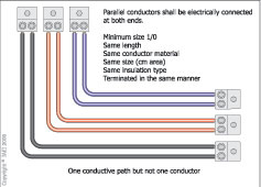
Figure 1. Conductors are installed in parallel to create one larger electrically conductive path, not one conductor.
Where conductors are installed in separate cables or raceways, the raceways or cables are required to have the same physical characteristics, and the same number of conductors in the parallel set must be installed in each raceway. The equipment grounding conductors installed with parallel conductor installations must also meet all requirements above, except for the sizing requirement of 1/0 minimum. The sizing requirements are based on the rules in 250.122(F). These sizing rules are reviewed in detail later in the article.
General Circuit Conductor Installation Requirements
Where equipment grounding conductors are installed with paralleled feeder conductors, the requirements in 310.4 have mandatory application. To develop an understanding of the requirements in 310.4 and 250.122(F), a brief review of the rules in 300.3(B) and 250.134(B) is in order. The requirements in these sections call for all conductors of the circuit, including any grounded conductors and all equipment grounding conductors, to be installed together, typically contained in the same raceway, cable bus assembly, cable tray, trench, cable, or cord. This requirement serves to maintain low impedance levels during normal conditions and abnormal (ground-fault) conditions. To separate the equipment grounding conductors results in increases in inductive reactance, which raises impedance levels. This is one of the primary reasons for installing equipment grounding conductors in each raceway when they are installed in multiple raceways. Under ground-fault conditions, the equipment grounding conductor carries the heavier level of fault current until the overcurrent device opens and clears this event from the system. If there is only one equipment grounding conductor in one of the raceways of the parallel set, the impedance is raised significantly due to inductive reactance. Not installing equipment grounding conductors in each raceway or cable not only violates 250.122(F), but also 300.3(B) and 250.134(B). Of course, any of the equipment grounding conductor types identified in 250.118 can be used for parallel conductor installations. The sizing requirement pertains only to installations where wire-type equipment grounding conductors are installed.
Equipment Grounding Conductor Types
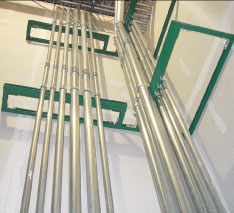
Photo 3. Electrical metallic tubing used as an equipment grounding conductor for a feeder made up of conductors installed in parallel
Section 250.118 provides a long list of acceptable equipment grounding conductors that qualify as an effective ground-fault current path where installed in accordance with all other applicable requirements of the NEC. This section recognizes wire-type equipment grounding conductors as either copper or some other corrosion resistant conductor. It also lists conduit, metallic tubing, metallic cable assemblies, and other acceptable equipment grounding conductors. Where metal conduit is used as the equipment grounding conductor, it must meet the requirements in 110.12 for workmanship, supporting and securing requirements in chapter 3 for the particular wiring method used, and they are required to be of the same physical characteristics as provided in 310.4 (see photo 3).
Sizing Parallel Equipment Grounding Conductors
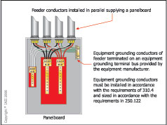
Figure 2. All conductors of the circuit including any grounded conductors and equipment grounding conductors are required to be grouped together in accordance with 300.3(B).
Where electrical conductors are installed in parallel and are all contained in the same raceway or other enclosure such as a wireway or auxiliary gutter, the sizing rules for equipment grounding conductors of the wire-type are quite simple. Just use the rating of the overcurrent device protecting the parallel set and reference Table 250.122 for the minimum size single equipment grounding conductor of the wire-type. Where equipment grounding conductors are installed with conductors in parallel, and they are in separate multiple raceways or cable assemblies, the wire-type equipment grounding conductors are required to run in parallel in each raceway and must meet all the requirements in 310.4 with the exception of the sizing rules (see figure 2).
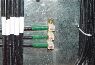
Photo 4. Paralleled equipment grounding conductor connections at equipment
The equipment grounding conductors for parallel runs do not have to meet the requirement of 310.4 that calls for a minimum 1/0 conductor size, because the equipment grounding conductors in each raceway are full size as required by 250.122. The equipment grounding conductors in a parallel installation are not being installed in parallel to create one larger conductive path , as is the case for the ungrounded phase conductors of the circuit and grounded (neutral) conductor if present. See 250.122(F) and 310.4 for the exact Code language that provides this requirement.
Sizing Equipment Grounding Conductors
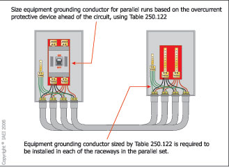
Figure 3. Sizing requirements for equipment grounding conductors installed with feeder conductors in parallel
Sizing rules for equipment grounding conductors installed with parallel runs of conductors are provided in 250.122(F). The equipment grounding conductors installed in separate multiple raceways or cables must be sized based on the rating of the overcurrent device protecting the parallel set of conductors in accordance with Table 250.122 (see figure 3). This means if the overcurrent protective device for a feeder is rated at 800 amperes, the size of equipment grounding conductor (wire-type) cannot be less than 1/0 copper or 3/0 kcmil aluminum or copper-clad aluminum.
Question No. 1: If the size of the overcurrent device protecting a feeder is rated at 1600 amperes, what is the minimum size aluminum equipment grounding conductor (wire-type) required in each raceway of the parallel set?*
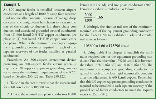
Example 1
Section 250.122(B) also includes a requirement that addresses conductors that are increased in size, such as for voltage drop. Where equipment grounding conductors (wire-type) are installed with conductors in parallel that are installed in separate raceways and increased in size for voltage drop reasons, the equipment grounding conductors must all be increased in size proportionately (see example 1).
Equipment Grounding Conductor Connections
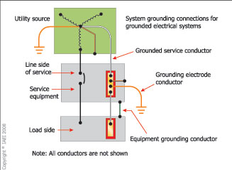
Figure 4. Equipment grounding conductor connections for a grounded system
Equipment grounding conductors are an important component in the effective ground fault current path. One of the most critical points in any electrical circuit is the terminals or connections. This is typically the point at which a circuit failure would occur. The Code requirements for equipment grounding conductor connections are covered in 250.130. This rule addresses the required connections at a separately derived system or service. For a grounded system, the equipment grounding conductor is required to be connected to the grounded conductor and the grounding electrode conductor at the service or at the source of a separately derived system as provided in 250.30(A)(1) (see figure 4). The same rules apply for an ungrounded system, except that there is no grounded conductor in an ungrounded system. In this case, the equipment grounding conductor is connected to the grounding electrode conductor and the enclosure (see figure 5).
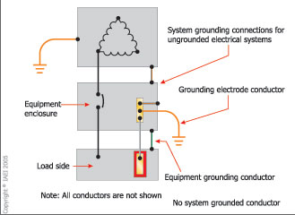
Figure 5. Equipment grounding conductor connections for an ungrounded system
Section 250.8 provides more specific requirements for grounding and bonding conductor connections. This section requires that these connections be made using listed lugs, listed pressure connectors, listed clamps, or other listed means (see photos 4, 5, and 6). This is one of those NEC rules that specifically requires the use of listed equipment.
There is additional information about listed grounding and bonding equipment in the Guide Information for Electrical Equipment (UL White Book) under category (KDER). Another key requirement is found in Section 250.12. Where painted or coated enclosures are installed to which equipment grounding conductors must be connected, the coating is required to be removed to ensure electrical continuity and conductivity, unless the connections are made by using fittings designed to make coating removal unnecessary.
Summary
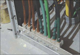
Photo 5. Equipment grounding conductor connections made by listed lugs
The equipment grounding conductor of the grounding and bonding scheme in any electrical system has two primary functions. First, it serves to establish an earth (ground) connection for the equipment. This maintains the equipment at or as close as possible to earth potential. The second function of the equipment grounding conductor is to provide an effective ground-fault current path to facilitate overcurrent device operation during ground-fault events. Where equipment grounding conductors are installed in parallel, the requirements in 250.122(F), 310.4, 300.3(B) and 250.134(B) all apply.
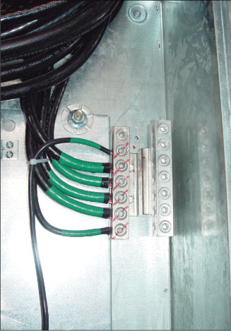
Photo 6. Equipment grounding conductor connections made at a panelboard supplied by a feeder installed with conductors in parallel
Equipment grounding conductors of the wire-type installed in parallel conductor runs must be sized based on the rating of the overcurrent device protecting the parallel set in accordance with Table 250.122. The minimum 1/0 sizing requirement for conductors installed in parallel does not apply to equipment grounding conductors, but all other installation requirements contained in 310.4 apply to those wire-type equipment grounding conductors. The information provided in this article is based on the minimum requirements contained in NEC-2005. As always, be sure to verify with the local authority having jurisdiction for any local rules that may also apply to parallel conductor installations.
* Answer: 350 kcmil aluminum or copper clad aluminum