Grounded Systems Generally Required
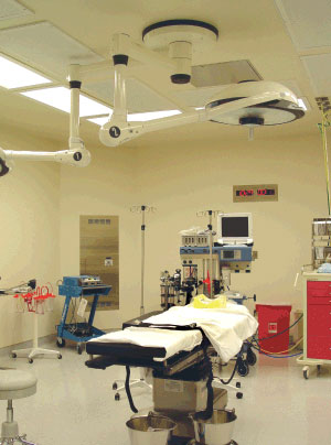
Photo 1. Health Care Facility Room
Grounded Systems Generally Required
Photo 1. Health Care Facility Room
Generally, electrical systems used in power distribution systems for premises wiring are required to be grounded. The NEC includes rules that often make this determination. Some electrical systems are required to be grounded, while other systems are permitted to operate ungrounded (see 250.20 and 250.21). Then there are those systems that are not permitted to be grounded (see 250.22). One such ungrounded electrical system is the isolated power system utilized in health care facilities. This article focuses on some key installation requirements for these systems, and also takes a look at essential elements of installing and inspecting these ungrounded electrical systems.
Brief Look at the History
In early years of health care methods and procedures, the anesthetics utilized were mostly of the flammable types. Even prior to the use of electricity for medical equipment and appliances, the challenges of flammable anesthetics presented themselves often with resultant injuries and many deaths. Explosions and fires were linked to ignition of flammable anesthetics (such as ethylene ether) by open flames of candles as well as static electricity and other sources. The problem had escalated to frequent occurrences of these types of accidents in the health care world. The committee on health care facilities was formed in the 1930s to deal with this as well as many other challenges. This committee work was the initial development of what is now known in the codes and standards world as NFPA 99, the health care code.
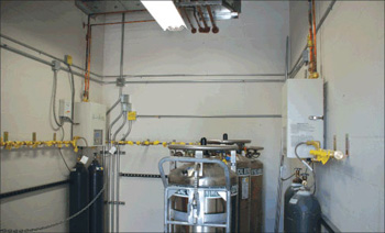
Photo 2. Nonflammable anesthetics in a gas storage room of a hospital
TheNECdealt with electrical installation provisions for health care facilities generally in the early editions of the document. The practice of medicine and medical procedures in health care was also paralleled with the practice and learning stages of the safe use of electrical power in these early times. The ignition component of the fire triangle, and the fire triangle itself were discovered and had to be dealt with in health care facilities as well as in other occupancies. In the early editions of the NEC (1930s through the 1950s), the Code included provisions for health care facilities only generally, but did include a section (5135) on combustible anesthetics under Article 510 on hazardous locations in the early 1950s. In the code cycles to follow, the NEC continued to include information and provisions for combustible anesthetics under Article 510 through the early 1960s. In NEC-1965, Article 517 was formed and titled “Flammable Anesthetics.” That title was changed from “Flammable Anesthetics” to “Health Care Facilities” in development of NEC-1971. Many of the provisions contained in Article 517 at that time were electrical provisions already contained in NFPA 99. Health care facilities electrical rules and provisions were now included as a special occupancy in the NEC, and rules for flammable anesthetics as well as other electrical requirements for health care facilities had arrived.
Use of Isolated Power Systems
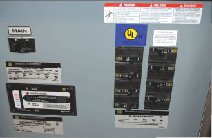
Photo 3. Isolated power systems are required to be listed
Isolated power systems were a method of dealing with flammable anesthetics in early Code rules. By operating the electrical system ungrounded, the arc from a first ground fault is minimized. This type of system helped minimize the hazards of ignition of flammable gases during health care procedures and operations. Other methods of reducing ignition sources, such as static electricity, are conductive operating room floors and equipotential grounding and bonding to reduce the likelihood of current flow across to conductive surfaces that might be at different electrical potentials. Some operating rooms still have evidence of first generation protective techniques utilized in preventing fires and explosions. This evidence might be in the form of the old conductive flooring with the occasional drag chain hanging from old rolling metal operating room tables. Isolated power systems were utilized heavily as one of the primary protection techniques in operating rooms and critical care locations of health care facilities. These systems are still in use, although many of the problems with flammable anesthetics are significantly fewer in numbers. Nonflammable anesthetics have replaced the common use of the flammable types (see photo 2). There are areas and other countries that still utilize the oxygen inspired gases that are flammable and some laboratories in health care facilities might require use of flammable gases. The hazardous (classified) locations associated with flammable anesthetizing locations are still delineated in Article 517. Part IV of Article 517 continues to include the requirements for electrical wiring and equipment in an anesthetizing location of a heath care facility that is classified as a hazardous (classified) location.
Ungrounded System Characteristics
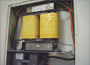
Photo 4. The transformers of isolated power systems are typically of low kVA capacity.
When an electrical system is operated ungrounded, there is no solid reference to ground from any of the conductors supplied by the secondary of such systems. A few key advantages of such systems include minimal arcing effects from a first phase-to-ground fault condition. Another benefit is continuity of service (uninterrupted power) of such systems. A third benefit is reduced shock and electrocution hazards from phase-to-ground contact with such systems. These systems provide an equal and effective form of electrical safety for health care facilities. As with other ungrounded systems, these systems must be monitored and operated by qualified persons. Isolated power systems operate ungrounded, but a line isolation monitor is required to continuously monitor leakage current from each phase conductor supplied by the system as part of this listed equipment. This monitor detects leakage current to ground in the milliamp threshold range of not greater than 5 mA similar to high-impedance grounded neutral systems and ungrounded systems with ground detectors. When the line isolation monitor of an isolated power system provides annunciation of leakage current beyond the acceptable limits, appropriate corrective action is required by qualified personnel. This usually includes discontinued use by medical personnel at first, then corrective actions by facilities maintenance staff thereafter. Common causes for alarm conditions identified by line isolation monitors of isolated power systems include, but are not limited to, equipment or medical appliance insulation failures as well as breakdown on insulating in electrical circuitry supplied by such systems. While breakdown of the insulation of the isolated power-system branch circuits is possible, the monitor usually detects leakage currents when dielectric insulation in equipment or appliances fails. An important protection feature of these isolated ungrounded systems is the continuity of electrical service that they provide even with an insulation failure. This allows the power to remain on for these systems that are supplying life support equipment and other critical care apparatus essential to the well-being of patients receiving treatment in locations supplied by isolated power systems.
Listing Required
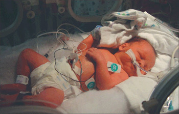
Photo 5. Infant is being kept alive by life support equipment supplied from an isolated power system.
Isolated power systems are required to be listed as indicated in 517.61(A)(2) [see photo 3]. This means the system is listed to an appropriate electrical safety standard (see UL Standard 1049). This also means that specific instructions and guidelines for use will be required for proper installation and inspection of such systems.
A couple of key areas of concern are the dielectric values associated with the branch-circuit conductors supplied by the isolated power system. Since the system is measuring leakage current to ground in the milliamp range, conductor and system insulation are important. This is a primary reason that these listed systems are kept at low kVA transformer ratings, usually below 10 kVA (see photo 4). This helps minimize the amount of leakage capacitance on the secondary side of the isolation transformers used in these systems.
Isolated Power Systems Required
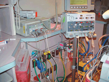
Photo 6. Life support equipment used in a critical care patient location of an intensive care unit
The decision on when to use isolated power systems in health care facilities depends on the patient care area and the characteristics of the electrical system supplying the patient care area. For example, isolated power systems are permitted as an optional protection technique for critical care locations of health care facilities [see 517.19(E)]. This rule became optional in NEC-1996. However, isolated power systems become a requirement and not an option when wet procedure locations, as defined in 517.2, preclude the use of ground-fault circuit interrupters (GFCIs) where interruption by GFCI devices cannot be tolerated (see photos 5 and 6). In this case, the protection technique must be provided by an isolated power system [see 517.20(A) and (B)]. Once the isolated power system becomes a requirement, it must be listed equipment and installed to meet all applicable rules in 517.160.
Wet Procedure Locations
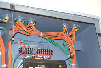
Photo 7. XHHW conductor insulation used on branch-circuit conductors supplied by an isolated power system.
The definition title wet locations in 517.2, under “Patient Care Area,” has been revised for the NEC-2008 to wet procedure location. This revision provides more specific criteria of the wet locations covered by the definition in 517.2 and provides a bit more differentiation from the wet location definition in Article 100. See IAEI’s book, Analysis of Changes NEC-2008 for additional information about this revision.
Isolated Power System Branch-Circuit Conductors
Isolated power systems and their proper installation and use involve specific criteria. Insulation and identification of the branch-circuit conductors is more specific than that allowed in the general rules of the Code. The dielectric insulation resistance values are critical for system functionality. Minimizing the length of branch-circuit conductors and using conductor insulations with a dielectric constant less than 3.5 and insulation resistance constant greater than 6100 megohm-meters (20,000 megohm-ft) at 16°C (60°F) reduces leakage from line to
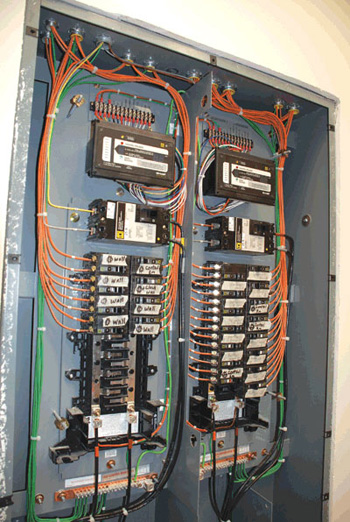
Photo 8. Brown and orange XHHW conductors installed for isolated power-system branch circuits
ground, reducing the hazard current. THHN/THWN typically do not offer these high dielectric insulation resistance values. XHHW is one type of conductor insulation that meets the dielectric insulation values required by these systems (see photo 7). The manufacturer’s instructions and installation guidelines for these systems will often specify the type of conductor insulation required or acceptable for use with the particular system. Sometimes a maximum length for the circuits is also specified. Wire-pulling compounds that have a deterioration effect on the dielectric values of conductor insulation are not permitted to be used when installing these branch-circuit conductors [see 517.160(A)(6)].
Branch-Circuit Color Code Required
The Code does not include a color code for general wiring branch-circuit conductors. However, there is a specific color code required for the branch-circuit conductors supplied by the isolated power system. Section 517.160(A)(5) requires the branch-circuit phase conductors to be orange (for conductor No. 1) and brown (for conductor No. 2) (see photos 8 and 9). Yellow is the required color for the third conductor if a three-phase isolated power system is used.
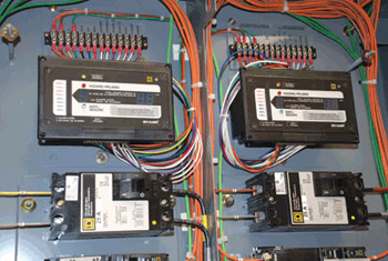
Photo 9. Brown and orange XHHW conductors installed for isolated power-system branch circuits
NEC-2008 Update: As of this writing, Section 517.160(A)(5) has been revised to require that the orange, brown, and yellow conductors used with isolated power systems are now required to be identified with a distinctive colored stripe other than white, green, or gray. See IAEI’s book, Analysis of Changes NEC-2008 for additional information about this revision.
Where the isolated power system branch circuits supply 125-volt 15- or 20-ampere receptacles, the orange conductor is required to be connected to the terminal on the receptacle intended for the grounded conductor (see photo 10). Since there is no grounded conductor supplied by these systems, this clarification was made inNEC-1999.
Grounding and the Reference Grounding Terminal

Photo 10. Orange ungrounded circuit conductor is required to be connected to the receptacle terminal that is normally intended for a grounded conductor.
Although the isolated power system itself is ungrounded, equipment grounding conductors are required to be installed to the receptacles and connected to the grounding terminal of such receptacles to serve as a ground reference for connected equipment or appliances. The equipment grounding conductors associated with the isolated power system branch circuits are permitted to be installed either inside the conduit or raceway or on the outside of the raceway. This is in contrast to the requirements of 300.3(B) and 250.134, which generally require the equipment grounding conductor to be run in the same raceway, cable, or trench. This minimizes the effects of impedance in the equipment grounding circuit in ground-fault conditions for normally grounded systems. The need is different for ungrounded (isolated) systems because the systems are monitoring leakage current and will not facilitate an overcurrent device in the event of a single phase-to-ground fault from any of the ungrounded conductors of the system. It is recommended to install the equipment grounding conductor in the raceway with the circuit conductors. This offers greater protection in the event of a second phase-to-ground fault condition on the system [see 517.19(F)]. The equipment grounding conductors with the branch circuits of isolated power systems are required to be connected to the reference grounding bus in the listed isolated power system equipment. This reference grounding bus is connected to the equipment grounding conductor supplied with the primary circuit feeding the isolated power system (see photo 8). If there are any electrostatic shields present with the system, they are required to be connected to the reference grounding bus within the equipment. This is also required by NFPA 99.

Photo 11. Line isolation monitor of an isolated power system (digital)
Where isolated power systems are used to supply power circuits to task illumination, selected receptacles, and fixed equipment in critical care areas that utilize anesthetizing gases, or the system is used in special environments, the isolated power system is required to be supplied by a circuit that supplies no other load. This circuit is required to be connected to the critical branch of the emergency system, which is part of the essential electrical system [see 517.30(C)(2)]. Circuits supplying primary side of isolated power system transformers must not operate at more than 600 volts between phase conductors and are required to be protected with properly rated overcurrent devices. The equipment grounding conductor with the primary circuit for the isolated power system is required to be not less than the sizes given in Table 250.122, based on the rating of the primary overcurrent device supplying the isolated power system.
Line Isolation Monitor

Photo 12. Line isolation monitor of an isolated power system (analog)
The use of an isolated power system requires, as part of the system, a line isolation monitor (LIM) that is installed so as to be visible to personnel in the care areas where the isolated power circuits are used. The line isolation monitor includes a green (status OK) lamp and a red (hazard leakage current) lamp, both of which are to be visible by personnel (see photos 11 and 12). The monitor is supplied as part of the isolated power system panel, but many times remote monitors are installed where the equipment is located outside the critical care area. An audible warning signal is initiated when the total hazard current (consisting of possible resistive and capacitive leakage currents) from either isolated conductor to ground reaches a threshold value of 5 mA under nominal line voltage conditions. The line monitor is not required to alarm for a fault hazard of less than 3.7 mA or for a total hazard current of less than 5 mA [see 517.160(B)(1)]. It is often a desirable design specification to locate the ammeter and LIM so that they are conspicuously visible to persons in the anesthetizing location.
System Testing
Isolated power systems are tested for acceptance upon initial installation for insulation resistance values and potential differences to the reference grounding bus in the equipment. Although the NEC does not require initial performance testing of these systems, this testing is a requirement of NFPA 99 and must be performed periodically thereafter. If the system is modified or altered after initial installation, it must be tested again. The manufacturers of isolated power systems often provide this service when the systems are first installed. Many testing organizations can also provide these testing services. Many of the major health care facilities perform these tests on a regular schedule with their own trained qualified personnel. Appropriate records are required to be kept of such tests. See NFPA 99 for specifics on these types of tests and required testing time frames.
Summary
Isolated power systems were primarily utilized as a protection technique to minimize the possibilities of explosions and fires in flammable anesthetizing locations in health care facilities. Areas in health care facilities that utilize flammable anesthetics are classified as hazardous locations and require isolated power systems as well as other hazardous (classified) location wiring and protective techniques. Isolated power systems are still utilized, but more as an optional protection technique or as required in wet procedure locations as defined in Article 517 because interruption of power by ground-fault circuit interrupters cannot be tolerated. The isolated power system provides an equal and effective means of electrical safety for the patient and personnel in health care facilities. These special systems are operated ungrounded, but must be monitored. Not only is it important to install these systems correctly and test them upon initial installation for acceptability, but it is equally important that the personnel utilizing such systems be trained and qualified in their proper use. This includes both the electrical staff and the medical personnel providing the patient care in these critical care areas. The authority having jurisdiction should work closely with installers when such systems are being installed in the health care facilities. Installation instructions and recommended testing criteria provided in the installation instructions and the applicable codes and standards are of critical importance for installers as well as inspectors. Chapter 5, Special Occupancies, many times modifies the rules in chapters 1 through 4 to be more restrictive. The installation of isolated power systems is one such case and is worth a closer look. This article is not totally inclusive of all situations and uses of isolated power systems, but does cover many of the requirements.