In the previous edition of the IAEI News, we took a look at some of the more significant changes that have been proposed for the upcoming NEC-2011 in Chapters 1–3. Let’s continue that process by taking a look at proposed changes to Chapters 4–8. Keep in mind that these proposed changes are just that—proposed. These changes could still be altered or removed by a public comment during the upcoming Comments stage of the code-making process. You have until Friday, October 23, 2009 (5 p.m. EST) to submit a comment on the proposed changes to NEC-2011.
Chapter Four – Equipment for General Use
ARTICLE 404 Switches
New: 404.2(C) Switches Controlling Lighting Loads
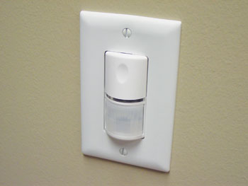
Photo 1. Switch locations will generally require a grounded conductor for such devices as occupancy sensors.
A new subdivision will require a grounded conductor to be provided to switch locations that control lighting, unless the wiring is installed in a raceway or the physical construction of the building allows for relative ease of future addition of other conductors. There are electronic lighting control devices, such as occupancy sensors that require a standby current to maintain the ready state and detection capability of the device. This allows immediate switching of the load to the “on” condition. These devices require standby current when they are in the “off” state, i.e., when no current is flowing to the lighting load. In many, if not most, commercial installations, a grounded conductor is not typically provided in the switch box for switches controlling lighting loads. When these devices are added after the initial installation, the installer of these control devices typically employs the use of the equipment grounding conductor to maintain this standby current. This introduces circulating currents on the equipment grounding conductor and any non-current-carrying metal in contact with these EGCs.
ARTICLE 406 Receptacles, Cord Connectors, and Attachment Plugs (Caps)
New: 406.4(D)(4) Replacements – Arc-Fault Circuit Interrupters
This proposal would require AFCI protection in existing locations where a replacement receptacle is installed in a location where AFCI protection would be required in new installations. The existing requirement in 406.3(D)(2) requires GFCI-protected receptacles where replacements are installed at receptacle outlets that are required to be so protected elsewhere in the NEC. The benefits of AFCI protection have been well substantiated over the last few NEC code cycles. There is no practical reason to limit the level of safety provided by an AFCI to new homes only. This proposal will provide AFCI protection for older homes by requiring the gradual replacement of non-AFCI-protected receptacles with new AFCI-protected ones.
These same receptacle replacement requirements have been proposed for tamper-resistant receptacles at 406.4(D)(5) and for weather-resistant receptacles at 406.4(D)(6).
ARTICLE 406 Receptacles, Cord Connectors, and Attachment Plugs (Caps)
New: 406.12 Tamper-Resistant Receptacles for Dwelling Units
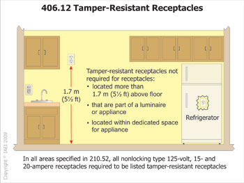
Figure 1. Exceptions proposed for tamper-resistant receptacle requirements
Three new exceptions were proposed to be added to the requirements for tamper-resistant receptacles in dwelling units. The requirement for tamper-resistant receptacles in all areas of a dwelling specified by 210.52 was added in the 2008 NEC process. This requirement applied to the majority of receptacles installed in dwelling units. Exception No.1 will exempt receptacles in areas specified in 210.52 that are installed more than 1.7 m (5½ ft) above the floor. Exception No. 2 would exempt receptacles in these areas that are part of a luminaire or appliance, and Exception No. 3 would exempt receptacles in areas specified in 210.52 that are behind a cord- and plug-connected appliance. Required spacing of receptacles in 210.52 must be installed at a height below 1.7 m (5½ ft.) to be considered as meeting the requirements for wall spacing. Receptacles installed above 1.7 m (5½ ft.) are not accessible and well out of reach of small children. Allowing the exception for a single receptacle or duplex receptacle located within dedicated space will eliminate the need for tamper-resistant receptacles to be installed behind dishwashers, refrigerators, washing machines and in other areas that are not typically accessible to children.
ARTICLE 410 Luminaires, Lampholders, and Lamps
New: 410.130(G) Special Provisions for Electric-Discharge Lighting Systems of 1000 Volts or Less – General – Disconnecting Means
Proposed change will require a disconnecting means to be added to existing florescent luminaires that do not have a disconnecting means when the ballast is replaced. A disconnecting means provides a safer working environment for the installer. It can be added with minimal extra effort at the time of replacement for an existing ballast, and it will provide a safer installation of the next ballast replacement. There are quite a few ballast disconnecting components available that can be easily installed during ballast replacement to meet this requirement.
ARTICLE 424 Fixed Electric Space-Heating Equipment
424.44(G) Installation of Cables in Concrete or Poured Masonry Floors – Ground-Fault Circuit-Interrupter Protection
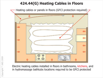
Figure 2. Kitchens were added to the areas requiring GFCI protection when electric heating cables are installed in concrete or masonry floors.
GFCI protection of electrical heating cables in kitchen floors will now be required in addition to bathrooms and hydromassage tub locations. For safety while one is washing dishes or mopping floors, GFCI protection of electrical heating cables in kitchen masonry floors should include the same GFCI protection currently provided in bathrooms and hydromassage tub locations.
ARTICLE 430 Motors, Motor Circuits, and Controllers
Revision: 430.24 Several Motors or a Motor(s) and Other Load(s)
This section for sizing of conductors supplying several motors or a motor(s) and other load(s) has been revised in its entirety to clarify the method of calculating motor-circuit conductors. The current language in NEC-2008 states that the conductors shall have an ampacity not less than 125 percent of the full-load current rating of the highest rated motor plus the sum of the full-load current ratings of all the other motors in the group, plus the ampacity required for the other loads. To some, this left questions as to what “ampacity required for the other loads” means. The new proposed language will clarify this uncertainty. These “other loads” are defined as 100 percent of the non-continuous non-motor loads and 125 percent of the continuous non-motor loads.
ARTICLE 430 Motors, Motor Circuits, and Controllers
Revision: 430.225(B)(1) Over 600 Volts, Nominal – Motor-Circuit Overcurrent Protection– Overload Protection – Type of Overload Device
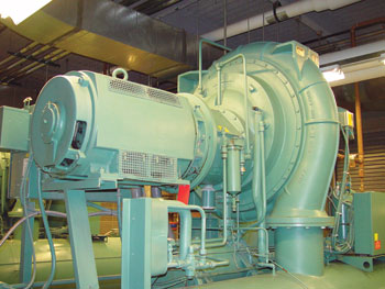
Photo 2. Engineering supervision will now be required to determine the sizing of overload and short-circuit protective devices for motors over 600 volts.
Engineering supervision will now be required to determine the sizing of overload and short-circuit protective devices for motors over 600 volts. Selecting the proper overload and short-circuit protection for medium voltage motor circuits is much more complicated than for low-voltage circuits. For medium-voltage motor circuits, it becomes very critical for the overload relay to coordinate with the short-circuit protection because some short-circuit protective devices cannot safely open below certain multiples of their rating. In these overload cases, the overload relay must open before the short-circuit protective device is asked to open. At the same time, the overload relay cannot safely open beyond certain multiples of its rating, requiring the short-circuit protective device to open. This all requires engineering supervision to lay out the curves of both the overload relay and the short-circuit protective device and to make sure that they are coordinated so that each opens only on levels of current for which it can safely open.
ARTICLE 445 Generators
New: 445.20 Ground-Fault Circuit-Interrupter Protection for Receptacles on 15 kW or Smaller, Portable Generators
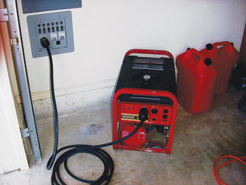
Photo 3. 15 kW or smaller portable generators are required to have GFCI protection for personnel, with the GFCI protection integral to the generator or receptacle.
This change will require all 125-volt, single-phase, 15- 20-, and 30-ampere receptacle outlets, that are a part of a 15 kW or smaller portable generator to have GFCI protection for personnel, with the GFCI protection integral to the generator or receptacle. Small portable generators, sized at 15 kW or smaller, are used for many different purposes, such as power on camping trips, on construction sites for temporary power, and for power during emergency situations for all different types of installations due to natural disasters. In all of these applications, there are many potential hazards associated with these temporary installations, such as cut and abraded wire and cable and standing water and wet locations. During power outages from storms and other natural disasters, persons who may not be familiar with adequate safety procedures often use these generators to supply power in less than optimal conditions. Requiring all 125-volt, single-phase, 15-, 20-, and 30-amperes on 15 kW or smaller generators to be integrally GFCI-protected will help eliminate the possibilities of shock hazards from damaged circuits, damaged equipment, or use of equipment in wet locations. This new proposed section will ensure that portable generators will have adequate personnel protection for these receptacles wherever these generators are used.
Chapter Five – Special Occupancies
Revision: 501.30(B) Grounding and Bonding, Class I, Divisions 1 and 2; 502.30(B) Grounding and Bonding, Class II, Divisions 1 and 2; 503.3(B) Grounding and Bonding, Class III, Divisions 1 and 2; 505.25(B) Class I, Zone 0, 1, and 2 Locations – Grounding and Bonding; 506.25(B) Zone 20, 21, and 22 Locations for Combustible Dusts or Ignitible Fibers/Flyings
Types of Equipment Grounding Conductors
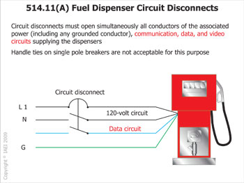
Figure 3. Isolated power systems conductors are to be identified with distinctive marking “along the entire length of the conductor.”
These five sections have been revised to clearly require an equipment bonding jumper for flexible metal conduit and liquidtight flexible metal conduit when used in these zones and divisions. Current language in these sections states that flexible metal conduit and liquidtight flexible metal conduit cannot be used as the sole ground-fault current path. The language goes on to state that if an equipment bonding jumper is installed, it shall comply with 250.102, Equipment Bonding Jumpers. The proposed language will leave no choice as to the installation of an equipment bonding jumper in conjunction with these flexible wiring methods.
ARTICLE 514 Motor Fuel Dispensing Facilities
Revision: 514.11(A) Circuit Disconnects – General
This revision will add associated power, communication, data, and video circuits (low voltage) to the simultaneous disconnection requirements of power circuits for motor fuel dispensing facilities. The current wording of 514.11 can lead to discrepancies in the way this section is applied to the design, installation and the inspection of motor fuel dispensing equipment. In many cases, the emergency stop disconnecting power to the dispenser is sometimes considered to be acceptable in the disconnection of external voltage sources. Dispensing equipment is supplied by more than just one external voltage source such as 120-volt power circuits for dispenser operation plus low-voltage circuits for data and communication equipment. While an emergency control may be an acceptable means for disconnecting the nominal power source from dispensing equipment, the emergency controls currently do not disconnect the low-voltage data/communication circuits. When not properly disconnected, the data/communication circuits have the potential to create an explosion and an electrical shock hazard. Adding data, communication, and video circuits to this section becomes even more important due to the increased number of circuits being connected to the motor fuel dispensing equipment. Today’s advanced dispensing equipment often requires additional circuits to add features such as “marketing at the pump.” This feature uses closed caption video feeds, advanced networking and display options. Other circuits can include such things as intercom, serial data, and current loop circuits.
ARTICLE 517 Health Care Facilities
Revision: 517.2 Definitions – Patient Bed Location
This change will no longer allow a small area of a room or space to be designated as a “critical care area” as the entire room will have to be considered to be subject to rules for this care level. Patient care is given in specific rooms within a health care facility. The term area can be misleading to the electrical installers and inspector. Using the term room is more easily defined. NFPA 99, Standard for HealthCare Facilities, uses this proposed definition to distinguish the location of various performance requirements for the health care facility. As such, the definition is a necessary part of NFPA 99, and should be common between the NEC and NFPA 99.
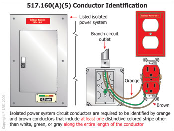
Figure 4. Isolated power systems conductors are to be identified with distinctive marking “along the entire length of the conductor.”
Revision: 517.160(A)(5) Isolated Power Systems – Installations – Conductor Identification
This proposal will require the conductor insulation for isolated power systems to be identified with distinctive marking “along the entire length of the conductor.” The previous language called for a distinctive coloring on the conductor, but not along its entire length. The requirement for a distinctive stripe is unclear as to the physical characteristics of the stripe. As currently written, a distinctive stripe can be applied to the conductor using vinyl marking tape or other means. This change clarifies that a wrap of marking tape or other marking made at the time of installation with colored tape is not acceptable to meet this requirement.
ARTICLE 547 Agricultural Buildings
Deletion: 547.5(G) Wiring Methods – Receptacles
All 125-volt, single-phase, 15- and 20-ampere general-purpose receptacles installed in agricultural buildings in areas having an equipotential plane, outdoors, damp and wet locations, and dirt confinement areas for livestock are required to have ground-fault circuit-interrupter protection. Previous language that relaxed GFCI protection for an accessible receptacle supplying a dedicated load where a GFCI-protected receptacle is located within 900 mm (3 ft) of the non-GFCI-protected receptacle has been proposed to be deleted. This allowance, which was added to NEC-2008 seems counter-intuitive to other areas of the NEC where GFCI protection is called for, such as 210.8. Equipment that is functioning correctly should operate without issues on a GFCI-protected outlet. A GFCI doesn’t open until a circuit has a leakage current of 4–6 mA, and, considering that listed equipment should have no more than 0.5 mA of leakage current, this allowance seems unnecessary.
ARTICLE 550 Mobile Homes, Manufactured Homes, and Mobile Home Parks
Revision: 550.25(B) Arc-Fault Circuit-Interrupter Protection – Mobile Homes and Manufactured Homes
AFCI protection for mobile homes and manufactured homes has been revised to coincide with other residential areas listed in 210.12(A). AFCI protection was expanded to more areas of the dwelling unit other than the bedroom in NEC-2008—areas such as family rooms, dining rooms, living rooms, parlors, libraries, dens, sunrooms, recreation rooms, closets, hallways. These same areas are proposed for AFCI expansion in mobile homes and manufactured homes as well. From 1999–2002, the fire death rate is roughly twice as high in manufactured homes as in other one- and two-family dwellings, and electrical distribution equipment continues to be one of the leading causes of manufactured home fires. By making the requirements for mobile and manufactured homes consistent with the requirements for other dwelling units, additional electrical wiring system fires can be diminished.
Chapter Six – Special Equipment
ARTICLE 600 Electric Signs and Outline Lighting
Revision: 600.5(B)(2) Branch Circuits – Rating – All Other Signs

Photo 4. LED type signs are limited to a maximum branch-circuit rating of 20 amperes.
In NEC-2008 there are no provisions for limiting the maximum size branch circuit for new sign technologies such as a light emitting diode (LED) type sign. This change will set this value at a maximum of 20 amperes. The previous language at 600.5(B) only addressed incandescent, fluorescent, and neon type signs. The new proposed language will address neon, with a maximum branch-circuit rating of 30 amperes and “all other signs” at a maximum rating of 20 amperes.
ARTICLE 625 Electric Vehicle Charging System
New: 625.2 Definitions – Plug-in Hybrid Electric Vehicle (PHEV)

Photo 5. Plug-in hybrid electric vehicles (PHEV) are considered electric vehicles.
A new definition was added to Article 625 for a plug-in hybrid electric vehicle (PHEV): “a hybrid vehicle intended for on-road use with the ability to store and use off-vehicle electrical energy in the rechargeable energy storage system.” The PHEV also has a second source of motive power. PHEV type vehicles are a relatively new type of vehicle with many similarities to electric vehicles with respect to their connection to a supply of electricity for vehicle charging. This particular proposal identifies plug-in hybrid electric vehicle supply equipment as an alternative and equivalent type of supply equipment and recognizes PHEV as an electric vehicle.
ARTICLE 680 Swimming Pools, Fountains, and Similar Installations
Revision: 680.22(B) Permanently Installed Pools – Area Lighting, Receptacles, and Equipment – GFCI Protection
This revision will clarify that all 15- or 20-amperes, 120-volt through 240-volt, single-phase outlets that supply pool pumps are to be GFCI-protected (cord-and-plug and hard-wired). Wording in NEC-2008 does not require GFCI protection for such things as 208-volt motors. Only two selected voltages (125-volt and 240-volt) require GFCI protection as currently written. In addition, this proposal recommends changing 125-volt to 120-volt. 125-volt may not be applicable in all instances. As an example, if a 120-volt pool pump motor is direct wired, the “outlet” is not rated 125-volt. The 125-volt rating is applicable to a receptacle, but not to a generic reference to an “outlet.” This appears to be an inadvertent oversight in NEC-2008 development process.
Revision: 680.26(B)(1)(b)(1) and (2) Permanently Installed Pools – Equipotential Bonding – Bonded Parts – Conductive Pool Shells – Copper Conductor Grid
This revision will clarify how connections are to be made for the bonding conductors being bonded to each other “at all points of crossing” for a copper conductor grid system. An equipotential bonding grid has to be established for a conductive pool shell at a permanently installed pool. Two methods are acceptable to establish this equipotential bonding grid: (a) structural reinforcing steel, and (b) a copper conductor grid system. Where structural reinforcing steel is encapsulated in a nonconductive compound or is not available, a copper conductor grid shall be installed. Present language provides no method for bonding conductors being bonded to each other “at all points of crossing.” There is no detail as to how the connections are to be made by the installer and as well as being acceptable for the authority having jurisdiction. This change would provide a method for connections and detail what type of identified devices are acceptable for maintaining the continuity of the system. The proposed language would require bonding of these bonding conductors in accordance with 250.8, Connection of Grounding and Bonding Equipment, or other approved means.
Further revision to this section addressed the copper conductor grid system having to conform to the contour of the pool and the pool deck. The proposed revised language would remove the requirement for the copper conductor grid to conform to the contour of the pool deck. This requirement for the pool deck (perimeter surface) seems to conflict with the requirements for the perimeter surface described at 680.26(B)(2). Perimeter surfaces are required to extend for 1 m (3 ft) horizontally beyond the inside walls of the pool, not to the contour of the pool deck.
New: ARTICLE 694 Small Wind Electric Systems
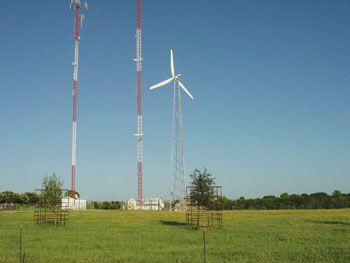
Photo 6. Small wind electric system
Hundreds of small wind turbines are being installed in the USA every month and there is no specific article to address the particular characteristics of their electrical systems. While many installations are stand-alone applications, most are utility interactive, and so requirements similar to Article 690, Photovoltaic Systems, should apply. Small wind electric systems are also being installed at rural, and now increasingly, in urban locations. The electrical safety of these installations can be improved by clear requirements for grounding and other aspects of the electrical installation. As wind turbine towers are typically tall structures, they are subject to lightning strikes and as such deserve special attention when connected to a premises electrical system. The proposed text follows the structure and, in many cases, the language of Articles 690, Solar Photovoltaic Systems, and Article 692, Fuel Cell Systems. This new article is a welcome and needed addition to NEC-2011 for installers and inspectors of small wind electric systems.
ARTICLE 695 Fire Pumps
New: 695.6(A)(3) Power Wiring – Supply Conductors – Multi-Building Campus Style Complexes
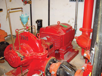
Photo 7. Fire pump covered by Article 695
This new requirement will generally require fire pumps for multi-building campus style complexes to be physically routed outside a building(s). This action was part of a larger proposal to rearrange the material in 695.6(A) and (B) to make it clear to the user how the rules should be applied. The present text mixes rules for service conductors with feeder rules and then has “other conductors” in item (B). This creates confusion because the exception in (A) deals with feeders only (because it applies on the load side of the automatic connection), but is located in a manner that is being interpreted by many to apply to service conductors. The proposed new language puts campus distribution provisions into its own section and gives it a title. A new sentence has been added to allow routing through the building in accordance with 230.6(1) or (2) to parallel the provision for services if the feeder conductors cannot be physically routed outside the building.
Revision: 695.6(E) through (J) Fire Pumps – Power WiringThe revision provides correlation and proper extract attribution between Article 695 and the recommendation for Chapter 9 in the 2010 edition of NFPA 20, Standard for the Installation of Stationary Pumps for Fire Protection. The new text is essentially verbatim from NFPA 20, Sections 9.3.6, 9.3.7 and 9.3.8. These proposed installation requirements are needed to supplement those already in Article 695.
Chapter Seven – Special Conditions
ARTICLE 760 Fire AlarmSystems
Deletion: 760.41(B) Non-Power-Limited Fire Alarm (NPLFA) Circuits – NPLFA Circuit Power Source Requirements – Branch Circuits
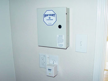
Photo 8. The requirements that NPLFA and PLFA fire alarm panels are not be fed from AFCI- or GFCI-protected circuits has been deleted.
Deletion: 760.121(B) Power-Limited Fire Alarm (PLFA) Circuits – Power Sources for PLFA Circuits – Branch Circuits
The requirements that non-power-limited (NPLFA) and power-limited (PLFA) fire alarm panels not be fed from AFCI- or GFCI-protected circuits has been deleted. The substantiation used in the past to justify this requirement was that de-energizing the fire alarm control panel (FACP) would result in the system ceasing to function with no indication of a loss of power, or that nuisance tripping would be an issue. However, the building occupants will be aware of the loss of power if the fire alarm is installed in accordance with NFPA 72, the National Fire Alarm Code. Section 4.4.1.5.3 of NFPA 72 requires that fire alarm systems be provided with a minimum of 24 hours of standby power, with enough power available at the end of the 24-hour period for the system to go into full alarm for 5 minutes (15 minutes of maximum connected load for emergency voice communications systems). Section 4.4.7.3.1 of NFPA 72 requires that failure of either the primary or secondary power supplies is to be annunciated with a trouble signal in accordance with Section 4.4.3.5, that requires the trouble condition to be annunciated within 200 seconds at a location where it is likely to be heard.
Another substantiation used in past revision cycles was that often times the secondary power supply of batteries are not provided, are missing, or are dead. Again, loss of the secondary power supply is required to be annunciated with a trouble signal within 200 seconds of the condition occurring. Furthermore, Chapter 10 of NFPA 72 details specific inspection and testing procedures that are to be performed at required intervals. A visual inspection of the primary and secondary power supplies is required to be performed at the time of initial acceptance or during any reacceptance of the system. Batteries, depending on the type, are required to be visually inspected at either monthly or semiannual intervals depending on the type used. The primary and secondary power supplies are required to be tested at regular intervals as well, with Table 10.4.2.2 detailing how those tests are to be performed. For a system to be up and running, the batteries would have to be in place and operating correctly.
There seems to be no justification for the exclusion of AFCI or GFCI protection in conjunction with these fire alarm systems. No substantiation has been provided to indicate that non-power-limited (NPLFA) and power-limited (PLFA) fire alarm systems are incompatible with AFCI or GFCI technology.
Chapter Eight – Communications Systems
New: ARTICLE 840 Premises-Powered Broadband Communications SystemsBroadband services are being offered that are non-network powered. At present, no specific article of the NEC addresses all the applications involved in these types of services resulting in state regulatory agencies, authorities having jurisdiction, and even companies making judgments on installations with loose interpretation or in some limited cases no interpretations of the NEC at all. Installations of these type systems have been found to create fire hazards and the potential for shock. This proposed Article 840 is an attempt to address these installation issues with these unique communication systems.
Summary
In this article and the previous article pertaining to Part I of the proposed changes to the 2011 NEC, the objective was to give the reader a first-hand look at some of the proposed changes to the next edition of the NEC. These articles include revisions, deletions, and new requirements as well as a look at some new proposed articles for NEC-2011. The information provided in this article is based on proposed changes and the code-making panel actions to the proposals at the Report on Proposals (ROP) stage of the NEC development process. The revisions and information in this article could be affected by public comments to the proposed changes. IAEI encourages public comments on the proposals. The NEC is a work in progress, and continues to evolve with new materials and growing technology in the electrical industry. These changes and many more will be fully explored in IAEI’s Analysis of Changes, NEC-2011 textbook. Look for this authoritative textbook to be available from IAEI about September–October of 2010.