
Load calculations in the National Electrical Code have evolved over many decades. It was in the 1933 NEC that load calculation requirements began to resemble a format that the modern code user would find familiar. Since then, many things have changed, but the primary requirement remains the same — service equipment and conductors must be sized to handle the expected load.
Article 220 of the National Electrical Code lays out the primary requirements for performing load calculations that are necessary for determining the size of a residential service. The calculations are based on the expected loads present in a dwelling unit, along with appropriate demand factors that are used to account for the diversity of electrical use by occupants. There are two methods available, standard and optional calculations. Optional calculations require fewer steps and generally result in smaller conductors, but the dwelling unit must meet more restrictive requirements. We will only be considering one-family dwelling units in this article, including single family residences, apartments, etc.
Be aware that some authorities having jurisdiction adopt the International Residential Code for One- and Two-Family Dwellings (IRC) and use the method for calculating the service size using the requirements found in Chapter 36. The IRC calculations are based on the National Electrical Code, but are not identical. Always check with your local jurisdiction to find out what method(s) are acceptable.

Photo 1. Electric range
Standard Method
The standard method for calculating service sizing is found in Part III of Article 220. Of course, we can’t find all the requirements in this Part, so we will also be looking at additional requirements in Articles 210, 220, 230, 250 and 310. An example load calculation using the standard method is shown in Table 1.
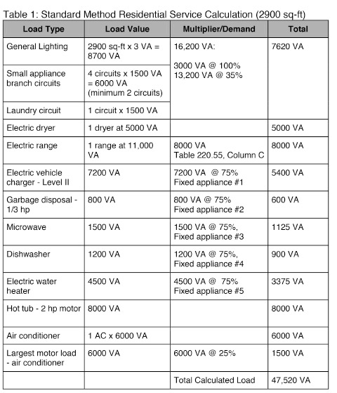
Table 1
Lighting Load
The first thing we need to determine is the lighting load. Table 220.12 requires that for dwelling units, we multiply the floor area (based on the outside dimensions of the dwelling unit) times 3 volt-amperes/square foot. Section 220.14(J) states that the following loads are also included in the general lighting load calculations:
- all general-use receptacle of 20-ampere rating or less, including the receptacles connected to the bathroom branch circuit required in 210.11(C)(3),
- the outdoor outlets in 210.52(E),
- the receptacle outlets in basements, garages, and accessory buildings in 210.52(G), and
- the lighting outlets required in 210.70(A), which includes habitable rooms, a variety of additional locations, and storage or equipment spaces.
Table 220.42 gives us demand factors for lighting loads. Most homes will take the first 3000 VA at 100% and the remainder at 35%. (If you are calculating a multifamily dwelling service, you might use the third demand factor category, where anything over 120,000 VA is taken at 25%.)
Small Appliance and Laundry Loads
Section 210.11(C)(1) requires a minimum of two small appliance branch circuits. Section 220.52(A) tells us that we must use a minimum load of 1500 VA for each of these circuits, but also allows the small appliance branch circuits to be included with the general lighting load when applying the demand factors in Table 220.12. Section 220.52(B) requires that 1500 VA be added for the required laundry circuit in 210.11(C)(2). This circuit can also be added to the general lighting load and demand factors may be applied.
Photo 2. Washer/dryer
Electric Dryers and Cooking Appliances
Section 220.14(B) refers us to requirements for electric dryers in 220.54 and electric cooking appliances in 220.55. Electric clothes dryers are calculated at either the minimum of 5000 watts or the nameplate rating, whichever is larger. The demand factors in Table 220.54 may be helpful if there are more than four dryers, but this is unlikely in a one-family dwelling unit, so we will not use this table for the examples in this article. Electric ranges and other electric cooking appliances (rated in excess of 1.75 kW) shall be permitted to be calculated in accordance with Table 220.55, which takes up an entire page and has five notes. There are also informational notes directing the code user to Annex D for examples. It is worthwhile to review this table and read all the notes and examples to become familiar with the various options.
Fixed-appliance load
If there are four or more fixed appliances in the residence, 220.53 permits all of these loads to be totaled and then a demand factor of 75% applied. Fixed-appliance loads include items such as a water heater, garbage disposal, dishwasher, microwave, etc.
Photo 3. Garbage disposal
Largest motor load
Section 220.14(C) tells us that motor loads shall be calculated in accordance with the requirements in 430.22, 430.24 and 440.6. For the service calculation, this means that we must determine the largest motor load and add 25% of its value to the total calculation. Common motor loads in residential applications include air conditioning, water pumps, disposals, blowers, etc. Often, the largest motor load in a home is the air conditioner. Even if the air conditioning is dropped from the total load calculation in favor of electric heating (see below), you may still be required to use the AC motor load for this calculation. Check with your jurisdiction to see what the policy is locally. Many jurisdictions publish residential load calculation worksheets to help with determining the size of the service.
Noncoincident loads
When two loads are not likely to be energized at the same time, 220.60 allows us to use only the largest load for the calculation of the service. This is typically applied to dwelling units with both electric heating and air conditioning, since they are not expected to run at the same time.
Specific appliances or loads
There are certain loads that may be found in residences that are not included in the previous list. Section 220.14(A) requires that an outlet for a specific load or appliance not covered elsewhere must be calculated based on the ampere rating of the load served. Some examples might include a spa, RV hookup, etc. These must be included in the load calculation at their full value.
Optional Method
The optional method is much simpler than the standard calculation, but is restricted in 220.82 to “… a dwelling unit having the total connected load served by a single 120/240-volt or 208Y/120-volt set of 3-wire service or feeder conductors with an ampacity of 100 or greater.” Most one-family dwelling units meet this requirement, so the optional method is used frequently. An example calculation using the optional method is shown in Table 2.
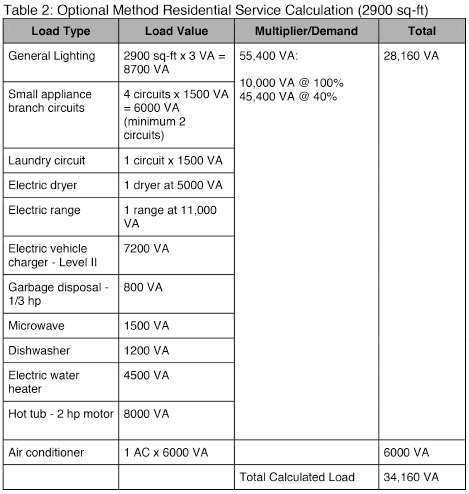
Table 2
General Loads
For the purposes of the optional method, everything except heating and air conditioning is considered to be a general load. For this method, the general calculated load shall be not less than 100 percent of the first 10 kVA plus 40 percent of the remainder of all loads other than heating and air conditioning.
Lighting and general-use receptacles are again based on the outside dimensions of the dwelling unit multiplied by 3 volt-amperes/square foot. The small-appliance branch circuits and laundry branch circuit are each included at 1500 VA.
The next step is to determine the nameplate rating of each of the following items:
- all appliances fastened in place, permanently connected, or located to be on a specific circuit
- ranges, wall-mounted ovens, counter-mounted cooking units
- clothes dryers that are not connected to the laundry branch circuit
- water heaters
For all permanently connected motors not included in the previous list, the nameplate or kVA rating must be included in the calculation.
Heating and Air Conditioning
The largest heating and air-conditioning load must be chosen from six options:
- 100 percent of the nameplate rating of the air conditioning and cooling
- 100 percent of the nameplate rating of the heat pump when it is used with no supplemental electric heating
- 100 percent of the nameplate rating of the heat pump compressor and 65 percent of the supplemental electric heating for central electric space-heating systems (If the heat pump compressor is prevented from operating at the same time as the supplementary heat, it does not need to be added to the supplementary heat for the total central space heating load.)
- 65 percent of the nameplate rating(s) of electric space heating if less than four separately controlled units
- 40 percent of the nameplate ratings of electric space heating if four or more separately controlled units
- 100 percent of the nameplate ratings of electric thermal storage and other heating systems where the usual load is expected to be continuous at the full nameplate value.
Comparing Standard and Optional Calculations
To see how the two methods compare, let’s take a look at a 2900 square foot residence with the following loads:
- lighting load
- 4 small appliance branch circuits
- laundry circuit 1500 W
- natural gas heating
- air conditioner 6000 VA
- electric range 11,000 W
- hot tub 8000 W (2 hp motor)
- Level II electric vehicle charger 7200 W
- electric dryer 5000 W
- garbage disposal 800 W
- microwave 1500 W
- dishwasher 1200 W
- electric water heater 4500 W
The standard calculation method is shown in Table 1 and the optional calculation method is shown in Table 2. Using the standard calculation, our total load is 47,520 VA. Dividing that by 240 volts gives us 198 amps. Using the next standard service rating requires that we use a 200-amp service. Since we have a 120/240-volt single-phase dwelling service, we are allowed to use NEC Table 310.15(B)(7) and use either 2/0 AWG copper or 4/0 AWG aluminum service conductors.
Using the optional calculation, our total calculated load is 34,160 VA. Dividing that by 240 volts gives us 142 amps. Using the next standard service rating requires that we use a 150-amp service. Once again, we are allowed to use NEC Table 310.15(B)(7), which requires either 1 AWG copper or 2/0 AWG aluminum conductors.
For this example, it is clear that the optional calculation permits a smaller service. From a practical perspective, due to equipment availability, it is likely that a 200-amp service will be installed rather than a 150-amp service.
Neutral Load
Neutrals are permitted to be smaller than the phase conductors in most residential service installations. Section 220.61 requires that the neutral load be determined by calculating the maximum unbalanced load between the neutral and any one ungrounded conductor. The values used for calculating the neutral size when using the standard or optional methods will often be different, as shown in Tables 3 and 4.
Section 230.42 states that the grounded conductor for a service shall not be smaller than the minimum size as determined in accordance with 250.24(C). If we have a single raceway (as is most common for service conductors), 250.24(C)(1) tells us that the conductor cannot be smaller than specified in NEC Table 250.66, but is not required to be larger than the ungrounded conductors.
For our standard service calculation, our minimum ungrounded conductor size was a 2/0 AWG copper or a 4/0 AWG aluminum. Using NEC Table 250.66 would require a neutral no smaller than a 4 AWG copper or a 2 AWG aluminum. In Table 3, we found that our calculated neutral load is 28,035 VA. Dividing that by 240 volts gives us 117 amps, which will require either a 2 AWG copper or 1/0 AWG aluminum from Table 310.15(B)(7). These sizes are larger than the required minimum, so we choose one of these conductors.
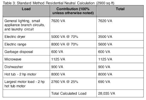
Table 3
For our optional service calculation, our minimum ungrounded conductor size was a 1 AWG kcmil copper or 2/0 AWG aluminum. Using NECTable 250.66 would require a neutral no smaller than 6 AWG copper or a 4 AWG aluminum. In Table 4, we found that our calculated neutral load is 30,320 VA. Dividing that by 240 volts gives us 126 amps, which will require either a 1 AWG copper or 2/0 AWG aluminum from NEC Table 310.15(B)(7). Since these sizes are larger than the required minimum, we would choose one of these conductor sizes.
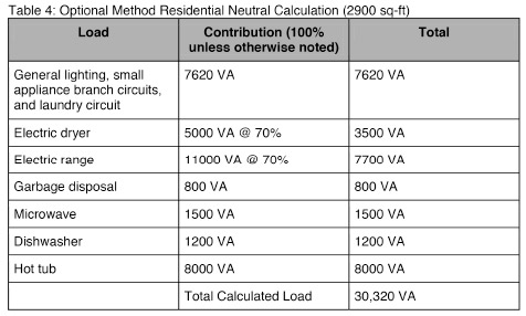
Table 4
Note that for this example in our optional method calculation, the neutral conductor is the same size as our phase conductors. However, if a 200-amp service is installed based on the standard calculation, the neutral is significantly smaller due to the calculation method. Table 5 shows a summary of the ungrounded and neutral conductor sizes for our example using both the standard and optional calculation methods.

Table 5
Conclusion
To accurately calculate the service size for residential installations, the designer and installer must be familiar with many requirements in the National Electrical Code. The requirements are not necessarily straightforward, and it is recommended that additional resources be reviewed. Available resources include the examples in Informative Annex D of the NEC, the IAEI publication One- & Two-Family Dwelling Electrical Systems, and other published examples.
Sidebar
310.15(B)(7) – Changes for the 2014 NEC
For most residential services, the service conductors and main power feeders are allowed to be sized based on Table 310.15(B)(7) instead of Table 310.15(B)(16), which permits a smaller size conductor to be used in many cases. This allowance has been in the NEC since the 1950s in recognition of the fact that only a small portion of the electrical loads in homes are typically used at the same time, so the load on the service conductors at any one time is generally much
smaller than the total calculated load.
The language in Section 310.15(B)(7) and the associated table have been a subject of great debate in code-making panel 6 (CMP-6) over the last few cycles. CMP-6 has
considered each of the proposals and comments received over the last few years
and come up with new wording to address the concerns and suggestions submitted.
CMP-6 has agreed to delete the existing wording and table and replace them with the following language:
For one-family dwellings and the individual dwelling units of two-family and multifamily dwellings, service and feeder conductors supplied by a single phase, 120/240-volt system shall be permitted be sized in accordance with 310.15(B)(7)(a) through (d).
(a) For a service rated 100 through 400 amperes, the service conductors supplying the entire load associated with a one-family dwelling or the service conductors supplying the entire load associated with an individual dwelling
unit in a two-family or multifamily dwelling shall be permitted to have an
ampacity not less than 83% of the service rating.(b) For a feeder rated 100 through 400 amperes, the feeder conductors supplying the entire load associated with a one-family dwelling or the feeder conductors supplying the entire load associated with an individual dwelling unit in a two-family or multifamily dwelling shall be permitted to have an ampacity not less than 83% of the feeder rating.
(c) In no case shall a feeder for an individual dwelling unit be required to have an ampacity greater than that of its 310.15(B)(7)(a) or (b) conductors.
(d) Grounded conductors shall be permitted to be sized smaller than the ungrounded conductors provided the requirements of 220.61 and 230.42 for service conductors or the requirements of 215.2 and 220.61 for feeder conductors are met.
Informational Note No. 1: It is possible that the conductor ampacity will require other correction or adjustment factors applicable to the conductor installation.
Informational Note No. 2: See example DXXX in Annex D.
In effect, the same size conductors that are allowed in the 2011 NEC will still be allowed in the 2014 NEC, assuming that temperature correction factors or adjustment factors are not required for the installation. The changes to the code language were necessary to take into account certain limitations inherent in the language in previous code cycles. Because Table 310.15(B)(7) is based on service or feeder ratings and not the temperature rating of conductors, there is no clear way to apply adjustment or correction factors for installations at higher temperatures or if there are more than three current-carrying conductors in a conduit.
It should be noted that the conductor sizing will still be based on the service or feeder rating, not the calculated load. For example, if you have a calculated load of 184 amps and are required to install a 200-amp service, the conductors would be required to have an ampacity of 166 amps or more:
200 amps times 83 percent equals 166 amps. So, for a 200-amp service, you would still be allowed to choose a 4/0 AWG aluminum or 2/0 AWG copper, but you would choose it from the 75 degree C column in Table 310.15(B)(16).