Well we’ve made it to chapter three of the National Electrical Code. I like to refer to this area of the code as the “nuts and bolts” of an electrical installation. Chapter 3 is entitled Wiring Methods and Materials, and it covers much of the mechanical portion of the code. This includes what materials we use, how to install them and where. For those preparing for a certification test, this is usually one of the key portions of the test for both open and closed book questions. In Article 300, almost every section is one you need to know to do both good quality installations or to perform thorough inspections of basic electrical systems. This article starts with some very basic items, but it is important that we cover these; so we are going to take our time and thoroughly go through several of the requirements in detail. In 300.1, we find General Requirements which include practices used throughout the code (unless specifically modified elsewhere) along with a short explanation that this article doesn’t apply to the integral parts of equipment, such as motor controllers or similar items. The last general item is Metric Designators and Trade Sizes, which includes a table of the sizes recognized in the NEC. Limitations are covered in 300.2, which includes voltage and temperature. Wiring methods in Chapter 3 shall be 600 volts unless specifically indicated otherwise. Temperature limitations of conductors will be covered in Article 310 where we get specific regarding conductors.
Continuing into 300.3 Conductors, in part (B) we find one of the basic rules regarding conductor arrangements. Basically, all the conductors of the same circuit and the equipment grounding conductor, if used, must be contained within the same raceway, gutter, cable tray or other items listed there. I know to some this will be a basic rule and you may ask why it even has to be mentioned in the code; however, it is a critical installation requirement. If installations don’t comply with this, some of the resulting problems may include poor power quality, harmonics and induction heating, which may lead to overheating of the conductors. Worse yet, if you are in a non-metallic raceway and damage occurs to one of the conductors and the equipment grounding conductor isn’t present, there may be no low impedance ground path allowing overcurrent protection devices to operate before further damage occurs to the system. This article continues into four subsections, which details some specific variations. The most common one to be familiar with is the paragraph that talks about Parallel Installations. These requirements are violated all too often, as you can see by some of the attached photos.
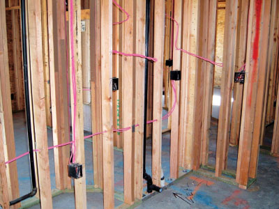
Photo 1
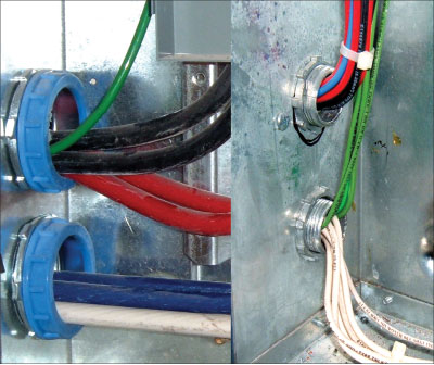
Photo 2. As mentioned in 300.3(B), conductors of the same circuit shall be in the same raceway. As simple as that sounds, you can see from these two photos that it is not always done. Two good code violations are shown here.
Conductors of Different Systems are covered in 300.3(C). This is a code section that is often missed by inspectors, especially ones who have not had a lot of commercial experience. In (C)(1) we find the conditions that must be followed for systems 600 volts or less; this is the one that causes most of the enforcement issues, as anything over 600 volts we generally have an eye out for since those systems are less common. When we deal with some of the new technologies that are out there for lighting control systems, we often find the controls are utilizing low-voltage signal wire or CAT 5 or 6 cable systems. The code requires that all the conductors within a cable, enclosure or raceway have a minimum rating of the maximum voltage applied to any one conductor within. So if we have a facility that is using a 480/277-volt system that is feeding the lighting system at 277 volts, then all conductors at the same location must be rated for a minimum of 277 volts.
Protection Against Physical Damage (300.4) is broken down into eight specific types of installations, and we will explore some of these in detail. So what are we worried about that could damage our systems? Nails, screws, and various other materials that may penetrate the finished wall after the building is occupied, or during a remodel or renovation. During any electrical inspection, this is the most time-consuming portion of the inspection process, as you must visually look at almost every foot of an installation, no matter what method is being used. So starting with part (A) Cables and Raceways through Wood Members, first we have Bored Holes. The rule here is that any bored holes must be 1¼″ from the nearest edge of the wood member. Why do we pick 1¼″ ? Well, most of the wall finish components, both interior and exterior, have attachment requirements which require about a ⅞″ penetration. So you can see we have a ⅜″ safety margin in an ideal world. Normal 2″ x 4″ wood framing members actually have only a 3 ½″ width for the electricians to work with, so let’s do a little math. If you take the required clearance from each side, which adds up to 2 ½″, that leaves an electrician 1″ for a bored hole. The bits commonly used range in diameter from ½″ to 1 ¼″. I used to have my employees use ¾″ bits to give a bit of a fudge factor in location.
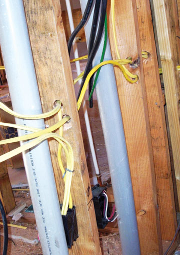
Photo 3. Here is an example of very poor stud boring locations, resulting in several conditions where we don’t have our 1-1/4″ clearance requirement.
The other issue with the boring bits is the length they come in; many electricians like to use bits that are 18″ in length, as it allows them to extend their reach. However, when you put an 18″ bit into a drill and add the length of the drill which is 6″ if using a right angle drill, you now have an assembly that is 2′ long. This won’t fit nicely between framing members, which are normally spaced 16″ or 24″ on center. This often results in angled holes being bored, many times creating a violation of the 1¼″ code requirement. So what do we do? The code goes on to say that if the 1¼″ requirement isn’t met, then you are to provide some other form of protection. This protection is accomplished by installing a steel plate that is a minimum of 1/16″ thick, which has to be the appropriate width and length to cover the area of wiring. There are two exceptions here, one that excludes rigid metal conduit, intermediate conduit, rigid non-metallic conduit and electric metallic tubing. It is felt that these methods are robust enough on their own to afford the needed protection; however, I have seen nail guns shoot nails right through rigid non-metallic conduit (PVC). The second exception is that you are allowed to use a listed and marked steel plate that is less than the required 1/16″ as long as it provides equal or better protection.
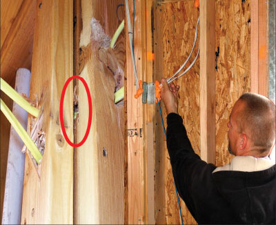
Photo 4. On the left, we have a case of angle drilling which has created an exposed area for the cable as outlined in the photo. On the right, we have the inspector checking a similar installation which has been properly protected.
One item I must mention here is that the framers often have a procedure they call “shim and shave.” This is their attempt to build nice straight walls. The issue here is that what may have been a bored hole that made the code requirements when made, may not be after they have shaved a ½″ off the face of a stud to straighten the wall. As a result of this, we would ask the builders not to call in for a rough inspection until after the shim and shave was done. Also, during this process, they often damage boxes, remove boxes or damage cable assemblies. So as you can see, it is best to do the inspection after all the trades are done and just before the wall coverings are installed. Personally, I used to use a 6″ long ¾″ bit and always paid careful attention to the location of my bored holes when I was in the field for two reasons: first, the finished job looked better; and second, the cost of the nail plates added up fast if you made a habit of missing.
The next paragraph deals with notches in wood and the protection needed if using notches. First, verify with the engineer that it is ok to notch the wood member, since notching can lead to a lack of structural strength. If notching is allowed, again we must protect the installation with a1/16″ plate as described above and with the same exceptions.
Continuing with protection in (B), we find Non-metallic Sheathed Cables and Electric Nonmetallic Tubing through Metal Framing Members. Here we must provide protection for these two types of wiring methods through steel studs. The first requirement is for nonmetallic-sheathed cable installations in steel studs. Steel studs come with factory punched holes through which we can pass this cable; however, at times these are not in the exact location we need, so we can also punch or cut our own holes. Either way, we must protect these wiring methods from the sharp edges of the steel studs. This is done by using listed grommets or bushings that cover all the metal edges through which we are passing; and, of course, they must be installed before the cable is pulled.
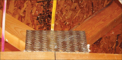
Photo 5. As mentioned in the article, you have to look at every foot of the installation to watch for areas where damage may occur or has occurred, as can be seen above. The cable installed over the gang nail has scraped the outer sheath off down to the actual conductors.
A personal story here: while I was inspecting tract homes being built by one of the largest builders in the country during the 1990s, they decided to change from wood framing to steel framing due to the rise in lumber cost. The electrical contractor had only done residential work and had never done steel framing. The result was a learning process which resulted in a slowdown of the project until they were able to improve their practices. In addition to just passing through the punched holes, the cable was also being damaged where it was pulled around corners of framing members where it didn’t actually pass through a stud, but got pulled tight against a perpendicular metal framing with very sharp edges. Since this increased inspection times to carefully inspect the installation, the contractor soon found ways of installing protective guards on the edges and then secured it with cable ties, keeping the cable in place to provide a good installation.
In 300.4(B)(2), we find similar language to that covered above regarding the penetration of nails or screws; again, we have to provide steel plates for protection.
Now we are going to skip to 300.4(D), which deals with installations parallel to framing members or furring strips. Furring strips are building materials that are not the usual dimensions of framing members. For example, if you are finishing off a concrete basement and want to add drywall to convert it into living space, it is common to install 2″ x 2″ furring strips to attach the drywall. In order to make a code-compliant electrical installation, we have to add receptacle and switches, so we notch the furring strips to pass through the cable. We must provide protection for the cable if it is within 1¼″ to the face of the furring strips. Often we will find the cable run in a piece of electric metallic tubing (EMT) to provide the protection required.
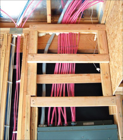
Photo 6. The above is an excellent installation providing proper protection of the cables, while not making numerous holes in the structural top plate of the wall. Also, please note the cable installed on the left where we have protection plates at the top plate and cable retention devices keeping the cables positioned the required distance from the face of the studs.
Moving on to 300.4(E), which was new to the 2008 and again modified in the 2011 code, we have requirements for Cables, Raceways or Boxes installed in or under corrugated roof decking. You will notice the unique language used here, “installed in or under,” leaving you no doubt that you aren’t allowed to have it within the upper channel of the decking. In fact, the wiring methods shall be at least 1½″ below the bottom corrugation. The main reason for this is that when the roofing underlayment is being installed, oftentimes the roofers use different thicknesses of material. In order to fasten the material in place, they have fasteners much like nails of different lengths. So as they work their way across a roof, they don’t always adjust the length of the fasteners, which means we get over-penetrations which could lead to damage to our electrical systems. If the electrical components are in the upper corrugation, you are almost certain to get damage.
In 300.4(G), I must mention a minor modification to Insulated Fittings: they must be identified for the use. These are the bushings and smooth rounded-edge fittings that provide protection for the conductors against damage to the insulation. Also in paragraph two, we have a simple note that an insulating material shall not be used to secure the fitting or raceway, meaning it is not to be used in place of a lock nut. I wouldn’t think that would need to be mentioned, but from time to time we would see this violation. Also, the temperature rating of the insulator shall match the temperature rating of the conductors.
The last portion of 300.4 we are going to cover is (H), which is Structural Joints. Structural joints are basically seams within building structures where we have a small separation or gap. As these two different parts are allowed to move separately for expansion and contraction, a rigid raceway system would pull apart or crush itself where it crosses the gap. Therefore, we need some form of flexible fitting that can absorb this movement. The code gives us two ways to do this, either by a listed expansion/deflection fitting or by an approved means, meaning something that is acceptable to the AHJ. Usually this is done by a piece of flexible raceway installed at the expansion joint with a little excessive length to allow for movement. If using a listed fitting, make sure it is listed for the raceway system you are using; don’t use a unit listed for rigid galvanized conduit only when you are using electrical metallic tubing.
Next we move to 300.5, Underground Installations.Our major concern with underground installations is the depth required to install the method we have chosen to use. These depths are listed in Table 300.5, but first we need to cover some basics. One is that all underground installations are considered to be wet locations. So make sure that the conductors are listed for wet locations, and recognize that this may limit you on the ampacity of some conductors. The reason for this is that no matter what part of the country we are in, at the very least we will have condensation within the raceways. Underground conduits commonly collect water — yes, even in the desert! Cables installed under buildings are to be in conduit unless they are MI cable or PVC jacketed MC cable.
In 300.5(D) and (E), Protection from Damage and Underground Splices are covered; please read these as they are well detailed. We will skip to (F), Backfill, as this is an item that frequently must be watched carefully. Often those doing the backfill are not the electricians, and they don’t show the proper respect to the systems we have installed. This is very hard for the inspector, as we inspect the system to make sure they have the required depth and the proper installation for the system used, but we don’t have time to stand by and watch the backfill process. You will have to work out a system that works for you. When gas lines for swimming pools were installed in the Las Vegas area, we made the contractor have sand on site in order for us to sign off the inspection. I’m not suggesting this for you, it is just an example and the system we used. If you are dealing with direct burial conductors or cables, the back fill is very important, as any sharp or abrasive material could damage the insulation or jacketing.
The last item before we review the table will be (J), Earth Movement. This is for those installations where we have direct burial systems that may be subject to movement due to settlement or frost. We must allow for this movement so that we don’t pull the conductors out of the termination points or pull the equipment off the wall. The movement is often compensated for by the installation of a slip-fit riser and a loop in the conductors to permit movement without damage to the equipment or conductors.
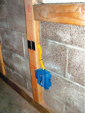
Photo 7. Here we have an example of a basement being finished out with 1-1/2″ deep furring members. Notice the protection of the cables through the wood members, but what about the protection of the vertical runs, which aren’t 1-1/4″ from the face of the framing members?
We will end this article with a review of Table 300.5. In all honesty, I have never tried to memorize this table, as there are too many details that apply to each installation. In the left column, we find the location of the wiring method. The one we use most often is under a building, under streets, etc., and one- and two-family dwelling locations. Across the top we have wiring methods and, in some applications, voltages applied to the wiring method. Using this matrix we can find the minimum depth required by code.
The first one I will mention is under a building in the left column; as you read across, you will notice that the depths are zero. Does that mean you can just lay the conduit on top of the sub-grade before concrete placement? In my opinion the answer is no, since the concrete slab to me was part of the building and the code says under the building, not in the building. Also, structural engineers get a little fussy when electricians start to put conduits in their structural elements. Basically, if you have a conduit within a slab, you have created a thin spot in the slab and a location for a crack or fracture of that slab. So we would ask to have these raceways installed such that the top of the raceway was level with the top of the sub-grade.
Next, if you are doing work under a street, road, alley, driveway or parking lot, no matter what, you need 24″. Typically, any installation around a dwelling unit is 18″ unless you have a 120-volt GFCI-protected circuit, then you only need 12″.
If you have followed along with the table for the examples I just gave, you get the gist of how to use the table properly. Please note there are five notes to this table which may allow for modifications to the table. Unlike information notes, these notes are enforceable. I will mention only one and that is Note 5, which talks about solid rock and getting a depth reduction due to this. In the desert, we often have a cementitious soil called caliche, which is basically as hard as concrete or solid rock. Fortunately, the trenching people have developed equipment which cuts through even this and we haven’t had to use this allowance very often in the last decade.
This brings us to a good stopping point for now. As you can see, Article 300 has very important information that we must have a good working knowledge of as both inspectors and electricians. Please remember to read the sections covered, as we have just skimmed the top of these in the interests of time and space. In the next article, we will continue with Article 300.