Standards versus Outline of Investigations
I can’t begin without addressing a fundamental aspect of UL Listed products that directly pertains to this AFCI discussion. We must first understand what a UL Outline of Investigation (OOI) is before proceeding. Most products you install are supported by a product standard which, in the case of AFCIs, is UL 1699 Standard for Safety ofArc-Fault Circuit Interrupters. A product standard like UL 1699 is an ANSI-approved document that is created through an ANSI process. The ANSI process requires a balanced panel of individuals assuring that no single interest group dominates. UL uses their Standards Technical Panel (STP) to usher this UL standard through the ANSI process. These STPs are similar to the code-making panels that you and I are most familiar with in the NFPA process. Both processes are ANSI-accredited. This balanced panel reviews proposed changes, votes, and ultimately produces an updated consensus standard. The other document I mentioned above, the OOI, is different in that it is not a document that has gone through the same ANSI process described for a UL standard. UL defines the OOI as “. . . a document that contains the construction, performance, and marking criteria used by UL to investigate a product when the product is not covered by the scope of an existing UL Standard for Safety. Outlines are not consensus documents and do not require review by an STP or other external group.” This definition is relevant as you will see later in this article. It is a way that a new product which has no UL standard can quickly come on the market and yet still be evaluated to a predefined test specification. From my experience, the OOI is usually a document that has received industry input from various organizations and just may be the first draft of a future UL /ANSI standard, but has not yet gone through the sometimes lengthy ANSI process.
UL standards contain performance basedtestingthat verifies products will do what the standard intends the products to do and confirms that the product safely performs these duties under the conditions in which it is intended to be applied. Let me explain performance based through an example of a performance based test and a prescriptive requirement. One AFCI test requires cutting into a wire with a sharp blade, causing an arc that must be cleared before a wrap of cotton ignites. This is an example of a performance based test and not a prescriptive requirement. A requirement that all AFCIs must have 30 mA ground fault would be an example of a prescriptive requirement, and one that is not in the standard. UL Standards thrive on performance based test requirements.
UL 1699 Standard and Associated OOIs Background
The origins of UL 1699 can be traced back as far as 1997. The draft requirements of this standard were used as input to the certification of branch-circuit AFCI devices available on the market at that time. Those first devices were initially UL Listed under the Standard for Molded-Case Circuit Breakers, UL 489, and UL Classified for mitigating the effects of arcing faults. UL subsequently pulled together an industry advisory group in the Fall 1998 to develop the draft requirements for the first edition of UL 1699 which was ultimately released in February 1999. The performance based test standard used in the classification of the first AFCIs on the market in 1997 may not have been called an OOI by UL at the time, as they are today, but it indeed resembled the process as we know it.
Today, UL utilizes Standards Technical Panels, (STPs) to usher standards through the ANSI consensus process. The ANSI consensus process has a strict set of guidelines that include important aspects of: Openness, Lack of Dominance, Balance and Consensus Voting.
Products that can be listed to UL 1699 standard requirements include the following:
- Branch Feeder AFCI (Category AVZQ)
- Combination AFCI (Category AWAH)
- Portable AFCI (Category AWDO)
- Cord AFCI (Category AWAY)
- Outlet Circuit AFCI (Category AWCG)
The outlet type AFCI above is not the Outlet Branch Circuit (OBC) AFCI that we have seen mentioned recently. We’ll discuss the differences later. The OBC AFCI is listed to an OOI, “Outline of Investigation for Outlet Branch Circuit Arc-Fault Circuit-Interrupters” and not to the ANSI /UL 1699 standard. The UL White Book discusses all of the above types of AFCI Categories; the OBC AFCI is found in Category AWBZ. Another type of AFCI that is listed to an OOI is the Photovoltaic DC AFCI, Category QIDC, listed to “Outline of Investigation for Photovoltaic (PV) DC Arc-Fault Circuit Protection.” This too can be found in the UL White Book but will not be a focus of this article.
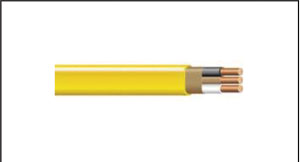
Figure 1. NMB Conductor used in UL 1699 testing.
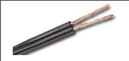
Figure 2. SPT-2 Conductor used in UL 1699 testing.
UL 1699 Arc-Fault Testing
If you were to purchase a copy of UL 1699 and look through the table of contents, the following are the performance tests conducted on AFCIs:
- Drop and Impact Tests
- Humidity condition
- Leakage Current Measurement
- Voltage Surge Tests
- Environmental Test
- Arc Detection Tests
- Unwanted Tripping Tests
- Operation Inhibition Tests
- Dielectric Voltage Withstand Tests
- Resistance to Environmental Nose Tests
- Normal Temperature Tests
- Operating Voltage Test
- Overload
- Endurance Test
- Abnormal Operation Test
- Surge current test
- Abnormal overvoltage test
- Short circuit current test
- Terminal lead strain-relief test
- Power-supply cord strain-relief test
- Mechanical tests
- Crushing tests
- Dust test
- Performance of markings
- Reverse line – load miswire test
- Supplemental voltage surge immunity test
As you can see, the performance testing for AFCIs is quite extensive. I will focus on arc detection tests, unwanted tripping tests, and operation inhibition tests. I will also discuss the requirements in the OOI for the OBC AFCI but will leave the PV AFCI for another day.
There are four arc detection tests described in UL 1699. These include the following:
- Carbonized path arc ignition test
- Carbonized path arc interruption test
- Carbonized path arc clearing time test
- Point contact arc test
Not every product listed to UL 1699 has to be tested to the above arc detection tests. Table 1 illustrates the arc detection tests that must be performed for each of the devices that can be listed to UL 1699.
You’ll note the references in the tests above to NM-B and SPT-2 conductors. Not every test is performed on both types of conductors but these are the only types of conductors that are used. They are depicted in figures 1 and 2 respectively. Tests conducted on NM-B are performance tests that verify the tested product can detect and mitigate the effects of arcing faults in the installed wiring of a home. Tests conducted on SPT-2 cords are performance tests that verify the tested product can detect and mitigate the effects of arcing faults in cords, like those connected to receptacles which are usually attached to appliances.
Now let’s take a look at these arc detection tests, one at a time.
1. Carbonized path arc ignition test (figure 3): This test is conducted on NM-B samples only. The outer jacket of the NM-B sample is removed, insulation is removed from one conductor, and this conductor is cut. This area is then covered with electrical tape and loosely wrapped with cotton. A test apparatus is used to create a carbonized arcing path that can be sustained at 120 volts at varying RMS load currents as low as 5 amps. The AFCI must interrupt the circuit before the cotton ignites. Many call this a “Series Test,” but I would much rather refer to this as a “low-current” arcing test since the current is restricted by the load, and is a minimum of 5 A.
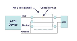
Figure 3. Carbonized Path Arc Ignition test sample preparation performed on the Branch Circuit and Combination Type AFCI. This one line diagram illustrates the preparation of the sample to be tested.
2. Carbonized path arc interruption test (figure 4): This test is conducted on both NM-B and SPT-2 samples. To prepare the sample, a cut is made to penetrate the insulation across all conductors. This area is then covered with electrical tape. A test apparatus is used to create a carbonized arcing path that can be sustained at 120 volts. This test is conducted without a connected load, at 100 A and 75 A as delivered by the source. The AFCI must clear the arcing fault if 8 half-cycles of arcing occur within a period of 0.5 seconds. Many refer to this as a “parallel test,” but I would much rather refer to this as a “high-current” arcing test since the current is not restricted by any load and is at a minimum, 75 amps.
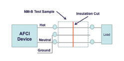
Figure 4. Carbonized Path Arc Interruption test sample preparation performed on the Branch Circuit and Combination Type AFCI. This one line illustrates the preparation of the sample to be tested..
3. Carbonized path arc clearing time test (figure 5): This is the sole additional arc detection test required for the combination-type AFCI, beyond that which is required for the branch/feeder type. It is conducted on SPT-2 samples only. The test sample ends are cut and separated. A cut is made to penetrate the insulation across the conductors, and this area is then covered with electrical tape. A test apparatus is used to create a carbonized arcing path that can be sustained at 120 V. As in the carbonized path arc ignition test above, which is only performed on NM-B, a load is used to adjust the RMS load current as low as 5 amps for this test. The AFCI must interrupt the circuit before the times specified in the standard (at 5 A = 1.0 seconds). As noted above, this test is commonly referred to as a “Series Test,” but I would rather refer to this as a “low-current” arcing test since the current is restricted by the load, and is a minimum of 5 A.
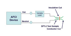
Figure 5. Carbonized path arc clearing time test sample preparation. This is the only extra test a combination type AFCI must pass. This one line illustrates the preparation of the sample to be tested.
4. Point contact arc test (figure 6): known as the “Guillotine Test,” here a utility knife blade is utilized to attach a hinged lever arm that is slowly closed onto a test sample such that the blade cuts through the wire insulation causing an arc. Many, at IAEI events saw this test as manufacturers would demonstrate it during meetings. The AFCI must trip if 8 half-cycles of arcing occur within a period of 0.5 seconds. The test is conducted without a connected load at several specified current levels between 500 A and 75 A, as delivered by the source. Both NM-B and SPT-2 samples must be tested. Many refer to this as a “parallel test,” but I would much rather refer to this as a “high-current” arcing test since the current is not restricted by any load and is at a minimum, 75 amps.
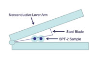
Figure 6. Point contact test sample preparation performed on the Branch Circuit and Combination Type AFCI. This diagram illustrates how the steel blade cuts the insulation and causes the arcs in this test.
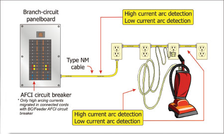
Figure 7. Illustrates the tests performed and protection provided by the branch feeder and combination type AFCIs as per the UL 1699 Standard. Note that a Branch Feeder AFCI mitigates from high and low arcing currents in installed NMB but only high arcing currents in connected cords. The Combination type AFCI extends the low current arc detection to connected cords.
Table 1 illustrates the fact that the difference between a branch feeder and combination-type AFCI is NOT that one does “parallel” arc detection and the other does “parallel” and “series” arc detection, but rather that the combination-type AFCI extends low-current arc detection to connected cords.
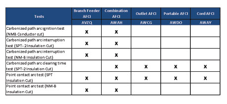
Table 1
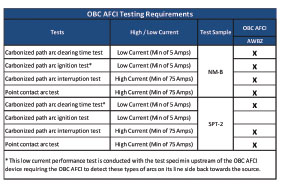
Table 2
The OBC AFCI
The outline of investigation for the OBC AFCI device, because it is intended to detect arcing and sparking, a basic function of a UL 1699 device, utilized the UL 1699 standard as the basis for its development, referencing it heavily and performing many of the same tests that the combination-type AFCI must perform. Table 2 illustrates the arc detection tests required to be performed by the OBC AFCI. As noted in this table, there is an additional twist to two of the tests listed that make the OBC AFCI unique. Other listed devices are only required to look downstream. A combination AFCI, UL category (AWAH) for example, in the loadcenter, must detect high and low current arcing in all connected downstream NM-B and SPT-2 conductors. It does not look back towards the utility or other branch circuits on the same bus and, in fact, has technology to ensure this does not occur. The outlet-type AFCI, UL category (AWBZ) again this is not the OBC AFCI, must detect high-current and low-current arcing in connected cords (SPT-2) and downstream NM-B conductors connected to its load terminals. This device does not have to detect arcing in the NM-B conductors connected to its line-side terminals, looking back towards the utility.
The OBC AFCI, on the other hand, must detect high-current and low-current arcing on connected cords (SPT-2) and downstream NM-B conductors connected to its load terminals as well as detect low-current arcing in the NM-B conductors connected to its line-side terminals. The line-side arc detection for this device does not include detecting high-current arcing. This additional test of low-current line-side arc detection is in essence looking back towards the source for low-current arcing. An arcing fault that trips an OBC AFCI circuit could be on the load side of the device, in a connected cord, in the downstream NM-B conductors connected to its load terminals or in the line-side NM-B conductors connected to the line terminals of the device anywhere upstream. Figure 8 illustrates the protection coverage of the OBC AFCI device.
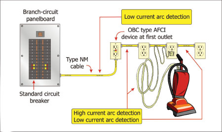
Figure 8. Illustrates the tests performed and protection provided by the OBC AFCI device as per the Outline of Investigation for this device.
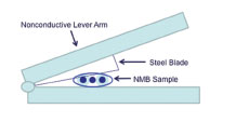
Figure 9. Point contact test sample preparation with NMB instead of SPT-2 cord as shown in Figure 6.
Unwanted Tripping Tests
In addition to arc detection, it is important that the AFCI device does not needlessly trip. The UL 1699 standard has a section of the document focused on taking a representative AFCI of each rating and ensuring that it does not trip after being tested under various loading conditions including inrush currents, normal operating arcing, non-sinusoidal waveforms, cross talk, multiple loads and even lamp burnout. Tests are performed with various types of appliances from a flat iron skillet to vacuum sweepers and air compressors. Not every manufacturer’s device or model types are tested in these standards.
This testing is quite extensive and, as noted above, includes using tools and appliances you would find in a home. But this is an area where manufacturers go above and beyond to ensure their products perform in the market without unwanted tripping. More than one model or manufacture of an appliance is tested, more combinations of loads, varying models from various brands. It is a fact that if you walk through the AFCI labs of any one AFCI manufacturer, you will find products with which tests are performed that are not in the UL 1699 standard. The answer to why a manufacturer would do this lies in the desire to be the best in the market, to reduce warranty claims, and to maintain customer loyalty to name a few. Each manufacturer strives to have a product that operates with any load on its circuit yet detects the dangerous arcs that may be the source for fires. Other examples of this can be found in efficiency type standards. There is a lot of evidence where manufacturers have gone above and beyond to be the best in their markets. Whether it is to boast better gas mileage than their competition, more efficient transformers or lamps, or even longer lasting batteries, the work that the manufacturer does to have the best product on the market can be viewed as a competitive advantage.
Operation Inhibition Tests
So far we have discussed performance based testing that ensures an AFCI detects arcs and unwanted tripping tests that ensure it detects the bad arc and not the good arcs causing a trip. However, we can’t forget the fact that an AFCI must detect dangerous arcs without being masked by other types of loads on the same circuit. These tests in the UL standard help to ensure dangerous arcs can be detected even in the presence of other loads that may act to mask the arc, preventing the AFCI from doing what it needs to do — open the circuit when an arc fault exists. Scenarios such as electromagnetic interference (EMI), masking loads such as vacuum sweepers, air compressors, switching power supplies, electronic lamp dimmers and more are tested with the AFCI device to ensure its robust arc detection methods operate correctly in these “dirty” environments. High-current and low-current arcs must still be detected when other loads are on the circuit.
Series versus Parallel
The terms series arcs and parallel arcs are used quite heavily in discussions pertaining to AFCIs to describe the types of arcs that are being detected and to describe the differences between types of AFCIs. While it would appear that using these terms helps simplify the complex, we know that from an electrical standpoint this is technically not a correct use of these terms and, depending upon what they are used to describe, may not describe the facts at all.
Let’s first look at the definition of the words “series” and “parallel.” Merriam-Websterdefines series as “a number of things or events of the same class coming one after another in spatial or temporal succession.” This resource defines parallel as “extending in the same direction, everywhere equidistant, and not meeting.” Both of these definitions utilize a relationship or a comparison between two or more objects as the basis for the definition. These two words, in our context, are intended to describe the relationship between two or more elements of an electrical circuit. These terms, when used by themselves, series arc or parallel arc do not identify which element(s) are in series/parallel with another. If you draw a circuit, the terms series and parallel will heavily depend upon how you draw your circuit and reference the components in the circuit. From a technical perspective, these words do not provide clarity.
These terms are also used when describing the difference between a branch-circuit AFCI and a combination-type AFCI. You’ll hear, “A branch-circuit AFCI detects parallel arcs and the combination-type AFCI detects parallel and series arcs.” Plain and simple, this is incorrect. The reason is due to the facts we discussed above. Look at the carbonized path arc ignition test, figure 3, that the branch-feeder and combination-type AFCI must pass. Ask yourself if that is what you envision when someone says series arc. Is that conductor cut and subsequent arc across that conductor cut in series with the load? In this test, the current is limited down to 5 amps by the load because it is performed for both the branch-feeder and the combination-type AFCI devices, saying that the branch-feeder does not detect series arc faults is not an accurate statement per the standard.
If instead of usingseries and parallel we use low-current and high-current, respectively, our explanation is technically accurate and should be understandable. A better way to describe the difference between a branch-feeder AFCI and a combination-type AFCI would be as follows:
“A branch-feeder AFCI offers high- and low-current arc detection for installed NM-B wire and high-current arc detection for connected cords. The combination-type AFCI offers the same level of protection afforded by the branch-feeder AFCI but extends the low-current arc detection to connected cords.”
AFCIs and Ground Fault
In the past, confusion around the definition of a combination-type AFCI left some thinking that the combination-type AFCI was a combination of AFCI and GFCI in the same device. The UL 1699 standard does not include a prescriptive requirement of any level of ground-fault protection. Some AFCI devices do indeed have a level of ground-fault protection which may vary from manufacturer to manufacturer. Ground fault added to an AFCI is there primarily as a means to pass the carbonized path arc ignition performance test included in UL 1699 and described above. (See figure 3). An AFCI device that carries an additional listing to either UL 943 or UL 1053 standards would be considered a dual purpose AFCI device which provides people protection or equipment protection respectively.
Closing Remarks
The arc-fault circuit interrupter is a device that is technical in nature, wrapped in controversy, fueled by passion, and delivers a positive electrical safety impact to the electrical industry. For examples of found electrical products, bookmark www.afcisafety.org and check it often as there is a document on that web site that provides examples of found electrical problems. Together we can make a difference.
As always, keep safety at the top of your list and ensure you and those around you live to see another day.