
How much do you know about Articles 408 and 409? From my experience, this question often results in a long pause, and then perhaps a couple of requirements from Article 408 get quoted. Up until 1999, this was Article 384; in the 2002 Code, it was moved to Chapter 4. Since the topic is not a wiring method as covered in Chapter 3, it fits better into Chapter 4, which is Equipment for General Use. This article is based on the 2011 NEC, and Article 408 contains requirements for Switchboards and Panelboards, which are installed on nearly every project we ever inspect. The first logical place to start is a review of exactly what a switchboard and a panelboard are, including similarities and differences.
Comparison of Switchboards and Panelboards
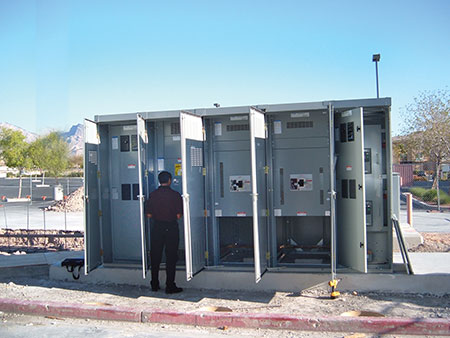
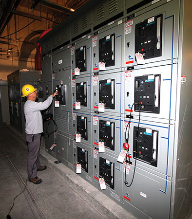
A switchboard is freestanding and usually provides front and rear access. It has a framework to which are mounted the bussing, overcurrent devices and instruments, and it is completed with covers over the live parts. It can be multiple sections joined together through horizontal bussing; it may house molded case circuit breakers, power circuit breakers, and fusible switches. Switchboards can be rated up to a 5000 amperes maximum main, and they are generally three-phase.
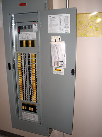
On the other hand, panelboards are assemblies that are installed within a cabinet or enclosure. They are flush or surface wall mounted with front access only. They consist of an enclosure, an interior section (bussing), a breaker section and trim, which is the cover or door. The overcurrent devices within the panelboards are miniature and molded case circuit breakers and/or fusible switches, but they can only go into a 1200 ampere main. These may be single-phase or three-phase.
So what do they have in common? They each serve as a distribution point for incoming power sources to be divided and fed to multiple circuits. They each house some form of overcurrent device and therefore must be readily accessible. They each have to be rated for the environment that we install them in; for example indoors, outdoors, or perhaps a hazardous location. They each have a short-circuit current rating, which we absolutely have to verify is greater than the available fault current that is present at the installation location. One word of caution with this type of equipment: these are built to UL Standards and are listed when they leave the factory. If something is changed within a switchboard or panelboard after it leaves the factory, and the change is not a field installable device listed by the company that makes the equipment, then the equipment has been modified from its original listing and would need approval of the AHJ or re-listing by a nationally recognized testing laboratory.
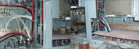
Section 408.3 has some basic requirements, and I will point out a couple of items of interest. The first is 408.3(A)(3), titled Same Vertical Section; here we find the requirement that conductors that are intended for termination in one section of multi-section switchboard shall not travel through another section before termination. There is, of course, an exception; however, these are seldom built with a horizontal chase that has barriers in place to create a wiring chase. The problem usually found in the field happens when conduits are run underground; the physical installation of conduits is generally laid out and installed before the switchboard is installed (and often before it is even onsite). Care must be used to make sure the conduit stub-ups are located properly to line up in the proper section of the switchboard assembly. I have seen cases where no forethought was given to the switchboard placement, and the installer simply took all the underground conduits and bunched them together because “This is where the gear goes.” As a good inspector, it is often useful to ask the contractor if they have the submittals for the gear and if they have checked the footprint drawings to make sure the conduits are aligned. This question might just be the reminder the contractor needs. It makes you a better inspector if you can be proactive at times.
Continuing with the general rules for both switchboards and panelboards, we have a requirement to prevent overheating and inductive effects. Usually, the buss bars are factory arranged, but conductor arrangements are done in the field. Make sure the circuits are grouped together; running phase A on one side of the panel and phase B and C on the other side would not be good for inductive reasons.
When using this equipment for service equipment, we need to make sure the provisions for a main bonding jumper as required by Article 250.28(D) are followed. All sections of a switchboard must be bonded together using an equipment bonding conductor sized per the appropriate code section (depending on if it is service equipment or not), using either Table 250.122 or Table 250.66.
Phase arrangement is covered next. To some this may be a very basic requirement, but if you ask most electricians where it is in the Code, you’ll get a blank look. In 408.3(E), the details for phase arrangement are covered; phases A, B, C shall be arranged from left to right and from front to back, depending on how the equipment is made. If this is not the arrangement you have, then you must clearly mark exactly what the arrangement is.
The next two items in 408.3(F) deal with markings related to the voltage system present. If you have a high-leg configuration or an ungrounded system, you are required to mark clearly the switchboard or panelboard with a field marking stating this. Please review your codebook for the exact language.
Either type of equipment must also comply with Article 312.6 to allow for the proper wire bending space. Care must be taken here when oversized conductors are installed to account for temperature correction, ampacity adjustment or voltage drop. Oversized conductors may require more bending space, which is often not taken into consideration during design or installation.
In 408.4, we find field identification requirements; simply put, we must have a circuit identification directory that (without any need for additional investigation or thought) will identify what is fed from that circuit. Also, the source or power to the equipment must be identified. This information is very important for service personnel, first responders, or others trying to work on the system. Of course, we have an exception for this on one- or two-family dwellings.
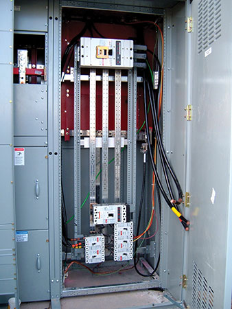
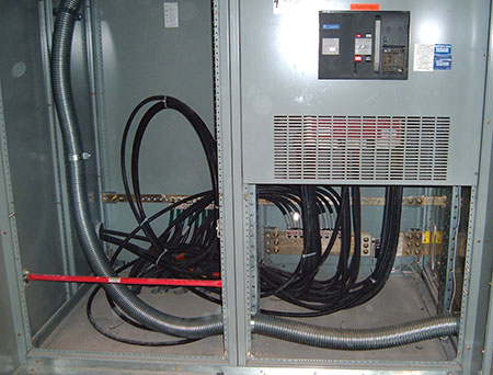
The next item to cover for inspections is 408.5 Clearance for Conductor Entering Buss Enclosures. Here we find two details that my inspectors have had to call, and the contractor is usually caught off guard when they hear these calls. The first item I will mention is at the end of the paragraph; a conduit, including end fittings, shall not rise more than 3” above the bottom of the enclosure. This is a tough item to fix if it is metallic conduit and the wire is already pulled. The other item is the clearance requirement for the locations the manufacturer shows as the approved location for conduit entries. These clearance requirements are found in Table 408.5 and vary depending on whether the bussing is insulated or bare. Usually, the manufacturer’s design has accounted for these clearances. However, if you find a conduit entry into the gear and the clearances between the conduit and the bussing look a little too close, it is likely that the conduit is higher than 3”, the bussing is too close to the bottom of the enclosure, or they have done a conduit entry in a location that isn’t approved for entry as per the manufacturer. We can’t simply enter the equipment for convenience where we may not provide minimum wire bending space to busbars.
Part II of Article 408 deals specifically with switchboards, and I will summarize the items found here. First, if the switchboard is installed in a wet or damp location, it shall meet the requirements of 312.2. Installation locations must be chosen to minimize the probability of having a fire to adjacent combustible material, and an open bottom switchboard shall not be installed over a combustible floor. If the enclosure is not totally enclosed, then a 3-foot clearance is needed between the top of the board to any combustible ceiling, unless protected. Clearances around the switchboard shall meet the base requirements of 110.26.
Part III covers specific items just for panelboards. We will review several of the items here that a good inspector should be aware of in order to do quality work. The first general item is that the panelboard shall have a rating equal to or greater than the calculated feeder load according to Article 220; also the overcurrent device protecting the panel shall not be greater than the rating of the panel. There are some exceptions to this as you can read in your codebook. Another thing to consider at this point of an inspection is making sure the fault current rating of the panel can handle the available fault current at that point of the system. Look for terms like AIC (amps interrupting capacity), AIR (amps interrupting rating), kAIC (“k” stands for thousands of amps interrupting capacity). All of these are referencing the amount of fault current the equipment can safely interrupt and care must be taken here to verify the values. All too often, in an effort to reduce the price of a project, lower rated equipment is purchased to save money.
If a panelboard is fed from a transformer, 408.36(B) clearly states that an overcurrent protective device must be on the secondary side of the transformer. This is generally done by either a separate fused disconnect or a main breaker within the panel. This needs to be verified, as every now and then someone will try to slip in a main lug only (“MLO”) panel and say it is protected by the overcurrent device on the primary of the transformer.
The next common item is an application using a back-fed device. This may be used to feed a panel without having to use an expensive main device that adds cost and makes the panel a larger size. A breaker that is approved for back feeding is installed on the bussing and connected to the feeder to provide power for the panel. When this is done, this breaker must be labeled as the “main breaker.” Additionally, the rule in 408.36(D) states that when we do this, the breaker must have an additional means to secure it to the panelboard. This is generally accomplished with a screw that secures the breaker to the breaker foot flange. We are seeing more back-fed breakers being used in photovoltaic installations where the photovoltaic system is connected to existing electrical systems.
As mentioned earlier, the panelboard shall be mounted within a cabinet or enclosure that includes some type of dead-front feature so that no exposed live parts can be contacted under normal operation.
If we use fuses within the equipment, they shall be installed on the load side of the switch feeding the fuse. This is a critical safety item. When the fuse needs to be serviced or replaced, it can be done safely by opening the switch and de-energizing the fuseholders.
Any metallic parts of a panelboard frame or cabinet shall be grounded as per 408.40; this shall be accomplished by physical connection of the parts and then connection to an equipment grounding conductor. Review this article for specifics and the exception related to isolated grounds. Again, as I have mentioned in previous articles, this grounding requirement is our safety path in the event we have a fault condition within a panel. This connection is what provides us a return path that allows adequate current to flow and open the device upstream to interrupt the fault current.
Grounded conductor terminations are covered in 408.41, and the key takeaway is that each grounded terminal (generally neutrals) shall be terminated in such as way that only one conductor is used for each termination point (no doubling up conductors). There is an exception for parallel conductors if the terminal or lug is identified for more than one conductor.
This brings us to Part IV of 408, titled Construction Specifications. This covers items we normally don’t have to worry about in the field, since in order to get this equipment listed and labeled, the nationally recognized testing laboratory (NRTL) that is certifying the equipment verifies that these requirements are met. The point where we have to be on the alert as inspectors is when some of this equipment comes as components and then is field assembled. If for some reason they have had an issue or mismatch of parts, then we may find items that do not meet the requirements of Part IV. Please review the installation instructions, and if something does not look right, check it out further or consult with a factory representative who can help. Manufacturers have employees available to assist inspectors in determining if products are being installed properly.
One notable change in this section that happened in the last couple of code cycles is the removal of the limitation that we can have only 42 overcurrent devices in a panelboard. The number is now left up to the manufacturer, who has to meet the requirements set forth in the UL Standards related to heat dissipation within the equipment.
Another item covered is wire-bending space for terminations. A word of caution is in order here; due to temperature limitations of equipment, we are limited to the 75 degrees C ampacities for conductor terminations within the equipment. Check the marking of the equipment, terminations and conductors to make sure the installation complies with the temperature limitations in 110.14.
The last item in 408 is Panelboard Marking, 408.58. This item outlines the code requirements for marking, including such things as voltage, current rating, and the number of phases. These are all items to be covered on the label, which must be applied in a way that is visible after installation without disturbing the interior parts or wiring.
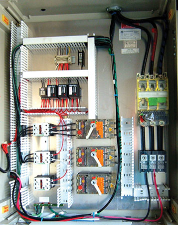
The last item we will discuss is Article 409, Industrial Control Panels, which may seem like a stretch for a combination inspector, and, in reality, I agree. From my experience, the usual path to acceptance of industrial control panels is requiring that the control panel be inspected and labeled by a third party NRTL. The NRTL representative does his inspection according to UL 508 Standard for Industrial Control Panels. So as an inspector, when it comes to a control panel, you basically have a choice. The first option is to ask that it be inspected and labeled by a third party NRTL to UL 508; the second option is for you to study Article 409 and do the inspection yourself. In my department, my inspectors were not familiar with 409. Although they could have learned it, we just did not have the time to inspect a control panel thoroughly due to the high volume of work within the department. Having done control work myself, I was the only one comfortable doing these inspections, but you literally have to inspect every item within the equipment. The department did not feel like the amount of time it took to perform the inspection was justifiable, so word got out very quickly that all control panels had to have a UL 508 listing in order to be used in our jurisdiction.
In the next issue, we will continue reviewing the articles in Chapter 4. Please use your codebook to review the items we covered.