
As we continue our journey through Chapter 4 in the 2011 National Electrical Code, I will point out highlights in the material that I believe will be most relevant for inspectors. These articles cover issues related to appliances, motors and air-conditioning equipment. Since I plan to only point out what I consider to be the key issues in these articles for inspections, we will be skipping quite a bit of each article. Again, I would encourage you to get out your code book and please read the entire article to familiarize yourself with everything that is included in the code.
Starting in Article 422 Appliances, let’s first look at 422.16 Flexible Cords. In dwelling construction, we have several types of appliances that are typically installed and many of these are connected to our branch circuits through the use of flexible cords and plugged into receptacles. Starting with kitchen waste disposers in 422.16(B)(1), we see that you have to use a cord that is identified as suitable for the purpose by the appliance manufacturer. Usually this is a flat appliance cord. There are further restrictions: first, it has to be a grounding type attachment plug; second, the length of this cord must be between 18 inches and 36 inches. This cord must be protected from physical damage. Physical damage is an undefined term in the NEC, but we hope that you will know it when you see it. Lastly, the receptacle that the disposal is plugged into must be accessible.
The next item we come to includes the dishwasher and trash compactor. Neither of these items refers to your teenage kids. We are talking about the electrical type of appliances, although at times we might like to jolt our kids. The language in 422.16(B)(2) is very similar to what we found for disposals except the permitted length of the cord, which is required to be between 3 feet and 4 feet.
Wall-Mounted Ovens and Counter-Mounted Cooking Units are the next things we find in 422.16. Here we have the choice of permanently connecting these items or using a cord-and-plug connection. I will share my experience with these, having seen thousands of these appliances installed during the housing boom in Southern Nevada during the late 1990s and 2000s. Commonly, the electrician installs the branch circuit to a junction box for the oven or range. When the appliances are delivered, they are connected by personnel of the trucking company that delivers them. Because of this installation by unqualified persons, we have had many code violations in the wiring methods used for the final connections, including everything from twist-on connectors (one brand name is Wire-Nuts) for 6 AWG and 4 AWG conductors to aluminum and copper conductors connected together without the use of proper listed connectors. When we bought the house where I live now, it had a double oven and we decided to change it out for a microwave and single oven. When the original oven was removed, we found 6 AWG aluminum connected to 8 AWG copper with red wire nuts, without even the benefit of oxide inhibitor.
I prefer to have electricians doing electrical work, and several local electrical contractors asked me about their liability issues in these cases. All I could tell them was to make sure the general contractor allows them to do the final connection, or that they should install range receptacles so that we have a clear line of where the electrician’s work ends and the appliance’s delivery person’s work begins. Basically, just like any other receptacle circuit in the house, the electricians are not responsible for whatever is plugged in. The only issue here is that you have to make sure the appliance you are using permits a cord-and-plug connection as part of its listing.
Range Hoods are covered in the next section; again, the language is similar, and in this case the length of the cord is again 18 inches to 36 inches. This is actually a real convenience since these range hoods are often changed out to combination microwave-hood units. Having a receptacle so that the customer can simply unplug the range hood and plug in the new microwave is much safer for the future homeowner.
The last thing I will cover in Article 422 is 422.18 Support of Ceiling-Suspended (Paddle) Fans. These are considered an appliance, so they are also covered in this article. Basically, the language calls for the fan unit to be independently supported or to be supported by an outlet box or system that is listed for the support of fan units. It also refers us back to 314.27(C), where we find more details on the requirements for this listed box.
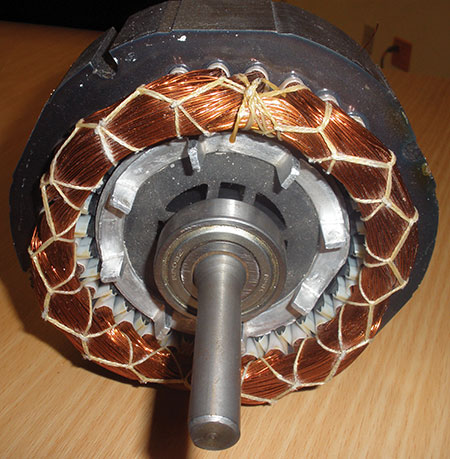
Let’s jump to Article 430 Motors, Motor Circuits and Controllers. We are going to take a high level fly-over of this article. I will cover the basics related to common motor installations, motor conductor sizing, short-circuit and ground-fault protection, and overload protection. First of all, please note that there is a distinct separation for motors related to short circuit, ground fault and overload protection. When we get to motors, this protection is generally provided by two separate devices. Article 430 is one of those articles that provides us with a road map to follow in Figure 430.1. One item I’ve recommended to those that I’ve taught the code to in the past is to take the time and put the page numbers next to each line of this diagram; this will help you get to the right place when in a hurry or taking a test.
The first item to learn is that for normal motors we use the nameplate information of the motor only to find the horsepower rating, phase and voltage of the motor. We then take this information and go to the tables in Article 430 to find the full-load current used to calculate the wire size and the short-circuit and ground-fault protection. The only time we use the ampere rating on the motor nameplate is when we do the overload protection, and I will explain that later in this article.
So let’s start with finding out what size conductor the code requires for a motor. Look at the nameplate to find the horsepower, phase and voltage of the motor. Immediately, proceed to either table 430.248 for single-phase motors or 430.250 for three-phase motors. Let’s choose a single-phase, 115 V, 1.5 hp motor. Scan down the left column to find your horsepower and then follow that row across to the current value that corresponds with the voltage (20 amps). Write down the ampere value from the table. This is the value we will use for both the conductor sizing and short-circuit and ground-fault sizing.
To find the conductor size, we take our current value and go to Part II of Article 430, specifically 430.22 that states the conductor size will be 125% of the current value for a continuous duty motor. The duty rating of the motor will be marked on the nameplate. If your current value is 20 amps, then the conductor has to be good for 25 amps. When we go to Table 310.15(B)(16) we see that a 12 AWG copper is good for this current value in the 75 degree C column. This is the column we commonly use as outlined in 110.14(C)(1)(a)(4).
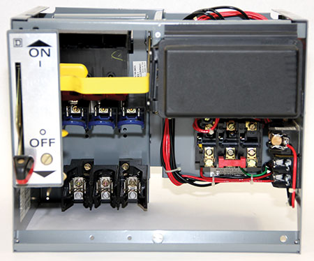
Now let’s look at our short-circuit and ground-fault protection sizing. First, we have to decide if we are going to use fuses or circuit breakers for this protection. Part IV deals with this protection and we go to 430.52(C)(1), which tells us to use Table 430.52. Using the value of 20 amps for our motor, we see that for an inverse time breaker (which is the style commonly used), we can use 250 percent of our 20 amps. If we are using dual element time delay fuses, then we use 175 percent. Doing the math, we find out that we can use a 50-amp breaker or a 35-amp fuse, both of which are standard sizes according to 240.6. Now I will give you a personal opinion here: the language in 430.52(C)(1) states that the protective device shall have a rating not exceeding the calculated value, which we just used. To me, this requirement tells me that we are required to round down if the calculated value doesn’t match a size listed in 240.6. But, fear not, we have an exception which permits us to round up to the next standard size [see exception number 1 to 430.52(C)(1)]. However, from my experience, unless the application has a very heavy load at startup there is no need to go up in size. In the interest of providing better protection, I have always taken the “not exceeding” language to heart and rounded down.
Have you noticed that we have a 12 AWG conductor with a short-circuit and ground-fault protective device that is either a 50-amp breaker or a 35-amp fuse? Is this really permitted? What about Article 240 where it states that the maximum protection for 12 AWG copper is 20 amps? Please review Table 240.4(G) and you will find Article 430 listed as one of the areas considered as a specific conductor application. So the answer is yes, this really is permitted and it is a perfectly good, code-compliant installation. Don’t worry if you didn’t know this before, it is one of the items that is very often not properly enforced.
Our next step is to figure out how to protect the motor from overloads using one of the means in 430.32. So how do we size the motor overload device, which is separate from the other circuit protection we have already calculated? This is where we use the nameplate current rating as mentioned in 430.6(A)(2). In Part III, specifically 430.32(A)(1), we find three ranges for overload protection that depend on the rating of your motor. If it is marked with a service factor of 1.15 or a temperature rise of 40 degrees C, we can use a value of 125 percent of the nameplate current rating. Frequently you won’t find these types of motors, so for all other motors the sizing is 115 percent of the nameplate current rating. Let’s take our example motor, for which table 430.248 listed a full-load current value of 20 amps, but the nameplate is labeled at 18 amps. If it is just a standard motor, then we multiply 18 amps times 115 percent and find the overload protection shall be 20.7 amperes. This value is completely different from what we are used to seeing in breakers and fuses; however, if you look in the motor starter (which has a horsepower size rating to match your motor), you will find overload sizing broken down to a fraction of an amp. You can then match the overload device units to provide the protection calculated.
Let’s step back and look at the overall picture for a moment. We are wiring a motor that has overload protection to open the motor controller if the current draw exceeds either 115 or 125 percent, depending on the motor. If our conductor feeding that motor is sized at 125 percent then do we have the conductors protected from an overload? Yes, so we have overload protection of the conductors being provided by the overload device for the motor. If there is a short circuit or ground fault, then the breaker or fuse will provide the fast reacting protection required for the high-fault current condition. This method of determining overcurrent protection appears quite different when compared to normal wiring methods, but as you can see, it works to provide the protection we need for motors.
Next, let’s look at the other two things we do when it comes to motors: sizing a feeder for multiple motors and sizing the short-circuit, ground-fault protective device for that feeder. This is covered in 430.24, which states that you take the largest motor rating you found in Tables 430.248 or 430.250, multiply it by 125 percent, then add the sums of the rest of the motor values you found in the table. If your largest motor has a value of 100 amps, then 125 percent of 100 amps is 125 amps. Let’s say the other motors are 50 amps, 25 amps and two at 10 amps, for a total of 220 amperes. Take that value and again use Table 310.15(B)(16) to find a conductor that is sufficient for the 220 amps.
Now let’s find a breaker or fuse to protect this feeder. In Part V, 430.62 we find that we take the largest individual fuse or breaker from our individual protection calculation; then from that value, we add the sum of all the other motor loads on that feeder. Again, these values are based on the tables. Using the numbers we found for the feeder and starting with fuses: 100 amps multiplied by the 175 percent gives us 175 amps; then add in the other four motors to find a value of 270 amps, so we would have to use a 250-amp fuse for the feeder. Using breakers, it would be 100 amps times 250 percent for a value of 250 amps plus the other motors, which gives us 345 amps. We would use a 300-amp breaker for the feeder.
I hope this has simplified motor calculations. There is a lot of information in Article 430, but I have covered the areas that in my experience are the most commonly used and needed during the inspection process. Please take the time to review each of the sections I have mentioned above and look at some of the other language found in Article 430.
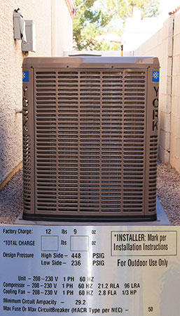
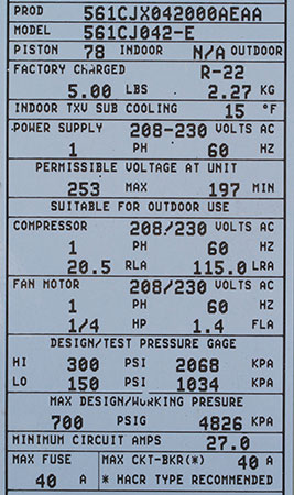
So when it comes to Article 440, what do we do? In close to three decades of electrical work, I don’t think I have had to use language in Article 440 more than a handful of times. Why is that, you may ask, haven’t you ever installed an air conditioner? Yes, and I have inspected thousands, but here is the secret: this equipment has a requirement that the manufacturer does this work for us and the information is found on the nameplate per Article 440. All we look for when it comes to A/C units is two things, the first of which is Minimum Circuit Ampacity (MCA). This value gives us the minimum conductor size required for this equipment. It is based on 125 percent of the largest load plus the sum of all the other motors. Sound familiar?
Second, we read the label for the Maximum Fuse or Maximum Circuit Breaker. Again, they have done the math and we just have to make sure the installed fuse or breaker does not exceed this value. Pay careful attention, since at times the nameplate may give the option to only use a breaker, only use a fuse, or allow the use of either a breaker or fuse. Make sure it is installed exactly as the label states, since if it only gives a value for fuses, then the equipment is tested and listed to be protected by fuses only, and likewise for circuit breakers.
I hope this information helps when inspecting motors and A/C equipment. Make sure you review the code language along with reading this article to fill in the voids of what I haven’t specifically covered.