This is the third of a series of five articles detailing significant changes approved by the Technical Committee for the 2018 Canadian Electrical Code Part I (CE Code). The final meeting for 2018 CE Code changes took place in June 2017. It should be noted that the 2018 CE Code was published by CSA Group on January 1, 2018, and the information provided in this article is based solely on the consolidated memorandum of revisions to the CE Code, published by CSA Group after the June meeting.
Section 12-*+ — Wiring methods
The first significant rule change in Section 12 is found in Rule 12-012. Subrule (8) has been modified to recognize permission for installation of armoured or metal sheathed cables suitable for direct burial with a reduced depth under a concrete slab in the same manner as raceways. In addition, these underground installations will be required to be marked in a conspicuous, legible and permanent manner.
Section 12 has been revised to reflect wiring installation requirements that used to be located in Section 4. To allow space for these rules, Rule 12-400 of the 2015 CE Code for bare busbar and risers was moved to new Rule Number 12-2600, and the relevant 2015 CE Code Section 4 rules were moved to Section 12 including the Appendix B notes and the table references as follows:
4-008 Insulated conductors moved to Rule 12-102 as Subrules (3) and (4).
4-012 moved to new Rule Number 12-402 Uses of flexible cord
4-018 moved to new Rule Number 12-404 Flexible cord used in show windows or show cases
4-020 moved to new Rule Number 12-122 Equipment wire
4-040 moved to new Rule Number 12-406 Uses of portable power cable
4-040 moved to new Rule Number 12-406
The next significate change in Section 12 is to reword Subrule (2) of Rule 12-106 to mandate restrictions for insulated conductors in a multi-conductor cable used for connection to different power or distribution transformers or other different sources of voltage, similarly to existing restrictions on installation of conductors in raceways of Rule 12-904(2).
Rule 12-910 Conductors and cables in conduit and tubing has a new Subrule (6) that will not allow Table 6 to be used with HDPE conduit from the new CSA Standard C22.2 No. 327-16 HDPE conduit, conductors-in-conduit, and fittings. The reason for this limitation is that HDPE conduit has a smaller internal diameter than other circular raceway types. To allow the installation of HDPE conductors-in-conduit Subrule (1) of Rule 12-938 now has an exception to the requirement that raceways must be completely installed prior to installation of the insulated conductors. More information on HDPE conduit and HDPE conductors-in-conduit can be found in the January / February IAEI magazine article. https://iaeimagazine.org/2016/01/18/hdpe-conduit/. The introduction of HDPE conduit resulted in six new tables added to Table 9 as Tables 9K to 9P, and installation requirements in new Rules 12-1250 to 12-1268.
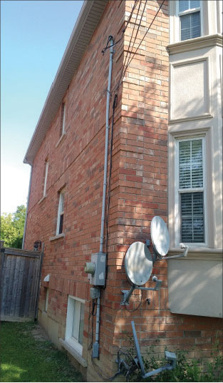
The requirements in Rule 12-934 for protection of raceways installed less than 2 m above grade in lanes and driveways has been reworded and expanded to include all installations of raceways located at less than 2 m above grade and subjected to mechanical damage.
Rules 12-1122 and 12-1414 Provision for bonding continuity now has a Subrule (2) allowing PVC conduit and electrical metallic tubing used as a consumer’s service raceway without a separate bond conductor unless mandated in other sections of this Code.
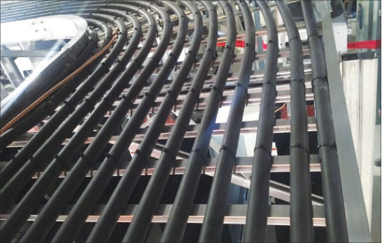
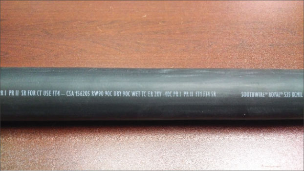
Rule 12-2202 that applies to installation of insulated conductors and cables in a cable tray, has three significate changes. The first change is the impact the new definitions of “cable” and “insulated conductors” have on the clarity of this rule. The second change relates to the requirement for fastening of insulated conductors and cables at intervals not exceeding 1.5 m to prevent excessive movement that may be caused due to fault current magnetic forces, and to the requirement for minimum spacing in order to ensure ampacity values are maintained. The third change allows Type TC-ER tray cable to be used for transition between cable trays, and between cable trays and utilization equipment or devices for a distance of not more than 1.5 m without continuous support and not exceeding 7.5 m where continuously supported.
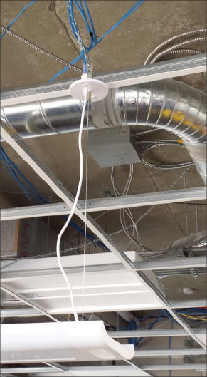
New Subsection 12-2300 has been added for extra-low voltage suspended ceiling power distribution systems. This subsection includes special terminology definitions. Extra-Low Voltage Suspended Ceiling Power Distribution System is defined as “An extra-low voltage system that serves as a support for a finished ceiling surface and consists of a busbar and busbar support system to distribute power to utilization equipment supplied by a Class 2 power supply.”
This subsection also includes installation requirements, permitted use, prohibited use, Class 2 limitations, disconnecting means, securing and supporting, connectors, reverse polarity protection, and system grounding requirements.
The device box calculation used to determine space occupied by a device having a dimension greater than 2.54 cm in Subrule (3) of Rule 12-3034 has been simplified. The calculation is now: 32 cm3 multiplied by the depth of the device in centimetres.
Section 14 — Protection and control
Section 14 has only one significant rule change found in Rule 14-104 Rating of overcurrent devices. The exception allowed by Subrule (1) Item (a) now has a reference to the maximum load in accordance with Section 8 when selecting the overcurrent device for conductor protection. This exception also recognizes that Table 13 now could apply to a maximum value of 800 A instead of 600 A. Table 13 has been revised accordingly.
Section 16 — Class 1 and Class 2 circuits
The scope of Section 16 has been expanded to include Class 2 power and data communication circuits connecting power sourcing equipment and powered devices, also known as power over ethernet cables.
In addition to Class 2 transformers, Rule 16-200 now recognises other power supply device having a Class 2 output. Subrule (4) was added to recognize that a device having a Class 2 output is permitted for use as a device having energy-limiting characteristics, provided that it is marked as being suitable for the purpose. Appendix B Note for Subrule (4) clarifies that, Class 2 power supplies can be certified to any of the following standards:
CAN/CSA-C22.2 No. 60950-1 for limited power supplies (LPS);
CSA C22.2 No. 223 for power supplies with extra-low-voltage Class 2 outputs;
CSA C22.2 No. 66.3 for Class 2 transformers;
CAN/CSA-C22.2 No. 62368-1 for audio/video, information and communication technology equipment; and
CAN/CSA-C22.2 No. 250.13 for light emitting diode (LED) equipment.
The marking requirements for a Class 2 power supply in Rule 16-204 mandate the marking to indicate suitability for wet locations when intended for wet locations.
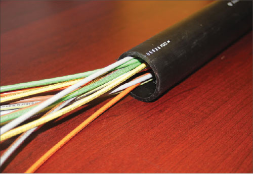
A new Subrule (5) has been added to Rule 16-212 to allow electric lighting, power, and Class 1 circuit conductors in a cable that contains Class 2 circuit conductors insulated for the maximum voltage in the cable and intended for connection to remote devices associated with the non-Class 2 conductors. This subrule recognises cables like AC-PCS cables intended for power, control, and signal applications.
The wording “current-limiting devices” in Rule 16-222 was replaced with “devices having a Class 2 output”; this aligns Rule 16-222 with Rule 16-200. In addition, Subrule (3) has been added to provide consistency between CSA Standard CSA C22.2 No. 223-15 Power supplies with extra-low-voltage Class 2 outputs limiting the operating voltage of Class 2 circuit as follows:
“(a) dry or damp locations when the voltage characteristics are:
(i) 30 V rms for sinusoidal ac;
(ii) 42.4 V peak for other waveforms (nonsinusoidal ac);
(iii) 60 V continuous dc; and
(iv) 24.8 V peak for interrupted dc (square wave dc at a rate of 10 to 200 Hz)
(b) For wet locations (immersion not included):
(i) 15 V rms for sinusoidal ac;
(ii) 21.2 V peak for nonsinusoidal ac;
(iii) 30 V for continuous dc; and
(iv) 12.4 V peak for interrupted dc (square wave dc at a rate of 10 to 200 Hz)”
Subsection 16-300, Subrule (7) for Rule 16-210, and Table 60 were added to provide direction for Class 2 power and data communication circuits (power over ethernet cables). This direction includes equipment output limitations, cables and conductor ampacity, wiring methods marking requirements, and special terminology definitions for, cable bundle, Class 2 power and data communication circuits, powered device, and power sourcing equipment.
Section 18 — Hazardous locations
Throughout Section 18 the term “powder-filled” was replaced with “powder filling” and the term “flame-proof” was replaced with “flameproof”.
In Rule 18-002 Special terminology the following definitions were changed or added:
Descriptive system document has a new definition that reads “document in which the items of electrical apparatus, their electrical parameters and those of the interconnecting wiring are specified.”
The definition for Explosive gas atmosphere has been revised to read:
“a mixture with air, under in the form of gas or vapour, in which, after ignition, permits self sustaining flame propagation.”
The definition for Explosive limits was changed to “Flammable limits” to be consistent with terminology used in relevant NFPA standards and revised to read:
“The lower and upper percentage by volume of concentration of flammable gas or vapour in air that will form an ignitable mixture.
LFL — lower flammable limit.
UFL — upper flammable limit.”
This editorial change is consistent throughout Section 18.
Other new definitions include Intrinsically safe circuit, Intrinsically safe electrical system, Hazardous location cables, and Non-incendive field wiring circuit, that read:
“Intrinsically safe circuit — circuit in which any spark or any thermal effect produced under prescribed conditions, which include normal operation and specified fault conditions, is not capable of causing ignition of a given explosive atmosphere
Intrinsically safe electrical system — assembly of interconnected items of electrical equipment, described in a Descriptive System Document, in which the circuits or parts of circuits intended to be used in a hazardous location are intrinsically safe.
Hazardous location cables — cables that bear an “HL” marking.
Non-incendive field wiring circuit — a circuit described in a Descriptive Systems Document, in which any spark or thermal effect that may occur under normal operating conditions or due to opening, shorting, or grounding of field wiring is not capable of causing an ignition of a given explosive atmosphere.”
Rule 18-004 Classification of hazardous locations, has been expanded adding three subrules that require the documentation and classification of hazardous locations to be carried out and authenticated by qualified persons. Notwithstanding, this additional classification is not required for installation within the scope of Section 20.
Rule 18-052 Marking, was modified by moving the marking requirements for installations in hazardous locations to Appendix B.
Rule 18-054 Temperature, these four subrules were reworded clarifying that “the maximum surface temperature rating marked on equipment shall not exceed the minimum ignition temperature determined for the hazardous location in which the equipment is installed”. In addition, for equipment installed in Zone 0, 1 and 2 locations where no maximum surface temperature rating is marked on the equipment the maximum surface temperature rating shall be deemed to be 100 °C.
Rule 18-064 Intrinsically safe and non-incendive electrical equipment and wiring, the five subrules in 2015 CE Code were replaced with eight new subrules. The first two subrules require intrinsically safe electrical system or non-incendive field wiring circuit to be installed in accordance with a descriptive systems document that must also be provided.
Subrule (3) details separation required between insulated conductors of intrinsically safe or non-incendive field wiring circuits and insulated conductors of any other circuit with the following separation:
“(a) not less than 50 mm;
(b) the metal armour or sheath of cable assemblies;
(c) a grounded metal barrier not less than 1.34 mm (No. 16 MSG) thick; or
(d) a non-metallic insulating material not less than 1.5 mm in thickness.”
Subrule (4) allows a raceway, compartment, outlet, junction box, or multi-conductor cable to be used for insulated conductors of different intrinsically safe or non-incendive field wiring circuits were:
“(a) the insulated conductors of each circuit are within grounded electrically conductive shields, braids, or sheaths; or
(b) the insulated conductors of each circuit have insulation with a minimum thickness of 0.25 mm.”
Subrule (5) mandates the migration of flammable fluids to other locations to be minimised where raceways or cable systems are used for wiring of intrinsically safe or non-incendive equipment in explosive atmospheres.
Subrule (6) requires all apparatus forming part of an intrinsically safe and non-incendive system shall be identified as being part of an intrinsically safe and non-incendive system.
Subrule (7) mandates identification at terminal and junction locations for intrinsically safe and non-incendive field wiring circuits.
Subrule (8) requires that where wiring methods other than cables or insulated conductors coloured light blue are used intrinsically safe and non-incendive field wiring circuits, the wiring methods must be identified with permanently affixed labels.
Table J1.2 covering acceptable equipment comparison for explosive gas atmospheres has been moved to a mandatory table. This accompanies a change to Rules 18-090, 18-100, 18-150, 18-190, 18-200 and 18-250, to require equipment installed in hazardous location to be in accordance with the moved table.
New Rule 18-092 Wiring, Zone 0 has been inserted detailing that wiring shall be intrinsically safe. In addition, New Subrule (2) allows cables marked HL used for non- intrinsically safe circuits to pass though a Zone 0 location provided the cable is protected from mechanical damage and that the cable extends beyond the boundary by 300 mm without fittings or connections.
Rule 18-102 has a new Subrule (7) that allows wiring methods for intrinsically safe equipment and associated circuits, designed and installed as “ia”, “ib”, or intrinsically safe to be installed for Class l locations.
Rule 18-152 Wiring methods, Zone 2, a new Item (h) has been added to Subrule (1) allowing liquid-tight metal flexible conduit and connectors, marked as heavy duty to be used for Zone 2 locations.
Rule 18-152 has a new Subrule (8) that allows wiring methods for intrinsically safe equipment and associated circuits, designed and installed as “ia”, “ib”, “ic”, or intrinsically safe to be installed for Class II locations.
Rule 18-192 Wiring methods, Zone 20, has a new Subrule (5) that allows wiring methods for intrinsically safe equipment and associated circuits, designed and installed as “ia”, “ib”, “ic”, or intrinsically safe to be installed for Class II or Class III locations.
Rule 18-202 Wiring methods, Zone 21 has a new Subrule (6) that allows wiring methods for intrinsically safe equipment and associated circuits, designed and installed as “ia”, “ib”, or intrinsically safe to be installed for Class II or Class III locations.
Rule 18-252 Wiring methods, Zone 22 has a new Subrule (5) that allows wiring methods for intrinsically safe equipment and associated circuits, designed and installed as “ia”, “ib”, “ic”, or intrinsically safe to be installed for Class II or Class III locations.
Section 20 — Flammable liquid and gasoline dispensing, service stations, garages, bulk storage plants, finishing processes, and aircraft hangars. All references to Class I have been removed from Section 20 to align with Section 18 Zone based terminology. The hazardous locations within Section 20 are now Zone 0, Zone 1, or Zone 2.
Rule 20-202 Hazardous areas, Subrules (1) though (7) were deleted and replaced with one sentence that refers code users to New Table 69 Hazardous Locations at Bulk Storage Plants to determine the hazardous location classifications.
Section 22 — Locations in which corrosive liquids, vapours, or excessive moisture are likely to be present.
Section 22 does not have any significate changes for this code cycle.
Section 24 — Patient care areas
The first significant change in Section 24 is the addition of a new definition in Rule 24-002 Special terminology for Health care facility administration that reads: “the unit responsible for planning, organizing, directing, and controlling the health care facility in accordance with the policies”
Rule 24-102 Circuits in basic care areas, has a newly inserted Subrule (5) and reworded Subrules (3) and (4) for patient care environment branch circuit loads that are required to be supplied from an essential electrical system. Branch circuits for these patient care environments are to supply only loads within that patient care environment or to supply loads located only in two adjacent patient care environments.
In addition to editorial changes to Rule 24-104 Bonding to ground in basic care areas, A new Subrule (9) allows luminaires installed at 2.3 metres and greater above floor level, and their associated switches that are located outside a patient care environment to be bonded in accordance with Section 10 (and not in accordance with Section 24).
In Rule 24-204 Single-phase isolated circuits, Item (f) of Subrule (2) was deleted allowing other than non-metallic raceways for isolated circuit wiring. In addition, for a single-phase isolated system the total impedance between ground and each energized conductor has been reduced from 500,000 Ω to 200,000 Ω. The rationale for these changes was based on IEEE 602-2007, Recommended Practice for Electric Systems in Health Care Facilities.
Loads of an essential electrical system described in Section 24, also include loads of a life safety system governed by Rules of Section 46. Thus, Rule 24-302 has been revised so, as to clarify this fact. Item (a) of Subrule (2) now references life safety in accordance with Section 46, and a new Subrule (4) was added allowing insulated conductors required for operation of life safety systems installed between an emergency power supply and life safety systems to be installed without separation from other insulated conductors of essential electrical system, provided that overcurrent devices protecting circuits of the essential electrical system are all selectively coordinated, or the conditional branch (24-hour power restoration) circuits are kept entirely separate from the delayed vital branch (2-minute power restoration) and vital branch (10-second power restoration) circuits.
Rule 24-306 Emergency supply, has been reworded to mandate the emergency supply to be in accordance with CSA Standard Z32, and to be installed in a service room or enclosure on the health care facility premises in accordance with CSA Standard C282. The change was implemented due to the need to correlate relevant provisions of the CSA standards Z32 and C282 in respect to the emergency power supply.
The next article will cover CE Code changes for Sections 26 to 62.