Why is visible isolation required for high voltage circuits?
High voltage visible isolation has been required in Canada since the fifties. Visible isolation is the ability to see the blades of a switch or circuit breaker to determine if the device supplying a high voltage circuit is in the open or closed position. Keep in mind that high voltage as defined by the Canadian Electrical Code Part I (CE Code) is any voltage over 750 V. The main two CE Code rules requiring visible isolation of disconnecting means are 36-204 and 36-214. The current wording reads:
36-204 Overcurrent protection
(1) Each consumer’s service, operating unit of apparatus, feeder, and branch circuit shall be provided with overcurrent protection having adequate rating and interrupting capacity in all ungrounded conductors by one of the following:
(a) a circuit breaker;
(b) fuses preceded by a group-operated visible break load-interrupting device capable of making and interrupting its full load rating and that may be closed with safety to the operator with a fault on the system; or
(c) fuses, preceded by a group-operated visible break air-break switch that is capable of interrupting the magnetizing current of the transformer installation, that may be closed with safety to the operator with a fault on the system, and that, to prevent its operation under load, is interlocked with the transformer’s secondary load interrupting device.
(2) Fuses shall be accessible to authorized persons only.
36-214 Disconnecting means
(1) Where conductors fed from a station enter a building, either
(a) a load-breaking device shall be installed indoors at the entry of the conductors to the building; or
(b) a load-breaking device at the supply station shall be capable of being tripped or operated from within the building.
(2) Unless of the draw-out type, each circuit breaker and each load-break switch having contacts that are not visible for inspection in the open position shall be provided with a group-operated isolating switch on the supply side that shall be
(a) provided with the means for adequate visible inspection of all contacts in both the closed position;
(b) interlocked so that it cannot be operated under load; and
(c) provided with positive position indicators.
(3) Where more than one source of voltage exists in a station consisting of two or more interconnected sections operating at high voltage or where there is another possibility of feedback, a visible point of connection meeting the requirements of Subrule (2) shall be provided in all circuits where the possibility of feedback between sections exists.
Visible isolation was first introduced into the 1953 edition of the CE Code in Rule 8-024 Overcurrent Protection, Services, and Rule 8-028 Disconnecting Means.
8-024 Overcurrent protection, services
Each service shall be provided with overcurrent protection, complying with the following, in all ungrounded conductors;
(a) If the protective equipment is installed outdoors, one of the following shall be used:
(i) Circuit breaker of adequate interrupting capacity and rating, with trip settings approved by the supply authority;
(ii) Fuses of adequate rating and interrupting capability preceded by a suitable group-operated visible break load-interrupting devices capable of making and interrupting their full load rating and which may be closed with safety to the operator with a fault on the system;
(iii) Fuses of adequate rating and interrupting capacity proceeded by a group-operated visible break air-break switch capable of interrupting the magnetizing current of the transformer installation and which may be closed with safety to the operator with a fault on the system and so interlocked with the transformer secondary to prevent its operation under load.
(b) If the protective equipment is installed indoors, one of the following shall be used:
(i) The protection outlined in paragraph (a) (i) of this rule;
(ii) The protection outlined in paragraph (a)(ii) of this rule by special permission and where satisfactory to the supply authority, provided that the load-interrupting devices and fuses are separated and interlocked so the operator cannot gain access to fuses with the load-interrupter devices closed.
(iii) The protection outlined in paragraph (a) (iii) of this rule by special permission and where satisfactory to the supply authority, provided that the fuses are separated and interlocked so that the operator cannot gain access to them unless the switch is open and the switch is interlocked so that it cannot be operated under load.
8-028 Disconnecting Means
(1) At least one group-operated isolating switch shall be placed on the supply side of each service circuit breaker, except were equipment of the draw-out type or group-operated load-interrupting devices are installed, and shall;
(a) Visibly disconnect all ungrounded conductors of the service; and
(b) Be interlocked so that it cannot be operated under load.
(2) In cases where possible feed back exists, group-operated isolating switches shall be installed to meet this condition.
Regarding visible isolation Rule 8-028 was revised in Rule 36-214 of the 1982 CE Code edition requiring the contacts to be visible in both the open and closed positions.
36-214 Disconnecting means
(1) Where conductors fed from a station enter a building, either
(a) a load-breaking device shall be installed indoors at the entry of the conductors to the building; or
(b) a load-breaking device at the supply station shall be capable of being tripped or operated from within the building.
(2) Unless of the draw-out type, each circuit breaker and each load-break switch having contacts that are not visible for inspection in the open position shall be provided with a group-operated isolating switch on the supply side that shall be
(a) provided with the means for adequate visible inspection of all contacts in both the open and closed position;
(b) interlocked so that it cannot be operated under load; and
(c) provided with positive position indicators.
(3) Where more than one source of voltage exists in a station consisting of two or more interconnected sections operating at high voltage or where there is another possibility of feedback, a visible point of connection meeting the requirements of Subrule (2) shall be provided in all circuits where the possibility of feedback between sections exists.
The requirement remained unchanged until the 2012 Edition of the CE Code where the requirement to see the contacts in the closed position was deleted resulting in the current wording.
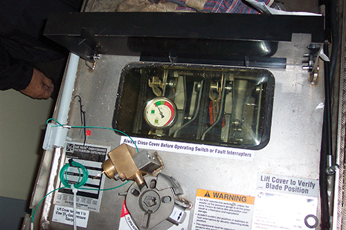
The intent of theses rules is to have installations where qualified persons working on the high voltage circuit have the capability to view the contacts in the switch or breaker for the circuit to see the open contacts before applying a lock-out tag-out lock and checking for voltage on the circuit to be worked on.
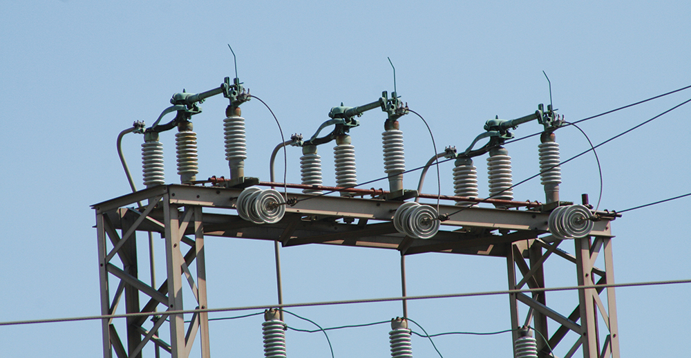
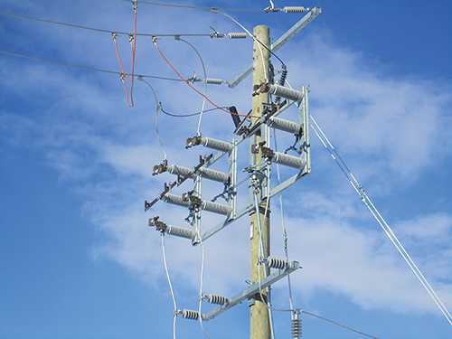
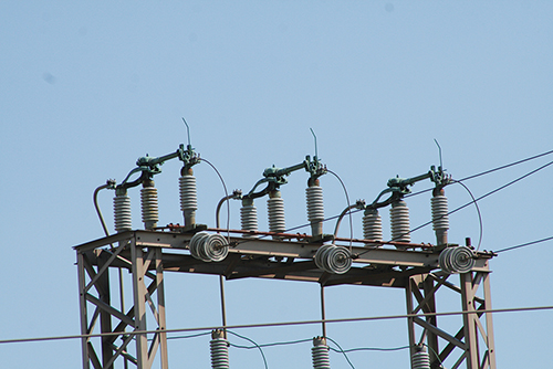
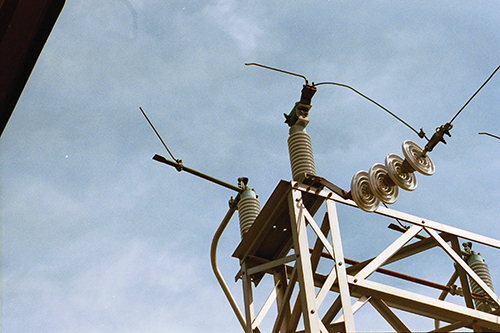
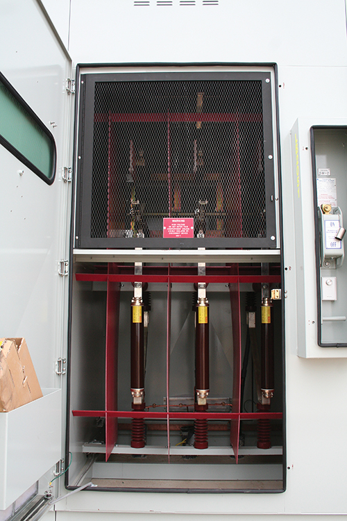
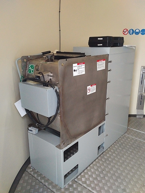
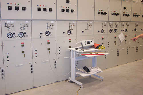
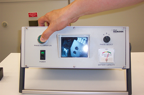
Examples of visible isolation include: air-break switch, load-break switch, circuit breakers with viewing windows, FS6 breakers and switches with viewing windows or cameras, and draw-out breakers and switches. Note when an air-break switch is used, interlocking is required to prevent operation of the switch under load.
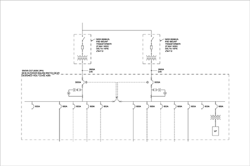
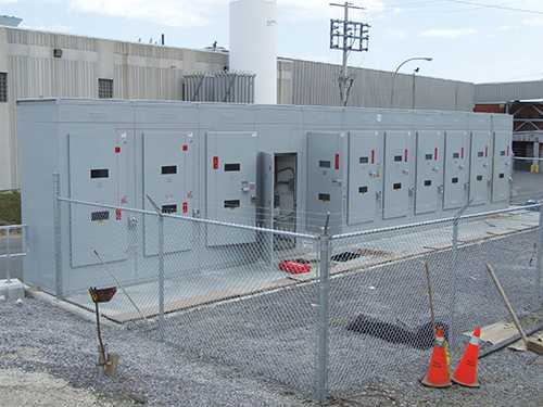
Not all types of visible isolation are required in the high voltage circuit. As an example, a double ended station with two transformers that have low voltage secondary circuit connected together through a tie breaker. In this case, the two-main secondary low voltage disconnecting means are required to provide visible isolation. Photo 9 is a single line diagram of a double ended station. Note the two-main secondary low voltage 3000A breakers are of the draw-out type. This provides the visible isolation for a possible back feed into the high voltage circuit required by Subrule (3) of Rule 36-214.
Product standards also have requirements for visible isolation in accordance with the CE Code. As an example, CSA Standard C22.2 No 31 Switchgear requires visible isolation in Clauses 8.3.3, 8.3.4, 8.3.6, and F4.3.1.
Do all high voltage distribution circuits require visible isolation?
As with many rules of the code, the provision of Rule 36-214 has an exception introduced in the 2015 CE Code to Section 64. Rule 64-202(5) does not require visible isolation for photovoltaic source and output circuits with maximum voltages between 750 Vdc and 1000 Vdc.
64-202 Voltage of solar photovoltaic systems (see Appendix B)
(5) Photovoltaic source and output circuits with maximum voltages higher than 750 V dc but not exceeding 1000 V dc shall not be required to comply with Rules 36-204, 36-208, and 36-214.
This rule is also expanding for the 2018 CE Code to allow photovoltaic source and output circuits with a maximum voltage of 1500 Vdc to be installed without visible isolation.
2018 CE Code wording:
64-202 Voltage of solar photovoltaic systems (see Appendix B)
(5) Photovoltaic source and output circuits, and equipment connected to or within those circuits, with maximum voltages higher than 750 V dc but not exceeding 1500V dc shall not be required to comply with Rules 36-204, 36-208, and 36-214 provided that
(a) the installation is serviced only by qualified persons;
(b) the part of the installation exceeding 750V dc is inaccessible to the public; and
(c) enclosures in which photovoltaic source and output circuits exceeding 750V dc are present are marked with “DANGER” followed by the maximum rated photovoltaic circuit voltage of the equipment.
Note, additional provisions have been added in Items (a) though (c) of Subrule (5) requiring the installation for be serviced by qualified persons, the portion of the installation exceeding 750 V to be inaccessible to the public, and that enclosures with dc voltages exceeding 750 V must be field-marked to indicate the maximum voltage within the enclosure.
Other than the exception for photovoltaic source and output circuits, all individual high voltage distribution circuits require visible isolation.