The complexity of photovoltaic (PV) power systems dictates a careful and thorough inspection, starting with a detailed permit application and a plan review of the material submitted (IAEI, March-April 2017). Reviewing the detailed material submitted with the permit application may save many hours of inspecting and re-inspecting the installed PV system when deficiencies are found. After that plan review has been completed, the field inspection can be scheduled. In the following paragraphs, a few of the more important onsite inspection items are covered.
The Onsite Inspection
First impressions are important. Have you worked with this PV installer or systems integrator before? Is the site uncluttered and the system ready for inspection? Did they make the roof accessible in a safe manner? From a distance, does it look like good workmanship has been employed?
As with any electrical power system, attention to details during the installation process is critical, and the overall first impressions give some indication as to whether the installer has exercised good work procedures and habits.
Equipment installed to match the permit? The equipment that is installed should match the equipment that was listed in the permit application package. Variations in any components such as the PV modules or the inverter may necessitate recalculation of various parameters and the replacement of cables, overcurrent devices, and other equipment.
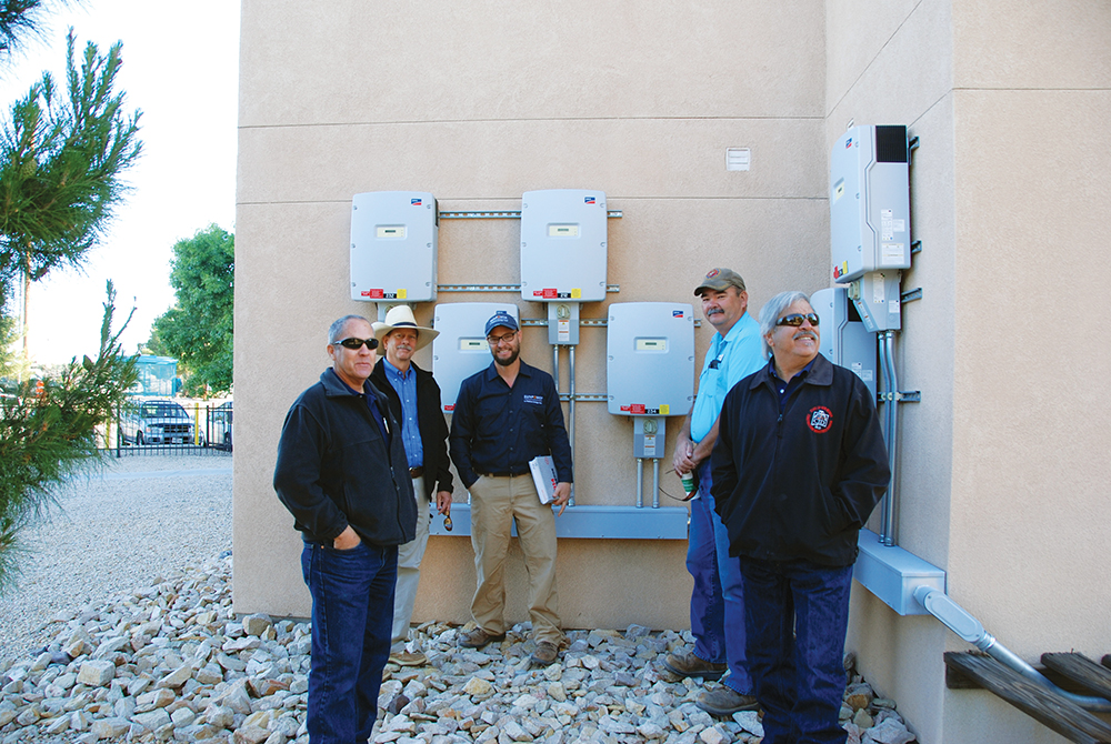
Let the installer operate the system. From a liability and safety point of view, it is usually a good idea to let the installer of the system perform all handling of the system components and operation of those components during the inspection (photo 1).
The installer should have the necessary tools and test equipment available to open equipment, make measurements, and exercise the equipment in various modes to demonstrate compliance with Code requirements. Unfortunately, the PV systems have reached a level of complexity that it is no longer possible to verify full code-compliance by just looking at a static assembly of wires, conduits, circuit breakers, PV modules, inverters and other equipment. In most cases, the equipment must be operated to demonstrate the proper safety features and compliance with NEC requirements.
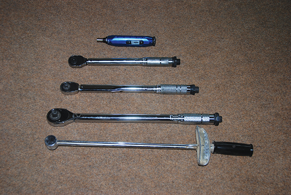
The installer should be able to show the torque screwdrivers and torque wrenches that were used in making the electrical connections and to show where the torque values for the various pieces of equipment can be found. All electrical contacts that are bolted or screwed must be torqued to the proper value to ensure a safe and durable connection. See 110.3(B). (Photos 2 and 3).
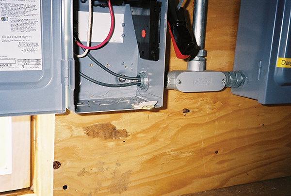
Proper grounding is critical for the long-term safety of the system. Before touching any parts of a new PV system, the equipment grounding systems from the PV modules to the main service panel and the grounding electrode(s) should be verified by visual inspection. The installer might be asked to show that various bolted grounding connections have been properly torqued and that conduit nuts and grounding bushings are tight. Grounding/bonding bushings should be used on all metal conduit fittings operating over 250 volts ac or dc (250.97) (photo 4).
On to the roof—Or not. What are some AHJ options when the local jurisdiction does not permit personnel to climb on the roof? The installer should be asked to provide close-up pictures of the PV module mounting and grounding methods and devices used. The pictures should show that the instructions for the module and rack mounting system were followed.
Although not required by Code, some jurisdictions are requiring the use of UL 2703 certified rack/mounting systems on the roof of residences. Since these racking systems cannot directly guarantee the quality of the actual attachment to the structure of the house, I think that any well-assembled module mounting and grounding system should suffice.
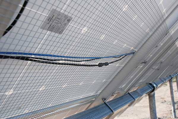
The same considerations might be given to ground-mounted installations where Unistrut embedded in concrete-filled holes might be judged an adequate mounting system. For ground-mounted systems that are readily accessible, the exposed single-conductor module wiring must be made “not readily accessible” by fencing or guarding (photo 5).
Instructions supplied with new modules will have the following phrase or equivalent: “This module remains certified to UL Standard 1703 only when mounted and grounded according to the included instructions.”
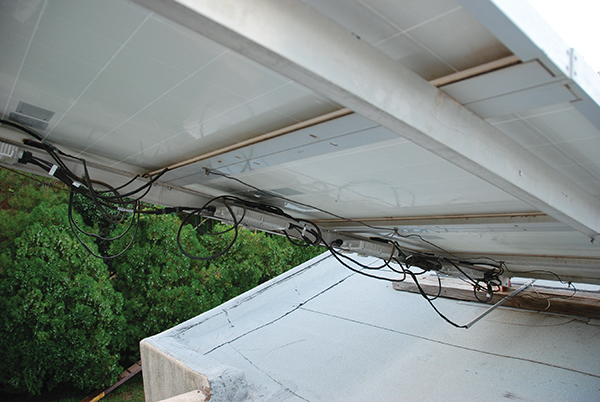
A picture of the back or underside of the array will indicate if the loose, single-conductor module wiring has been properly secured. Any conductors not well-secured for decades of use will be subject to wind-driven movement and possible abrasion of the insulation, creating a potential shock or ground-fault hazard in the future (photo 6).
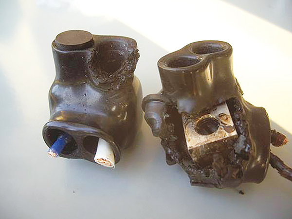
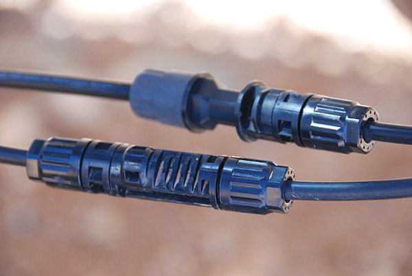
Another relatively recent issue in PV installations is the fact that the mating pairs of connectors used on modules and field-installed USE-2 and PV wire must be from the same manufacturer and of the same series. Even though connectors from two different manufacturers are said to be “MC-4 compatible,” they have not been tested and certified/listed with each other and therefore it would be a violation of the connector and module listing to use them together (photo 7).
The issue is that slight variations in the contact metals or alloys may allow galvanic corrosion over time and differences in the plastics used may create loose fittings due to differing expansion rates. At least one fire has been reported that may have been due to a mismatched pair of connectors. This issue will most likely show up where a field-installed run of USE-2 or PV wire is connected to the end of a string of PV modules and in dc-to-dc converters and microinverter connections to modules. The installer should confirm by pictures and/or technical information that all mated pairs of connectors are from the same manufacturer. Module instruction manuals or module markings will soon include the name of the connector manufacturer and the product series for the connectors being used on that module.
Eventually, the PV Industry will define and adopt a standardized, industry-wide connector that has a manufacturing standard and when connectors are manufactured and certified/listed to this standard, they can be used interchangeably like the ubiquitous interchangeable 120-volt ac plugs and receptacles that are made to a NEMA manufacturing standard.
Back on The Ground
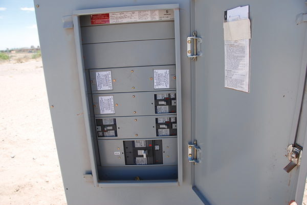
At the utility point of connection. In a 705.12(D) or (B)(2017) utility-interactive inverter output connection, the rating and location (position on the load center busbar) of the backfed PV breaker should be verified. The 120% or 100% rule should be met, and for the 120% rule, the backfed PV breaker(s) should be at the opposite end of the busbar from the main breaker (photo 8).
Many residences and commercial buildings have subpanels. Where subpanels are involved, attention must be directed to ensuring that any feeders or main-lug-only subpanels have appropriate ampacity or ratings to deal with backfed PV currents in the main panels adding to the currents from the main service breaker. In some cases, the feeder may be protected by a breaker at its source end, and the subpanel may be protected by a main breaker in that subpanel. If these protections are not afforded, the then ampacity of the feeder and the rating of the subpanel will have to be increased. Having the backfed PV breaker mounted in the last subpanel and in the last position in that subpanel will avoid some complications, but feeders and the main panel must be checked for Code compliance in Article 705.
For a supply 705.12(A) supply-side connection, the rating of the overcurrent protective device should be checked, and the location and wiring (utility connection to the top of any safety switch) of any utility required or used ac PV disconnect verified. The overcurrent device connected to the output of each inverter may not exceed the maximum overcurrent protective device as specified in the inverter installation manual; yet another reason to have the manual available during the inspection. The presence of the required overcurrent device within 10 feet of the service entrance connection point (705.31) should be verified.
It is the opinion of the author, since those (unnamed) conductors between the actual connection to the service-entrance cables and the first overcurrent protection device are subject to the full available fault currents from the utility and because those conductors may be smaller than the service-entrance conductors, they should be treated as service-entrance conductors per the requirements of Article 230 with respect to routing and mechanical protection.
After the System is Powered
With the complexity of modern PV equipment, full verification of the installation for safety and compliance with the NEC requirements (including Section 110.3(B) that requires compliance with equipment installation instructions) will usually require the AHJ to inspect the system during operation.
Verify equipment adjustments and settings. Equipment like string inverters, multimode inverters, charge controllers and PV Rapid Shutdown Equipment (PVRSE) may have software/firmware adjustments that must be properly made to ensure the safe and correct operation of the product [110.3(B)]. The AHJ should have the installer demonstrate that all adjustments have been completed in accordance with the product instruction manuals.
Pv Rapid Shutdown System (PVRSS).
The inspector should have the installer demonstrate the proper operation of the PVRSS since this system is directly involved with life safety issues for first responders. The ac power to the building that the PV is installed on should be turned off, as it would be during any first responder activity. In fact, the main service disconnect or the ac PV disconnect may have to be marked as a second PVRSS initiator in some systems to ensure the ac inverter output circuits are controlled by the PVRSS in addition to the dc circuits. The main ac service disconnect for the building may or may not be the PVRSS initiator. In any event, the ac output circuits of the PV system must not remain energized after the PVRSS system has been initiated.
AC PV module or microinverter system. In the case of an AC PV module system or a microinverter system, the installer should connect a digital voltmeter (DVM) to the ac output of the operating AC PV module array with line voltage indicated. The installer should then activate the PVRSS with the well-marked initiator, and the AJH should verify that the measured voltage drops to the required value of 30 volts within 30 seconds. Note: at some future date, the ac voltage level may be reduced to 15 volts due to proposed changes in UL Standard 1741. Line-to-line and line-to-ground measurements will be required.
String inverter systems. The string inverter system will usually require that the dc conductors from the array and the ac conductors from the inverter be controlled by the PVRSS. Some inverters may be listed as PV Rapid Shutdown Equipment (PVRSE) and will meet the voltage requirements on dc inputs and/or ac outputs without external equipment. Appropriate meters should be connected to the dc input conductors that go to the inverter (normally, at the closed dc disconnect) and to the ac output conductors of the inverter. The installer should activate the PVRSS initiator, and the AHJ should verify that all voltages go to the required 30-volt levels within 30 seconds. AC voltage requirements may be reduced to 15 volts due to future changes in the UL standard. Line-to-line and line-to-ground measurements will be required.
Arcs Will Happen
As the PV system ages, it is expected that there will be greater opportunities for series arcs to form in the dc array wiring and the modules. Connectors, even those properly mated in pairs, may loosen over time from wind driven vibrations where conductors have not been securely fastened. And, of course, there will be some connector pairs that are mated from different manufacturers that get past the inspections and may create failures sooner rather than later. Module solder bonds have failed in the past, and with numerous new manufacturers of PV modules on the market, we may expect to see such failures in the future.
The requirements for PV system to have DC PV Arc-Fault Circuit Interrupter (DCPVAFCI) are similar, but not identical in 2011, 2014, and 2017 Codes. Verification that the inverter, dc PV combiner or charge controller has the DCPVAFCI will be accomplished by the markings on the inverter, dc combiner or possibly the charge controller. At this point, it is unclear how the UL Standard 1699B will deal with products that must meet the differing requirements of various Code editions. It is possible that an installer controlled software function will allow a single inverter to meet the varying requirements of several editions of the NEC.
And Coming This Year, Ride-Through PV Inverters
Various states and utilities are starting to require the use of utility-interactive inverters that will stay on line and produce full array power during utility voltage and frequency variations that exceed the normal anti-islanding limits of +10% to -12% on voltage and +0.5 Hz to -0.7 Hz on frequency. These inverters will also be required to come back on line at full array power within one second after the utility voltage and frequency have returned to either the normal or widened limits. There will be certified/listed utility interactive inverters on the market that will meet these new requirements and they will be well marked as such. However, the great majority of the available inverters will have the current anti-islanding software/firmware. It will be up to the AHJ to determine that the correct inverter has been installed based on the local requirements. It will not be possible on the typical PV inverter to test these characteristics in the field, so the markings and the certification/listing mark will have to suffice.
Summary
Photovoltaic power systems are proliferating and are going to be a major player in our nation’s energy mix. They are going to become more complex. The inspector community must be able and willing to inspect these systems as the last line of defense in ensuring the safety of the public. The plan review stage is becoming increasingly important due to the increasing complexity of the systems and the number of not-fully-qualified individuals and organizations installing these systems.
Those of us in the inspection community and those associated with the inspection community including inspectors at all levels, chief inspectors, building officials, and administrators responsible for funding need to work diligently to increase the competency and quality of our inspection process and our inspection force. Additional time must be made available to inspect these systems. Additional time and funding must be made available to educate and train the inspector workforce, and above all, those inspectors must be fully supported when they make the tough calls on code violations.
For More Information
The author has retired from the Southwest Technology Development Institute at New Mexico State University but is devoting about 25% of his time to PV activities to keep involved in writing these “Perspectives on PV’ articles in the IAEI News and to stay active in the NEC and UL Standards development process. Seven to eight-hour presentations are still available on PV and the Code, and they cover 2011-2017 NEC requirements. He can be reached at e-mail: jwiles@nmsu.edu, phone: 575-646-6105
The Southwest Technology Development Institute web site maintains a PV Systems Inspector/Installer Checklist and all copies of the previous “Perspectives on PV” articles for easy downloading. A color copy of the latest version (1.93) of the 150-page, Photovoltaic Power Systems and the 2005 National Electrical Code: Suggested Practices, written by the author, may be downloaded from this website: https://swtdi.nmsu.edu/codes-standards/