
This is the third of a series of articles detailing significant changes for the 2015 Canadian Electrical Code Part I (CE Code). The final meeting for 2015 CE Code changes took place in June of this year. The rules in this article are limited to changes adopted by CE Code Technical Committee and not subject to further changes. It should be noted that until a formal memorandum of revisions to the CE Code is published by the Canadian Standards Association (CSA), the information provided in this article is simply based on the observations of the writer.
Section 2
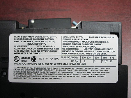
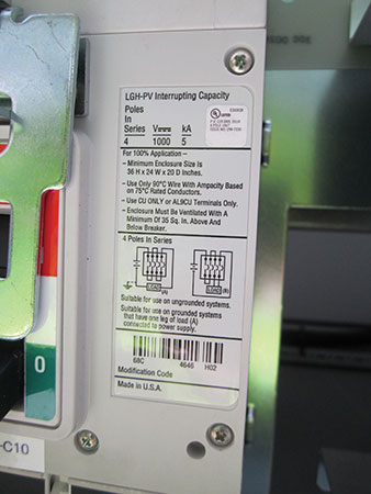
A new rule has been added to Section 2 to provide direction regarding withstand ratings of equipment and equipment with a slash voltage rated such as 125/250V, 120/240V, 208Y/120V, 480Y/277V, or 600 Y/347V, etc. Electrical equipment intended to withstand short circuit current but not intended to interrupt the short circuit current is rated with either a withstand rating or a short circuit current rating (SCCR). New Subrule (1) will provide code users with information required to establish safe installation of the electrical equipment with a SCCR or withstand rating. New Subrule (2) is intended to align requirements in the CE Code with limitations of the applicable product standards and will provide code users with information required to establish proper operation of the electrical equipment without having intimate knowledge of the individual standards. Equipment marked with a slash voltage rating is intended for connection to a system that is solidly grounded.
Existing Table 65 has been expanded to include three new enclosure types. Types 3X, 3RX, and 3SX are enclosures that are provided with corrosion protection.
Rule 2-324 has been revised by replacing the requirement for the 1m clearance distance between arc-producing electrical equipment and a combustible gas relief device or vent, with a reference to CSA Standard B149.1 Natural Gas and Propane Installation Code. A new appendix B note will also be added with the required clearance measurements from the 2010 edition of CSA Standard B149.1
Section 4
In Section 4, a proposal for Rule 4-004 was accepted that aligns the ampacities for single conductor and multi-conductor cables with existing ampacities in Rule 12-2210. Also for Rule 4-004 new subrules, Appendix B notes, configuration drawings, and ampacity tables have been added to clarify ampacities for cable rated between 5 and 46kV. With this change, the titles of Tables 1 through 4 were renamed limiting the maximum voltage to 5kV. The final change to Rule 4-004 is in the underground ampacity tables found in Appendix D; these tables have been now recalculated, and the maximum continuous load conditions from Rule 8-104 were also removed from the tables. At first glance, it will appear that ampacities for underground installation have increased, but keep in mind the maximum continuous load will need to be limited in accordance with Rule 8-104.
Rule 4-006 regarding temperature limitations has been expanded from two to six subrules. The changes include the minimum size for the first 1.2m of conductor to be terminated to equipment based on the allowable ampacity in the corresponding temperature column in Tables 1 through 4 with the relevant correction factors applied. The 90°C default in Subrule (2) has been replaced to align with the termination temperature limitations in the product standards. This change means that for low voltage equipment rated 100 Amps or more marked for use with a conductor larger than No. 1, the default temperature is 75°C, and for low voltage equipment rated 100 Amps or less marked for use with a conductor smaller than No. 1, the default temperature is 60°C.
Cord sets (extension cords) have been added to Rule 4-012 (3) limiting the use of flexible cords and cord sets to the existing requirements in Subrule (3).
Section 6
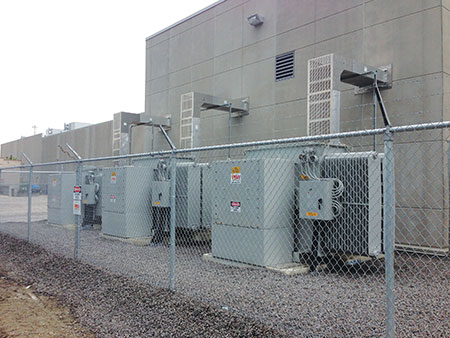
Rule 6-402(2) has been expanded to allow 320 Amp meter mounting devices with a by-pass means to be connected on the line side of the service box. This allowance was added to recognize the increased load from electric vehicles and to recognise similar provisions in the standard for existing meter mounting equipment available and certified for use in Canada.

Section 8
Rule 8-102 covering voltage drop requirements has been expanded from two to four subrules. The main changes are the addition of a new table detailing the maximum length for single dwelling unit branch circuit rated not more that 120V and 20 Amp, and a subrule for industrial establishments where the design will ensure the voltage at the point of utilization is within the tolerance of the connected device.
At the request of the chair of the CE Code, a task group was formed to compare the size of non-residential services and feeders required by Section 8 with actual loads. As a result, Section 8 has seen many changes. First is the addition of definitions “Basic load,” “Calculated load,” and “Demonstrated load” in the special terminology in Rule 8-002. A basic load includes the lighting and receptacles as calculated using Table 14; a calculated load is a load calculated in accordance with Section 8; a demonstrated load is the maximum load recorded over a minimum of 24 months for the same type of facility.
Second is the addition of two subrules to Rule 8-106: one to allow demonstrated loads to be used for feeder and service calculation when performed by a qualified person recognised by the authority having jurisdiction (most likely by a professional engineer or an engineering technologist), and second to allow the acceptable qualified person to apply a demand factor determined by the qualified person.
Third is a wording change to Rule 8-210 for other types of occupancies including the removal of “power loads” and the addition of “motor loads.” And fourth, to combine Rules 8-302 and 8-212 as Rule 8-212 Exit sign, emergency lighting, and show window loads.
Section 10
Section 10 will now recognize material other than copper for uses as a ground conductor in Rules 10-402, 10-406, 10-626, 10-702, 10-802, 10-806, 10-810, 10-816, 10-1000, and 10-1108. In addition, to address possible corrosion issues, a new Subrule (2) has been added to Rule 10-802.
Rule 10-106 has changed by moving the Appendix B note regarding the location and identification of a ground fault detection device to a new Subrule (3) making this a mandatory requirement.
A new Subrule (5) has been added to Rule 10-618 to require a separate bonding conductor to bond fixed equipment when single conductor cables are installed with one end isolated to comply with Rule 4-010.
Rules 10-902 and 10-904 have been amalgamated into a new rule that does not favour a water pipe as a grounding electrode over other acceptable grounding electrodes. This new rule also provides direction that the connection to metallic water pipe in-situ grounding electrodes must be as near as practicable to the point of entrance in the building.
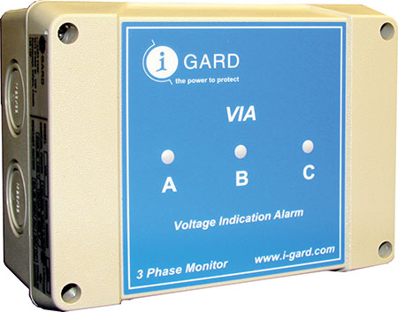
Rule 10-1102 (2) has been modified to require the alarm indicator installed to detect a fault on a system rated 5kV or less with a neutral grounding device is to be identified, and visible or audible to persons monitoring the status of the system. In addition, a new Subrule (5) was added to require the conductor to be continuous between the neutral grounding device and the ground electrode.
Section 12
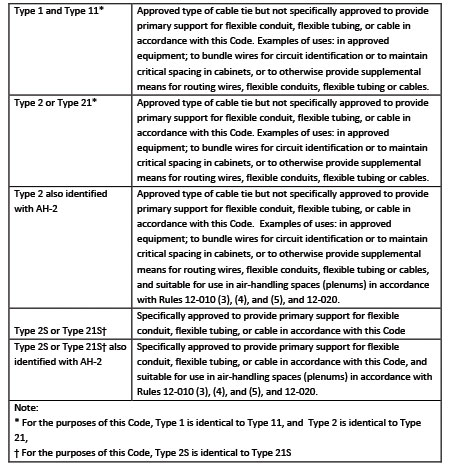
Rules 12-510, 12-706, 12-1010, 12-1308, and 12-1504 have been expanded to allow cable ties of a type specifically approved for the purpose to be used for support of cables and flexible conduit and tubing. The requirements for cable ties have been removed from CSA Standard C22.2 No 18.5-13 and are now found in CSA Standard C22.2 No. 62275-10. To assist code users, a note and table have been added in Appendix B to explain the different types of cable ties and where they can and cannot be used. Starting in June of 2014, each cable tie is required to be marked with the manufacturer’s or responsible vendor’s name, trademark or identifying symbol. In addition, the following markings are required to be provided on labels, packaging, or installation instructions shipped with the cable tie instructions provided with the product:
- a) maximum operating temperature
- b) minimum operating temperature
- c) minimum installation temperature if lower
than 0⁰C (temperature at time of installation advisory only to installer for cold temperature handling)
- d) minimum and maximum bundle diameter
- e) loop tensile strength; and
- f) type designation
The marking indicating the classification “Resistant to ultraviolet light” in accordance with C22.2 No. 62275-10 Clause 6.5.1.2 may alternatively be marked “For use outdoors” or “For use outdoors or indoors” or with an equivalent wording.
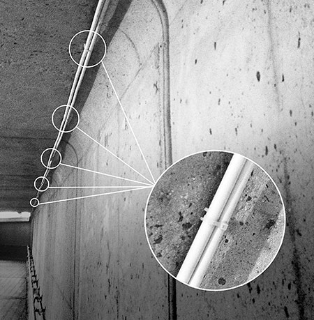
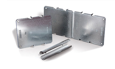
Rule 12-516 for the protection for cable in concealed installations has been revised requiring protector plates used to protect cables installed within 32 mm from the edge of studs, joists, or similar member to be specifically approved for the purpose. This change is to recognise new testing requirements for protector plates and intended to stop the use of unapproved protection like the sides of device boxes being used for this purpose. As an alternative, these rules now recognize a new product called a cylindrical bushing that can be inserted in the hole through the member, provided the cylindrical bushing extends a minimum of 13 mm beyond both sides of the member.
Extra heavy wall reinforced thermosetting resin conduit (RTRC) Type XW has been added to Rules 12-000, 12-1202, and 12-1216. RTRC Type XW conduit is designed to be installed in specified hazardous locations. In addition to the change in Section 12, Rule 18-152 Wiring methods, Class I, Division 2, and Rule 18-252 Wiring methods, Class II, Division 2 have been modified to recognise RTRC Type XW conduit.
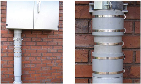
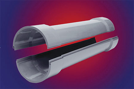
Similar to existing Rule 12-1164, a new Rule 12-1124 has been added to provide direction for the installation and construction of split straight conduit for PVC installations both above and below grade.
The cable tray rule in Section 12 has seen three more changes: first is an exception added to Rule 12-902(2) for cable tray not requiring the separation of different systems; the second is the addition of a new Subrule (7) for Rule 12-2200 that allows a reduced clearance for cable tray through chases, under grating, under process pipes, and other such obstructions; the third addition is a new Subrule (3) added to Rule 12-2208 allowing cable tray with only armoured cable to be installed without additional bonding of the cable tray provided warning notices are posted indicating that only interlocking metal armour cables or continuous metal sheath cables can be installed.
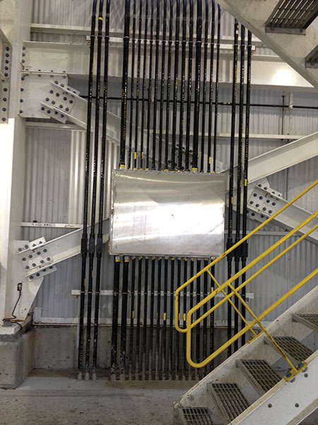
Rule 12-2252 has been changed to recognise Class A and Class B cablebus from the new CSA Standard C22.2 No 273 Cablebus, that defines Class A and Class B cablebus as:
Class A cablebus — cablebus that provides protection from contact with conductors by design and construction of the enclosure.
Class B cablebus — cablebus that does not provide protection from contact with conductors by design and construction of the enclosure.
Note: Cablebus not marked as Class A is considered to be Class B cablebus.
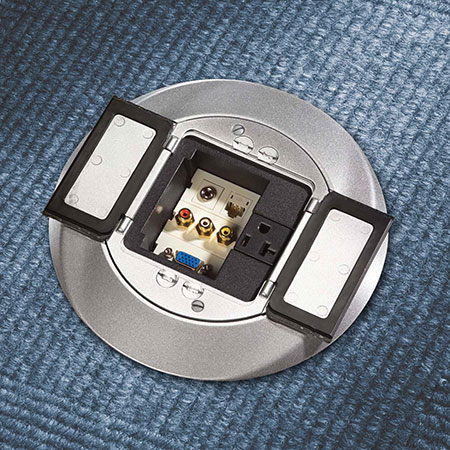
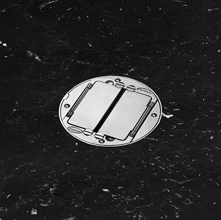
Rule 12-3000 for Outlet boxes, and Rule 12 3002 for Outlet box covers, each have a new subrule to require floor boxes to be installed in accordance with the manufacturer’s installation instructions for the type of floor intended and that the box cover needs to be specifically approved for the type of floor intended. CSA Standards 18.1, Metallic outlet boxes, 18.2, Non-metallic outlet boxes, and 85, Rigid PVC boxes and fittings require that all floor boxes must be provided with installation instructions indicating the type of floor structure for which they are intended to be installed. Floor box covers intended for use only in a floor covered with carpet or wood are marked on the product or smallest unit shipping carton “Not for use with tile covered floors” or the equivalent.
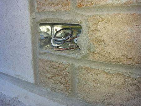
Rule 12-3016 has two new subrules, and the title has been revised to read: Outlet boxes, cabinets, and fittings. Subrule (3) will require outlet boxes intended for installation of a wet location cover plate to be installed so that the box and cover are in intimate contact and will provide a seal to prevent ingress of water into the outlet box. Subrule (4) Flush boxes, cabinets and fittings shall be of a type suitable for the intended location of installation. Will require flush boxes to be of a type approved for the intended location of installation. As an example, a flush box installed in a masonry wall needs be approved for installation in a masonry wall.