It is commonly known that conventional transformers and neutral conductors can become overloaded and hot due to harmonics generated by computer equipment and other non-linear loads. Triplen current harmonics (mainly 3rd and 9th) sum arithmetically in the neutral and circulate in the primary windings of transformers. A simple and effective solution being commonly applied is to use K-rated, or more preferably, harmonic mitigating transformers and to double the ampacity of the neutral conductor. This prevents overheating without introducing negative side effects. Third harmonic blocking filters, on the other hand, reduce neutral current by preventing loads from drawing 3rd harmonic current. They will eliminate neutral conductor and transformer overheating but introduce NEC concerns and the potential for serious power quality issues.
Would you knowingly take medicine that caused side effects more serious than your illness? Of course not, especially if there was another simple cure that had no side effects. Well, this is essentially what is happening when 3rd harmonic blocking filters are used to “cure” overheated neutral conductors. The side effects they introduce are often much more serious concerns than the presence of 3rd harmonic current in the neutral.
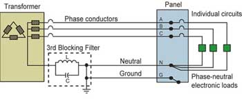
Figure 1. Typical installation of 3rd harmonic blocking filter
The 3rd harmonic blocking filter is a parallel inductive/capactive (L-C) network tuned to the 3rd harmonic (180 Hz for a 60 Hz system) that is connected in series in the neutral conductor of 4-wire systems. The high impedance of the filter at 180 Hz blocks the flow of 3rd harmonic current in the neutral and in the connected equipment. To prevent extremely high levels of neutral-to-ground voltage at the downstream receptacles, the installation requires that the direct neutral-to-ground connection of the transformer secondary be removed and connected to the load side of the harmonic blocking filter (see figure 1).
Although 3rd harmonic current is greatly reduced, it is achieved at the expense of rather severe side effects. Three of the more serious are: (1) the creation of an impedance grounded 4-wire system prohibited by the National Electrical Code (NEC); (2) a significant increase in voltage distortion with its inherent negative effects on the connected equipment; and (3) over- and undervoltages created by neutral reference shift when loads are unbalanced.
Why are harmonics a problem?
By drawing current in pulses rather than in pure sinewaves, non-linear loads (such as computer equipment) generate harmonic currents. These harmonic currents can produce both overheating and power quality problems in a power system if left untreated.
The power distribution equipment which most often overheats due to harmonics are neutral conductors and conventional transformers. Before corrective measures to address harmonics began to be implemented, hot neutrals were being known to cause fires and many transformers failed under what was thought to be relatively light loading.
The power quality problems are primarily due to voltage distortion in the form of flat-topping. Harmonic currents create voltage distortion as they pass through the impedance of a power system. A high impedance system can create very high voltage distortion. When voltage distortion gets severe enough it can cause problems with connected equipment such as premature failure, reduced ride-through capability and other operational problems.
How 3rd harmonic currents overload neutral conductors?

Figure 2. Figure 2 demonstrates how the sinusoidal currents on the phases of a 3-phase, 4-wire system with linear loads sum to return on the neutral conductor.
Figure 2 demonstrates how the sinusoidal currents on the phases of a 3-phase, 4-wire system with linear loads sum to return on the neutral conductor. The 120° phase shift between the sinusoidal load currents causes their balanced portions to cancel. Only the residual unbalanced portion remains. For linear loads, the neutral conductor can be the same size as the phase conductor because the neutral current cannot be larger than the highest phase current. This is not true, however, for non-linear loads.
The narrow pulse currents drawn by non-linear loads will not cancel in the neutral. When one phase is drawing its pulse, the other two phases draw very little current. Hence, little cancellation occurs in the neutral conductor and each pulse of current on a phase becomes a pulse of current on the neutral.
Even if the phase currents of the non-linear loads are perfectly balanced, the neutral current can be as much as Ö3 times the value of the phase current because there are three times as many pulses of current in the neutral than in any one phase. With three times the pulses, the predominant component of the neutral current will be the 3rd harmonic. This is evident in the waveforms of figure 2 since each phase current completes only two cycles in the same time period that the non-linear neutral current completes six cycles (three times the fundamental).
How harmonic currents create voltage distortion?

Figure 3. Relationship between pulsed current and voltage flat-topping
As mentioned earlier, voltage distortion is created as harmonic currents pass through the impedance of a power distribution system. Current at any frequency flowing through an impedance will result in a voltage drop in the system at that frequency. This is a simple application of Ohm’s Law – Vh = Ih x Zh, where:
Vh = voltage at harmonic number h
Ih = current at harmonic number h
Zh = impedance of system to harmonic h
The accumulative effect of the voltage drops at each frequency produces voltage distortion. A common term used to indicate the amount of waveform distortion is total harmonic distortion (THD). THD is expressed as a percentage and for power systems can be applied to both voltage and current. Voltage total harmonic distortion (Vthd) is defined as a root mean square of all the harmonic voltage drops and is expressed as follows:

Voltage distortion then is a function of both the system impedance and the amount of harmonic current in the system. The impedance of long cable runs (especially 4-wire), conventional or K-rated transformers and soft sources (generators and UPS systems) will tend to increase voltage distortion. To prevent high voltage distortion, system impedance should never be increased and the best designs include measures which reduce system impedance such as the use of low zero sequence impedance harmonic mitigating transformers (HMTs).

Figure 4. Figure 4 shows how the DC bus voltage is directly proportional to the peak of the voltage waveform. During each voltage half cycle, the smoothing capacitor is charged by the voltage peak.
Another way to conceptualize harmonic distortion is to consider the current and voltage waveforms themselves. A typical non-linear load, the switch-mode power supply (SMPS) is shown in figure 3. This device draws current only during the peak of the voltage waveform, while charging the smoothing capacitor and supplying the load. As the applied voltage drops during the rest of the cycle, the capacitor discharges to support the load. Since the load only draws current during the peak of the voltage waveform, the instantaneous voltage drop due to the load current will occur only at the peak of the waveform. The resulting voltage distortion is commonly referred to as flat-topping.
The affect of voltage flat-topping on switch-mode power supplies
How voltage flat-topping affects the operation of an SMPS is a somewhat controversial topic. Most equipment manufacturers specify < 5% Vthd in their installation manuals, but many installations today exceed these recommendations. IEEE standard 519, Recommended Practices and Requirements for Harmonic Control in Electrical Power Systems, also lists 5% Vthd as a recommended limit and states, “Computers and allied equipment such as programmable controllers frequently require ac sources that have no more than a 5% harmonic voltage distortion factor, … Higher levels of harmonics result in erratic, sometimes subtle, malfunctions of the equipment that can, in some cases, have serious consequences.”

Figure 5. How voltage flat-topping reduces ride-through capability
Often the equipment appears to operate normally but the long-term effect of exposure to a severely distorted or flattened voltage waveform is rarely considered. A drop in peak voltage will directly reduce the DC bus voltage within an SMPS. Figure 4 shows how the DC bus voltage is directly proportional to the peak of the voltage waveform. During each voltage half cycle, the smoothing capacitor is charged by the voltage peak. It then discharges to support the DC voltage as the supply voltage drops to zero and back up to its peak. The result is a DC voltage with a slight DC ripple.
When the SMPS is supplied by a sinusoidal waveform of nominal voltage, its DC bus voltage will be normal. When the voltage peak is flattened, however, the DC bus voltage will be lowered proportionately. With a reduced DC bus voltage, the SMPS must draw more current to supply the power demands of the load (P = V x I). This increased current will increase the internal I2R losses and the heat these losses produce. Components within the SMPS will then run hotter and can fail prematurely.
Another negative affect of a lower peak supply voltage is reduced ride-through capability. With a full peak voltage, the smoothing capacitor in the SMPS often has enough charged energy to support the load during a brief power interruption. This is why a personal computer is often unaffected when the lights in the office area flicker during a thunderstorm or other inclement weather condition.
With a flattened voltage waveform, however, the smoothing capacitor will not get fully charged. With less stored energy, this capacitor might no longer be capable of supporting a load during the full duration of a power interruption and the equipment could shut down. Since the energy in a capacitor is proportional to the square of the applied voltage, a 10 percent drop in peak voltage can result in a >35% drop in ride-through capability (see figure 5).
The problem of voltage flat-topping becomes even more severe when a system’s impedance to the flow of harmonic currents is increased as is the case with the 3rd harmonic blocking filter. Manufacturers of these filters readily admit that a reduction in ride-through capability is one consequence of their filters’ use.
How the use of 3rd harmonic blocking filters raises NEC concerns?
One of the more significant consequences of applying a 3rd harmonic blocking filter is that its installation raises questions with respect toNEC2002 compliance. Manufacturer’s instructions require that the filter be installed in series between the neutral point of the transformer and its ground connection (see figure 1). Leaving the ground connected directly to the neutral point of the transformer would result in neutral-to-ground voltages (particularly at the 3rd harmonic) that would be unacceptably high due to the voltage drop across the filter (as high as 30 to 40 Vrms at heavier loading).
NECparagraph 250.20(B) states that: “Alternating-current systems of 50 volts to 1000 volts that supply premises wiring and premises wiring systems shall be grounded under any of the following conditions: (1) Where the system can be grounded so that the maximum voltage to ground on the ungrounded conductors does not exceed 150 volts; (2) Where the system is 3-phase, 4-wire, wye-connected in which the neutral is used as a circuit conductor …”

Figure 6. Figure 6 shows voltage distortion measured at a site in which a 3rd harmonic blocking filter was installed and loaded to about 50 percent.
Standard grounding practice requires that the neutral of a separately derived source, such as the wye secondary of a transformer, be connected directly to ground without introducing any intentional impedance in the grounding path. NEC 250.2 defines “Effective Ground-Fault Current Path as an intentionally constructed, permanent, low-impedance electrically conductive path designed to carry current under ground-fault conditions from point of ground fault on a wiring system to the electrical supply source” [italics added]. Insertion of the 3rd harmonic blocking filter violates this requirement by adding impedance between the neutral point and the ground connection. A low impedance fault-current path is essential for ensuring that enough current flows through the circuit breaker to clear a fault.
NEC 250.30(A)(2)(a) states that “a grounding electrode conductor for a single separately derived system…shall be used to connect the grounded conductor of the derived system to the grounding electrode….” In addition, “the grounding electrode conductor shall be installed in one continuous length without a splice or joint.…” [italics added. See NEC 250.64(C)]. If a simple splice connection isn’t even allowed, then certainly the L-C circuit of the 3rd harmonic blocking filter should not be allowed either.
The only reference in the NEC that allows for the introduction of impedance between the neutral and the grounding electrode is found in Section 250.36, High-Impedance Grounded Neutral Systems. However, these systems are permitted only at 480 V and higher and only if they do not serve line-to-neutral loads. They also require the use of ground-fault detectors. None of these requirements is met in the normal application of the 3rd harmonic blocking filter where the loads are primarily 120 V, phase-to-neutral connected computer equipment.

Figure 7. Figure 7 shows how the neutral point of the secondary wye transformer connection will shift as neutral current flows through the impedance of the 3rd harmonic blocking filter.
There are many reasons for not allowing impedance grounded systems but probably the most crucial is the increased potential for arcing faults and the fire hazard these would introduce. Under a fault condition, an impedance grounded system could limit the fault current such that it prevents circuit breakers from clearing the fault. If not cleared, the fault could easily begin to arc, overheat, and produce a fire.
Voltage distortion increase caused by 3rd harmonic blocking filters
Because of its high impedance to 3rd harmonic current, the 3rd harmonic blocking filter will produce much higher voltage distortion at this harmonic. The result is a severely flat-topped voltage waveform. Figure 6 shows voltage distortion measured at a site in which a 3rd harmonic blocking filter was installed and loaded to about 50 percent. The severity of the voltage flat-topping is quite evident with total harmonic voltage distortion exceeding 30 percent. Heavier loading would distort the voltage even further.
At 30 percent, the voltage distortion was six times the maximum limit of 5 percent recommended by IEEE standard 519. In addition, the crest factor of 1.19 was 19 percent below the normal sinusoidal crest factor of 1.414. As discussed earlier, this level of distortion can affect connected equipment, by way of:
1. significantly reducing the ride-through capability of switch-mode power supplies;
2. decreasing connected equipment reliability by lowering the SMPS DC bus voltage which increases current demand, I2R losses, and component operating temperatures;
3. causing single-phase UPS systems to switch to battery backup due to distorted supply voltage;
4. producing light flickering due to momentary current bursts of laser printers or other single-phase intermittent loads;
5. causing overheating in rotating equipment, such as induction motors.
At first, when loading is light, problems may not be obvious. However, as load increases, voltage distortion and flat-topping will also increase until problems are very likely to arise.
Neutral reference shift due to unbalanced loading
When impedance is inserted in the return neutral path of a 4-wire system, the voltage drop across this impedance can result in a shift of the neutral reference point. This is particularly evident when the loads on the various phases are unbalanced.
Figure 7 shows how the neutral point of the secondary wye transformer connection will shift as neutral current flows through the impedance of the 3rd harmonic blocking filter. The amount of shift is dependent upon the relative impedance of the filter and the unbalance between the loads on the three phases. This shift will result in a change in the phase-to-neutral voltages. One phase may see a drop in the phase-to-neutral voltage while another phase sees an increase. Since balanced loading can never be guaranteed, the use of 3rd harmonic blocking filters will always have the potential of introducing very troublesome over- and/or undervoltage conditions at the connected equipment.
Conclusion
Since harmonic induced overheated neutrals and transformers can be suitably addressed by doubling neutral conductors and using HMT or K-rated transformers, it seems puzzling that a solution that requires the use of questionable grounding practices and that can introduce serious power quality side effects would justify any consideration for use. It can only be concluded that these decisions are being made without full consideration of minimum safety code requirements and understanding of the consequences.
Although harmonics are certainly a performance issue which requires our attention, treatment of one problem must not be done at the expense of other, more serious problems. In that regard, it is the author’s opinion that the use of 3rd harmonic blocking filters should be avoided under any circumstances.